Table of Contents
Advertisement
Quick Links
Advertisement
Table of Contents

Related Manuals for FOR-A Multi Viewer MV-40F(A)


Summary of Contents for FOR-A Multi Viewer MV-40F(A)
- Page 1 OPERATION MANUAL MV-40F(A) Multi Viewer Edition S/N 9075301 - Higher...
- Page 3 Precautions Important Safety Warnings [Power] Operate unit only on the specified supply voltage. Caution Disconnect power cord by connector only. Do not pull on cable portion. Do not place or drop heavy or sharp-edged objects on power cord. A damaged cord can cause fire or electrical shock hazards.
-
Page 4: Backup Battery
[Circuitry Access] Do not remove covers, panels, casing, or access circuitry with power applied to the unit! Turn power off and disconnect power cord prior to removal. Internal servicing / adjustment of unit should only be performed by qualified personnel. Do not touch any parts / circuitry with a high heat factor. - Page 5 Upon Receipt Unpacking The MV-40F is fully inspected and adjusted prior to shipment and can be operated immediately upon completing all required connections and operational settings. Check your received items against the packing list below. ITEM REMARKS MV-40F NTSC or PAL user selectable AC Cable For unit power supply Operation Manual...
-
Page 7: Table Of Contents
TABLE OF CONTENTS 1. Prior to Starting ....................... 1 1-1. Welcome ......................1 1-2. About the MV-40F..................... 1 1-3. About This Manual.................... 2 2. Panel Descriptions ....................3 2-1. Front Panel....................... 3 2-2. Rear Panel ....................... 4 3. Connection Example....................5 3-1. - Page 8 4-5-13. Unit Reset ................... 25 4-6. External Alarm Function.................. 26 4-7. Video Loss Alarm .................... 29 4-8. Alarm Reset ....................32 4-9. Alarm Quick Reference Chart ................. 33 4-10. Video Loss Quick Reference Chart............... 34 5. Main Menu......................36 5-1. Accessing and Changing Menus..............38 5-2.
- Page 9 7-10. Split 2 or Split 3 Screen Request and Reply..........59 8. Specifications & Dimensions................. 61 8-1. Specifications ....................61 8-2. External Dimensions ..................62 8-2-1. Single Unit Rack Mounting ..............62 8-2-1. Single Unit Rack Mounting ..............63 8-2-2. Dual Unit Rack Mounting..............63...
-
Page 11: Prior To Starting
1. Prior to Starting 1-1. Welcome Congratulations! By purchasing the MV-40F you have entered the world of FOR.A and our many innovative products. Thank you for your patronage and we hope you will turn to FOR.A products again and again to satisfy your video and audio production needs. FOR.A provides a wide range of products, from basic support units to complex system controllers, which have been increasingly joined by products for computer video based systems. -
Page 12: About This Manual
1-3. About This Manual This manual is intended to help the user easily operate the MV-40F and make full use of its functions during operations. Before connecting or operating your unit, read this operation manual thoroughly to ensure you understand the product. After reading, it is important to keep this manual in a safe place and available for future reference. -
Page 13: Panel Descriptions
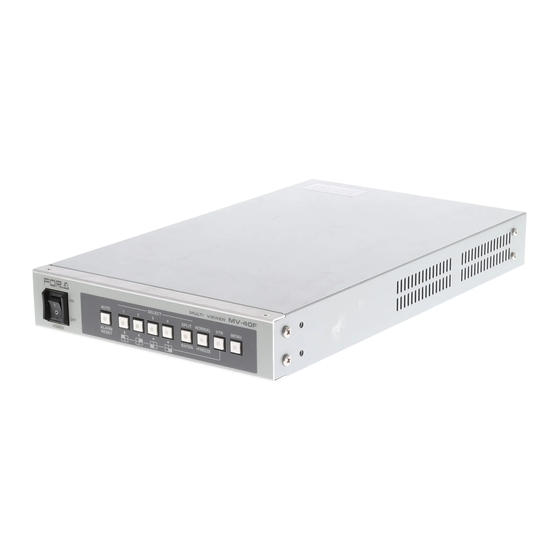
2. Panel Descriptions 2-1. Front Panel ⑥ ③ ⑤ MV-40F MULTI VIEWER SELECT AUTO SPLIT NORMAL MENU ALARM ENTER *FREEZE RESET POWER ② ① ④ ⑤ ⑦ ⑧ ⑨ ① Power switch and indicator Used to turn unit power ON / OFF. ②... -
Page 14: Rear Panel
⑨ MENU Used to access menu mode for setting unit parameters such as title, position, character type, etc. Switch indicator lights when MENU mode selected. See sec. ‘5. Main Menu’ for details. 2-2. Rear Panel ③ ⑦ ① SER.No PB IN REC OUT Ω... -
Page 15: Connection Example
3. Connection Example 3-1. Computer Control Basic RS-232C interface connection example is given in the figure below. Monitor SER.No PB IN REC OUT Ω REMOTE/ALARM VIDEO IN (75 AUTO TERM) MONITOR To other system equipment (see note below) NOTE See sec. ‘3-3. Remote / Alarm Connector’ following for REMOTE/ALARM connector and alarm circuit information. -
Page 16: External Alarm Input
3-2. External Alarm Input Basic alarm connection example is given in the figure below. Monitor SER.No PB IN REC OUT Ω VIDEO IN (75 AUTO TERM) MONITOR REMOTE/ALARM Alarm signal input To other (see note below) system equipment NOTE See sec. ‘3-3. Remote / Alarm Connector’ following for REMOTE/ALARM connector and alarm circuit information. -
Page 17: Remote / Alarm Connector
3-3. Remote / Alarm Connector Connector appearance and pin assignments are as below. REMOTE/ALARM 25-pin D-sub (female) Pin Assignment Table PIN No SIGNAL PIN No SIGNAL REMOTE AUTO/RST ALARM MAKE REMOTE CH1 ALARM COM REMOTE CH2 ALARM BREAK REMOTE CH3 NOT USED REMOTE CH4 RS-232C TXD... -
Page 18: Remote Control
3-4. Remote Control Remote control functions enable switch operations from a remote box are as shown below. Remote Control Functions Pin No. SIGNAL Function REMOTE AUTO/RST Same as front panel AUTO/ALARM RESET switch REMOTE CH1 Same as front panel SELECT1 switch REMOTE CH2 Same as front panel SELECT2 switch REMOTE CH3... -
Page 19: Remote Control Circuit Diagram
3-4-2. Remote Control Circuit Diagram Remote control circuit is shown as below with external device examples. See sec. ‘3-3. Remote / Alarm Connector’ for details on pin assignments. NOTE Remote operation is initiated by TTL level negative logic pulse more than 100ms pulse width. A delay of more than 100ms between signal inputs is required for proper remote control operation. -
Page 20: Alarm Circuit
3-5. Alarm Circuit Alarm input and output circuits with external input device examples are as shown below. See sec. ‘3-3. Remote / Alarm Connector’ for details on pin assignments. NOTE larm initiated by TTL negative logic level signal if menu alarm set to LEVEL. - Page 21 Alarm output circuit with external display device example MAKE (Pin 14) BREAK (Pin 15) Max load 24VDC 100mA Com (Pin 15) MV-40F side External device side NOTE Maximum load: 24VDC 100mA or lower Alarm output signals Normal condition BREAK and COM shorted, MAKE is open. Alarm condition MAKE and COM shorted, BREAK open.
-
Page 22: Operation
4. Operation 4-1. Prior to Operation Before operating MV-40F, verify the following points: Verify all cabling connections are securely made. Verify unit is properly grounded for use in your system. 4-2. Installation Precautions When mounting multiple units be sure not to locate any other electrical unit closer than the dimensions shown below. -
Page 23: Memory Backup
5-years when unit is used at normal room temperature (around 25 degrees). When the backup battery needs replacement, 'BACKUP ERROR TIME RESET' will be monitor displayed. Contact your FOR-A supplier for battery replacement procedures. 4-4. Power ON When power is turned on, the last screen setup is monitor displayed. -
Page 24: Front Panel Controls
4-5. Front Panel Controls The MV-40F front panel controls can be used to select and change operational settings, levels, parameters and views as well as to make other settings in the operational menu. 4-5-1. NTSC / PAL Select You can set your MV-40F to either NTSC or PAL format as shown below. SELECT 1 - 4 MV-40F MULTI VIEWER... -
Page 25: Full Screen Mode
4-5-2. Full Screen Mode SELECT switches 1 - 4 are used to full screen monitor display one screen image at a time. For example, if SELECT switch 3 is pushed and video is present at input 3, channel 3 video will be monitor displayed. -
Page 26: Full Screen Auto
4-5-3. Full Screen Auto Full screen channels can be automatically switched between to sequentially view all inputs by pushing AUTO switch when operating in full screen mode. Channels without a video input connected will be auto skipped. Dwell time between channel switching can be user set. See AUTO SEQ TIME parameter in sec. -
Page 27: Display Mode Quick Reference Chart
4-5-5. Display Mode Quick Reference Chart The following quick reference chart is designed to help the operator thoroughly understand and use the Display functions of the MV-40F. POWER ON Monitor Display Types Push MENU Push MENU select DISPLAY then select DISPLAY TYPE and use left and right switches to select one of the (Factory Default) above Monitor Display Types. -
Page 28: Selecting Split Screen Display
4-5-6. Selecting Split Screen Display The MV-40F display split screen mode is set in the Display menu. The procedure to do this is following. ENTER MV-40F MULTI VIEWER SELECT AUTO SPLIT NORMAL MENU ALARM ENTER *FREEZE RESET POWER MENU Push MENU switch, use up ↑ and down ↓ switch to move cursor to DISPLAY and press ①... -
Page 29: 4-5-7.Setting Screen Position
4-5-7.Setting Screen Position Settings can be made to adjust where P-in-P screen(s) are positioned or to pan / tilt the picture in split 2 or split 3 screen mode. ENTER MV-40F MULTI VIEWER SELECT AUTO SPLIT NORMAL MENU ALARM ENTER *FREEZE RESET POWER MENU... -
Page 30: Setting Channel Assign
④ Push ENTER switch to select a different half size screen (title flashing) in H2 or V2 mode to change the display position. ⑤ Push MENU switch to finish making split 2 or split 3 screen display position changes and to return to DISPLAY screen. ⑥... -
Page 31: Freeze Select
4-5-9. Freeze Select Freeze screen operation is used to pause the image(s) on the desired channel(s). NOTE If a frozen channel loses video input, Freeze is automatically interrupted. To freeze a video display in full screen mode: ① Push SELECT 1 – 4 switch to select which channel you wish to freeze. ②... - Page 32 To Freeze All displayed Video in split and P-in-P screen mode: ① Push FREEZE switch to lit to select freeze operation. ② Push SPLIT switch to freeze all displayed channels. ③ All channels will freeze and FREEZE will be monitor displayed at all frozen channels. ④...
-
Page 33: Freeze Mode Quick Reference Chart
4-5-10. Freeze Mode Quick Reference Chart The following quick reference chart is designed to help the operator thoroughly understand the FREEZE functions of the MV-40F. Normal Status Normal Display FREEZE switch unlit Push FREEZE Push FREEZE switch to Push FREEZE switch switch to unlit unlit FREEZE switch lit... -
Page 34: Vtr Record / Playback
4-5-11. VTR Record / Playback Previously recorded video material can be played back and viewed when material is input to the VTR PB IN terminal. VTR mode is selected and playback video is output to monitor via MONITOR OUT connector. While in VTR playback mode, played back images can be twice zoomed. -
Page 35: Zoom Display
4-5-12. Zoom Display While in VTR playback mode, the image being played back can be twice zoomed as below. To Zoom Playback Video: ① Push VTR switch to lit, ② Push SELECT 1 – 4 switch one time to twice zoom in on that image channel. ③... -
Page 36: External Alarm Function
4-6. External Alarm Function An external alarm device can be used to input an alarm signal to the MV-40F rear panel REMOTE/ALARM connector. Input signal will initiate alarm operation at MV-40F. NOTES If ALARM is set to OFF in the setup menu, alarm input will be ignored and alarm operation will not occur. - Page 37 ③ After alarm duration ends, alarm signal output at REMOTE/ALARM connector will go OFF, buzzer stops and unit automatically returns to previous operation. Alarm ends Alarm begins ALARM Channel 1 Return to Displayed channel 1 ALARM If alarm occurs in currently displayed channel while in P in P, split 2 or 3 mode; ①...
- Page 38 If alarm occurs while in Quad mode; ① ‘ALARM’ flashes on display of all channels in alarm if MARK superimpose set to ON. (See sec. ‘5-5. Display’ for MARK ON/OFF). ALARM buzzer sounds for alarm duration if BUZZER set to ON. (See sec. ‘5-3. Alarm / Video Loss’ to set BUZZER ON/OFF.) ②...
-
Page 39: Video Loss Alarm
4-7. Video Loss Alarm The MV-40F can be set to go to video loss alarm operation whenever channel input is suddenly lost. NOTE If LOSS is set to OFF in the setup menu, video loss will be ignored and video loss alarm operation will not occur. Refer to sec. - Page 40 If video loss occurs in channel not currently displayed, while in full screen mode; ① Full screen display changes to Quad display. Lost signal channel will appear black and display flashing 'LOSS' if MARK superimpose set to ON. (See sec. ‘5-5. Display’ for MARK ON/OFF.) Buzzer sounds if BUZZER set to ON.
- Page 41 If video loss occurs in channel not currently displayed while in P in P, 2 or 3 split mode; ① Current display changes to Quad display. All lost signal channels will appear black and display flashing 'LOSS' if MARK superimpose set to ON. (See sec. ‘5-5. Display’ for MARK ON/OFF.) Buzzer sounds for alarm duration if BUZZER is set to ON.
-
Page 42: Alarm Reset
4-8. Alarm Reset It is possible to manually stop alarm operation or to reset LOSS RST TIME timer to zero by pushing the front panel ALARM RESET switch. MV-40F MULTI VIEWER SELECT AUTO SPLIT NORMAL MENU ALARM ENTER *FREEZE RESET POWER ALARM RESET NOTE... -
Page 43: Alarm Quick Reference Chart
4-9. Alarm Quick Reference Chart Alarm operations are summarized for your reference. Note that ALARM RESET switch can be used only when ALARM MODE is set to TRIG. If alarm occurs in only one channel while in full screen mode; Alarm begins Alarm ends Alarm channel... -
Page 44: Video Loss Quick Reference Chart
If alarm occurs in channel not currently displayed, while in P in P, split 2 or 3 mode; Alarm ends Alarm begins ALARM ALARM ALARM RESET switch pushed If alarm occurs while in Quad mode; Alarm ends Alarm begins Return to Display Display ALARM... - Page 45 If video loss occurs in currently displayed channel while in P in P, split 2 or 3 mode; Video lost LOSS RST Video Restored time expired Return to Channel 1 channel 1 displayed LOSS LOSS ALARM RESET switch pushed If video loss occurs in channel not currently displayed while in P in P, split 2 or 3 mode; LOSS RST time expired Video lost...
-
Page 46: Main Menu
5. Main Menu Menus can be accessed and settings made as below. To access main menu: Settings that can be made in the main menu are as follows; Push MENU switch to lit indication. The main menu will be monitor displayed. Scroll cursor up or down using up ↑... - Page 47 Where Item Information Reference Date and time setting Automatic switching timer setting ① TIME SETUP Automatic screen switching timer setting Sec. ‘5-2. Time Setup’ Alarm auto-reset timer setting Video loss auto-reset timer setting Alarm ON/OFF Video Loss ON/OFF Alarm mode Level/Trigger ②...
-
Page 48: Accessing And Changing Menus
5-1. Accessing and Changing Menus The MAIN Menu and related Sub Menus are used to make all general operational settings and to display related settings. Changing Menu Parameter Settings To select and modify settings in this type of menu use the front panel controls. Standard switch use is as listed in the following chart. -
Page 49: Time Setup
5-2. Time Setup Settings that can be made in the Time Setup screen are as follows. From MAIN MENU use up ↑ and down ↓ switch to move cursor to TIME SETUP and press ENTER switch. The display below should appear. TIME SETUP ①... - Page 50 Adjusting Date and Time Use up ↑ and down ↓ switch to move cursor to date and time display ② and push ENTER switch. Date and time display should appear as below with year numbers flashing. (Hatched area shows flashing figures below.) Date format example shown below is TIME DISPLAY default 2 (NTSC).
-
Page 51: Alarm / Video Loss
5-3. Alarm / Video Loss Settings that can be made in the ALARM/VIDEO LOSS screen are as follows. From MAIN MENU, use up ↑ and down ↓ switch to move cursor to ALARM/VIDEO LOSS and press ENTER switch. The display below should appear. ALARM/VIDEO LOSS ①... -
Page 52: Title/Position
5-4. Title/Position Settings that can be made in the Title/Position screen are as follows. From MAIN MENU, use up ↑ and down ↓ switch to move cursor to TITLE/POSITION and press ENTER switch. The display below should appear. TITLE/POSITION ① TITLE SET ②... -
Page 53: Title Position
Inputting characters Use left ← and right → switch to move cursor forward and backward in a line. ① Use up ↑ and down ↓ switch to change character selection. Character selection ② sequence is shown on the table below. ③... -
Page 54: Timer Position
5-4-3. Timer Position From TITLE/POSITION menu, use up ↑ and down ↓ switch to move cursor to TIMER POSITION and push ENTER switch. The display below should appear. 2002-09-11 09:32:10 TIMER POSITION CAMERA1 CAMERA2 CAMERA3 CAMERA4 Press either up ↑ or down ↓ switch to move Timer Position to either the top or the bottom of the screen. -
Page 55: Display
5-5. Display From MAIN MENU, use up ↑ and down ↓ switch to move cursor to DISPLAY and push ENTER switch. The display below should appear. Push MENU switch to return to main menu. DISPLAY ① DISPLAY TYPE QUAD ② REC OUT QUAD TITLE... -
Page 56: Display Set
Item Description Sets TITLE display ON / OFF. ③ TITLE Use cursor ← → switches to select. Sets ALARM, LOSS and FREEZE display ON / OFF. ④ MARK Use cursor ← → switches to select. Sets date display ON / OFF. ⑤... -
Page 57: P-In-P Mode
5-6-1. P-in-P mode When in P-in-P mode, you can change the display positions of P-in-P inset screen when the title is flashing. Factory default P-in-P inset screen positions are as shown below. P-in-P1 P-in-P2 P-in-P3 The following table shows how to adjust P-in-P inset screen position. Control Result ↑... -
Page 58: Split 2 Or 3 Mode
5-6-2. Split 2 or 3 Mode 2002-10-10 10:10:10 DISPLAY SET CAMERA1 CAMERA2 When in V2, H2, V3 or H3 mode, only half sized screen view can be adjusted by tilt up/down or pan left/right. Also when in V2 or H2 mode, only the title flashing screen view can be adjusted. -
Page 59: Channel Assign
5-6-3. Channel Assign While in DISPLAY SET menu, push FREEZE switch to go to CH ASSIGN menu shown as below. 2002-10-10 10:10:10 CH ASSIGN CAMERA2 CAMERA3 CAMERA4 CAMERA1 Factory default P-in-P3 channel assignment is shown above for example. Title flashing screen channel can only be assigned (hatched in the figure above). - Page 60 When CH2 is assigned to full Assigning CH2 to full screen. screen from P–in-P inset screen, the previous full screen channel is displayed in the P–in-P inset screen where CH2 was previously displayed. Factory default channel assignments are shown below. Full screen PinP1 PinP2...
-
Page 61: Other
5-7. Other Settings can be made here allows the user to reset all settings (except Date and Time) to factory defaults. From Main Menu use up ↑ and down ↓ switch to move cursor to OTHER and press ENTER switch. The display below should appear. OTHER MEM CLR Push MENU switch to return to MAIN MENU. -
Page 62: Rs-232C Remote Control
6. RS-232C Remote Control Personal computer can be connected for RS-232C control to REMOTE/ALARM connector of MV-40F. For REMOTE/ALARM connector pin assignment, see sec. ‘3-3. Remote / Alarm Connector’. 6-1. Connection Connection cable between personal computer and MV-40F is specified below. Personal Computer MV-40F side Pin No. -
Page 63: Computer Transmit
6-4. Computer Transmit Personal computer transmits control commands using the format as shown below. It starts with STX code (value 02H), command contents in ASCII code, and ends with ETX code (value 03H). Variable data See sec ‘7. RS-232C Control Commands’ following for details. (Command) 6-5. -
Page 64: Rs-232C Control Commands
7. RS-232C Control Commands All command contents are transmitted in ASCII code. Note that commands cannot be processed while either in menu operation or during alarm / video loss alarm operation. If command is received while in menu operation or during alarm / video loss alarm operation, MV-40F sends NAK (15H) reply. -
Page 65: Freeze Commands
7-2. Freeze Commands Function Command All channels Freeze ON All channels Freeze OFF CH1 Freeze ON FMO1 CH2 Freeze ON FMO2 CH3 Freeze ON FMO3 CH4 Freeze ON FMO4 CH1 Freeze OFF FMF1 CH2 Freeze OFF FMF2 CH3 Freeze OFF FMF3 CH4 Freeze OFF FMF4... -
Page 66: Alarm Functions
7-4. Alarm Functions Alarm function commands are listed in the table below. Function Command Buzzer OFF Buzzer ON Alarm Reset NOTE When ALARM MODE is set to 'LEVEL' by menu setting and Alarm Reset command ‘AR’ is received, MV-40F replies NAK (15H). -
Page 67: Split Screen 2 And 3 Positioning
7-6. Split Screen 2 and 3 Positioning Half size screen view of split 2 (V2 or H2) and split 3 (V3 or H3) can be set using commands listed below. Function Command Default view setting NTSC V2 view setting DM1xxxx 4646 4646 H2 view setting... -
Page 68: Display Status Request And Reply
7-7. Display Status Request and Reply Display status request command is ?G and replies are listed in the table below. MV-40F replies with one of the messages below. Reply Message Reply Meaning Full screen CH1 Full screen CH2 Full screen CH3 Full screen CH4 Full screen, automatic channel switching 4 Split (Quad) -
Page 69: P-In-P Inset Screen Position Request And Reply
7-9. P-in-P Inset Screen Position Request and Reply There are 3 commands used for P-in-P inset screen position request depending on which display type is currently being used. Commands and their replies are listed in the table below. Request Command Function Reply Message PinP1 inset screen position request... - Page 70 D2yyyy **¤¤ **: Upper side half screen view setting ¤¤: Lower side half screen view setting T1xx Split V3 view has only one half size screen, just one pan setting. T2yy Split H3 view has only one half size screen, just one tilt setting. NOTE Command and reply are all in ASCII code notation.
-
Page 71: Specifications & Dimensions
8. Specifications & Dimensions 8-1. Specifications Standard 525/60 (NTSC) or 625/50 (PAL) 1.0Vp-p color or B/W (59.94Hz), 75Ω or loopthru auto terminated, 4 ea., Video Inputs VTR generated 1.0Vp-p, 75Ω, 1 ea., BNC VTR Input 1.0Vp-p±0.1V, 1 ea., BNC, Full screen view or split screen view Monitor Output VTR OUT 1.0Vp-p±0.1V,1 ea., Quad or the same screen view with monitor. -
Page 72: External Dimensions
8-2. External Dimensions (All dimensions in mm) MV-40F MU LTI VIEWER SELECT AUTO SPLIT NORM AL MENU ALA RM ENTER *FREEZE RESET POWER ø12.7... -
Page 73: Single Unit Rack Mounting
8-2-1. Single Unit Rack Mounting (All dimensions in mm) MV-40F MULTI V IEWER SELECT SPLIT NORMAL MENU AUTO ALARM ENTER *FREEZE RESET POWER 2x2-6.4x12 8-2-2. Dual Unit Rack Mounting (All dimensions in mm) MV-40F MV-40F MULTI VIEWER MULTI VIEWER SELECT SELECT SPLIT NORMAL... - Page 75 Warning This equipment has been tested and found to comply with the limits for a Class A digital device, pursuant to Part 15 of FCC Rules. These limits are designed to provide reasonable protection against harmful interference when the equipment is operated in a commercial environment. This equipment generates, uses, and can radiate radio frequency energy and, if not installed and used in accordance with the instruction manual, may cause harmful interference to radio communications.
- Page 76 Two Executive Drive, Suite 670, Fort Lee Executive Park, Fort Lee NJ 07024, USA Phone: +1 (201) 944-1120 Fax : +1 (201) 944-1132 FOR-A America Distribution & Service Center 2400 N.E. Waldo Road, Gainesville, FL 32609, USA Phone: +1 352-371-1505 Fax: +1 352-378-5320...
Need help?
Do you have a question about the Multi Viewer MV-40F(A) and is the answer not in the manual?
Questions and answers