Table of Contents
Advertisement
Quick Links
Advertisement
Table of Contents

Related Manuals for TYAN TA77-B7061


Summary of Contents for TYAN TA77-B7061
- Page 1 TA77-B7061 Service Engineer’s Manual http://www.tyan.com...
- Page 2 Corporation and has been reviewed for accuracy and reliability prior to printing. MiTAC assumes no liability whatsoever, and disclaims any ® express or implied warranty, relating to sale and/or use of TYAN products including liability or warranties relating to fitness for a particular purpose or merchantability.
- Page 3 There will be danger of explosion if battery is incorrectly replaced. Replace only with the same or equivalent type recommended by manufacturer. Dispose of used battery according to manufacturer instructions and in accordance with your local regulations. http://www.tyan.com...
-
Page 4: About This Manual
This manual consists of the following parts: Chapter 1: Overview Provides an introduction to the TYAN TA77-B7061 barebones, standard parts list, describes the external components, gives a table of key components, and provides block diagram of the system. -
Page 5: Safety And Compliance Information
Safety and Compliance Information Before installing and using TYAN TA77-B7061, take note of the following precautions: ·Read all instructions carefully. ·Do not place the unit on an unstable surface, cart, or stand. ·Do not block the slots and opening on the unit, which are provided for ventilation. -
Page 6: Safety Information
To reduce the risk of bodily injury, electric shock, fire and damage to the equipment, observe all precautions included in this guide. You must become familiar with the safety information in this guide before you install, operate, or service TYAN products. Symbols on Equipment Warning. This symbol indicates the presence of hazardous energy circuits or electric shock hazards. - Page 7 · Make sure racks are coupled together if it is a multiple-rack installation. · Make sure the rack is level and stable before installing an appliance in the rack. · Make sure the leveling jacks are extended to the floor. http://www.tyan.com...
- Page 8 · Plug the power cord into a grounded (earthed) electrical outlet that is easily accessible at all times. · In all European electrical environments, you must ground the Green/Yellow tab on the power cord. If you do not ground the http://www.tyan.com...
- Page 9 TYAN, your authorized TYAN partner, or their agents. Equipment Modifications · Do not make mechanical modifications to the system. TYAN is not responsible for the regulatory compliance of TYAN equipment that has been modified.
- Page 10 – Liquid has been spilled on the product or an object has fallen into the product. – The product has been exposed to rain or water. – The product has been dropped or damaged. – The product does not operate normally when you follow the operating instructions. http://www.tyan.com...
-
Page 11: Table Of Contents
Table of Contents Chapter 1: Overview ............... 14 About the TYAN TA77-B7061 ..........14 Product Model................. 14 Features.................. 15 Standard Parts List ..............18 1.4.1 Box Contents ..............18 1.4.2 Accessories ..............20 About the Product ..............21 1.5.1 System Front View ............21 1.5.2... - Page 12 Event Logs................152 Chapter 7: Diagnostics ..............153 Flash Utility ................153 AMIBIOS Post Code (Aptio) ..........154 Appendix I: Fan and Temp Sensors..........163 Appendix II: Cable Connection Tables ........167 Appendix III: FRU Parts Table ............. 169 http://www.tyan.com...
- Page 13 Appendix IV: Technical Support ..........171 http://www.tyan.com...
-
Page 14: Chapter 1: Overview
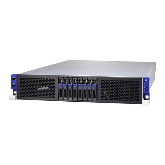
The TA77-B7061 not only empowers your company in nowadays IT demand but also offers a smooth path for future application usage. ® TYAN is also proud to deliver the TA77-B7061 in a version that can support up ® to eight 2.5” hot-swap hard drives. The TA77-B7061 uses TYAN ’s latest chassis featuring a robust structure and a solid mechanical enclosure. -
Page 15: Features
Features TYAN TA77B7061 (B7061T77W8HR) Form Factor 2U Rackmount Gross Weight 17 kg Chassis Model TA77 System Dimension (D x W x 30.31" x 17.32" x 3.43" (770 x 440 x 87mm) Motherboard S7061WGM2NR Buttons (1) RST / (1) ID / (1) PWR w/ LED... - Page 16 10° C ~ 35° C (50° F~ 95° F) Non-operating Operating - 40° C ~ 70° C (-40° F ~ 158° F) Temp. Environment In/Non-operating 90%, non-condensing at 35° C Humidity RoHS RoHS 6/6 Compliant Yes Barebone (1) TA77B7061 Barebone Package http://www.tyan.com...
- Page 17 Contains Manual (1) Quick Installation Guide Installation CD (1) TYAN installation CD http://www.tyan.com...
-
Page 18: Standard Parts List
Standard Parts List This section describes the TA77-B7061 package contents and accessories. Open the box carefully and ensure that all components are present and undamaged. The product should arrive packaged as illustrated below. 1.4.1 Box Contents Component Description 2U chassis, (8) hot swap HDD bays ®... - Page 19 M1244G70-BP6-8 HDD BackPlane (pre-installed) M2091-R PCI-E riser card (pre-installed) M1702T70-USB Board (pre-installed) M1701T70-FPB Front Panel Board (pre-installed) http://www.tyan.com...
-
Page 20: Accessories
If any items are missing or appear damaged, contact your retailer or browse to ® TYAN ’s website for service: http://www.tyan.com ® The web site also provides information of other TYAN products, as well as FAQs, compatibility lists, BIOS settings, etc. ® Heatsink x 2 TYAN... -
Page 21: About The Product
About the Product The following views show you the product. 1.5.1 System Front View USB Ports 2.5” HDD bays Power On/OFF Button with Power On/Off LED IPMI LED ID LED RESET Button ID Button http://www.tyan.com... -
Page 22: Led Control And Hdd Led Definitions
State Description Color: Green Color: Red Drive present, Solid On no activity Green Drive present, (Blinking) with activity Do not care Solid On HDD Fail Blinking Do not care Drive Locate Identify @1Hz Blinking Do not care Rebuilding @4Hz http://www.tyan.com... -
Page 23: System Rear View
1.5.3 System Rear View Description (1+1) 1600W Power Supply LAN3 (shared with IPMI)+2 USB2.0 ports ID LED Button ID LED VGA Port LAN1 and LAN2 PCI bracket Expansion Slots http://www.tyan.com... -
Page 24: Lan And Id Led Definitions
Solid Green Solid Yellow 1000 Mbps Link Blinking Green Solid Yellow (1Gbps) Active NOTE: “Left” and “Right” are viewed from the rear panel. ID LED Status Behavior Remark Color Normal ID LED Blue Local and Located Solid on remote http://www.tyan.com... -
Page 25: System Top View
1.5.5 System top view Description Description HDD Cage LED Control Board GPU card assembly #2 HDD Backplane Board M7061T77-D-Power Backplane System Fans Power Distribution Board GPU card assembly #1 Power Supply http://www.tyan.com... - Page 26 NOTE http://www.tyan.com...
-
Page 27: Chapter 2: Setting Up
Caution! To avoid damaging the motherboard and associated components, do not use torque force greater than 7kgf/cm (6.09 lb/in) on each mounting screw for motherboard installation. Do not apply power to the board if it has been damaged. http://www.tyan.com... -
Page 28: Precautions
Working on a system that is connected to a power supply can be extremely dangerous. Follow the guidelines below to avoid damage to TA77-B7061 or injury to yourself. Ground yourself properly before removing the top cover of the system. -
Page 29: Installing Motherboard Components
CPUs, memory modules, HDD and Add On cards. 2.1.1 Removing the Chassis Cover Follow these instructions to remove the TA77-B7061 chassis cover. Release the screw on the back side. Remove the top screw on the chassis cover and slide the chassis cover in the direction of arrow. - Page 30 After slide the chassis cover while the chassis was look like below. http://www.tyan.com...
-
Page 31: Installing The Cpu And Heatsink
2.1.2 Installing the CPU and Heatsink Follow the steps below to install the processor and heatsink. Install the CPU Locate the CPU socket. Pull the CPU lever up to unlock the CPU socket. http://www.tyan.com... - Page 32 Open the socket to a fully open position. Take off the CPU Socket protection cap. Place the CPU in the CPU socket. Make sure the gold arrow is located in the right direction. http://www.tyan.com...
- Page 33 Close the socket and press the CPU socket lever down to secure the CPU. http://www.tyan.com...
- Page 34 Install the heatsink Place the heatsink on top of the CPU and secure it with 4 screws. Secure the heatsink in the direction of the picture shown. http://www.tyan.com...
-
Page 35: Installing The Memory
Press the memory slot locking levers in the direction of the arrows as shown in the following illustration. Align the memory module with the slot. When inserted properly, the memory slot locking levers lock automatically onto the indentations at the ends of the module. http://www.tyan.com... - Page 36 Recommended Memory Population Table http://www.tyan.com...
- Page 37 Recommended Memory Population Table ® To achieve the best performance, TYAN strongly recommended memory installation configuration as listed below: Single CPU Dual CPU Installed installed (CPU0 only) (CPU0 and CPU1) Quantity of memory installed CPU0_DIMM(1)D0 √ √ √ √ √...
- Page 38 The speeds are estimated targets and will be verified through simulation. For 3SPC/3DPC -Rank Multiplication (RM) >= 2. DDP -Dual Die Package DRAM stacking. P –Planer monolithic DRAM Die. Romley-EP/EX platform does not support 3DPC when using E5-2400 LRDIMMs. http://www.tyan.com...
- Page 39 Command Address Timing is 1N. QR RDIMM are supported but not validated by Intel/PMO in a homogenous environment. The coverage will have limited system level testing, no signal integrity testing, and no interoperability testing. The passing QR RDIMMs will be web posted. http://www.tyan.com...
-
Page 40: Installing Hard Drives
2.1.4 Installing Hard Drives The TA77-B7061 supports (8) 2.5” hard drives. Follow these instructions to install a hard drive. Warning!!! Always install the hard disk drive to the chassis after the chassis is secured on the rack. Press the locking lever latch in the direction of arrow. - Page 41 Slide the drive tray out. Remove the 4 screws to detach HDD tray bracket. Place a hard drive into the drive tray. Use four screws to secure the HDD. http://www.tyan.com...
- Page 42 Reinsert the HDD tray into the chassis. Press the locking lever to secure the hard drive. Repeat the same procedures to install other HDD trays. http://www.tyan.com...
-
Page 43: Installing The Add-On Card
2.1.5 Installing the Add-On Card The TA77-B7061 has one preinstalled M2091-R riser card, You can install an Add-On card into the expansion slot which is available with riser card. The following instructions are for Add-On card installation. You may refer to the procedures below for the installation. - Page 44 Insert the Add-On card as shown. Push the tab of PCI slot in the direction as shown to fix the Add-On card. http://www.tyan.com...
-
Page 45: 2.2 Rack Mounting
19” rack. NOTE: Before mounting the TYAN TA77-B7061 in a rack, ensure that all internal components have been installed and that the unit has been fully tested. However, to make the installation easier, we suggest that you remove all HDD trays before you insert the chassis to the rack. -
Page 46: Installing The Outer Rails To The Rack
Installing the Outer Rails to the Rack Install the rail to the rack. Repeat the same procedures for the other rail. Use four screws to secure the rail onto the rack. Repeat the same procedures for the other rail. http://www.tyan.com... -
Page 47: Installing The Inner Rails To The Chassis
2.2.2 Installing the inner Rails to the Chassis Draw out the inner rails from rail assembly. Install inner rails to left and right sides of chassis. http://www.tyan.com... -
Page 48: Installing The Server In A Rack
2.2.3 Installing the Server in a Rack Then push the whole system into the rack. Secure the mounting ears of chassis to the rack with 2 M5-15L screws. http://www.tyan.com... -
Page 49: Removing The Server From A Rack
2.2.4 Removing the Server from a Rack Follow these instructions to remove the TYAN TA77-B7061 from an industry standard 19” rack. Remove the two screws from the chassis. Push forward the locking tabs on both rails to unhook the chassis from the rails. - Page 50 NOTE http://www.tyan.com...
-
Page 51: Chapter 3: Replacing Pre-Installed Components
Motherboard, M1701T70-FP Front panel board, M1702T70-USB board, M1244G70-BP6-8 SATA HDD backplane, M2207-R32-2F M2208-L32-2F PCI-E Riser card, System fans, M7061T77-D-Power BackPlane, M7061T77-D Power Distribution board and Power supply unit etc. 3.0.2 Disassembly Flowchart The following flowchart outlines the disassembly procedure. http://www.tyan.com... -
Page 52: Removing The Cover
Before replacing any parts you must remove the chassis cover. Follow Section 2.1.1 Removing the Chassis Cover (page 33) to remove the cover of the TA77-B7061. Replacing the Front Panel Board Follow these instructions to replace the M1701T70-FP Front Panel Board. - Page 53 Remove the Front Panel Board cover. Unscrew the Front Panel Board to replace a new one. Follow the steps described earlier in reverse to reinstall the USB Board. http://www.tyan.com...
-
Page 54: Front Panel Board Specifications
HDD backplane board Power On/Off LED Color: Green (after power on) ID LED Color: Blue LEDs Warning (IPMI) LED Dual Color: Yellow (Warning) / Green(Normal) RESET button Push buttons ID button Power On/Off button with Power On/Off LED http://www.tyan.com... -
Page 55: Fpb Connector Pin Definition
3.2.2 FPB Connector Pin Definition J1: FPIO connector Definition Definition PW_LED+ +5VSB ID_LED+ PW_LED- ID_LED- HD_LED+ LED_FAULT1- HD_LED- LED_FAULT2- PWR_SW+ LAN_ACT PWR_SW- LAN_LINK# RESET+ SMB_DAT RESET- SMB_CLK ID_SW- Temp_sensor SMB_ALR FPB_HDD_ACTIVITY_G- SMB_CLK FPB_HDD_FAULT_R- SMB_DAT http://www.tyan.com... -
Page 56: Replacing The Usb Board
Replacing the USB Board Follow these instructions to replace the M1702T70-USB Board. Unscrew to release the USB front cover. Remove the USB front cover. http://www.tyan.com... - Page 57 Unscrew the USB Board. Disconnect the USB Board to replace a new one. Follow the steps described earlier in reverse to reinstall the USB Board. http://www.tyan.com...
-
Page 58: Usb Board Specifications
USB Board Connector Pin Definition J2: 2x5-pin Connector for FP Connector of Motherboard Definition Description Definition Description VCC_USB USB power VCC_USB USB power USB_P0_N Port1(J1) USB- USB_P1_N Port2(J3) USB- USB_P0_P Port1(J1) USB+ USB_P1_P Port2(J3) USB+ GND1 Ground GND2 Ground No connect http://www.tyan.com... -
Page 59: Replacing The System Fan
Replacing the System Fan Follow these instructions to replace the cooling fans in your system. 1. Locate the cooling fans in your system. 2. Unplug the cables connected to the mainboard and lift the fan up from the chassis. http://www.tyan.com... - Page 60 http://www.tyan.com...
- Page 61 3. Follow Step A & B to unlock the fans and to replace a new one. 40x28mm Fan Step A Step B Step C http://www.tyan.com...
- Page 62 4. After replacing the new fans, follow Step A & B in reverse order to lock the fans. Reinstall the fans into the chassis. 5. Connect the fan cables to the mainbone fan connectors. http://www.tyan.com...
-
Page 63: Replacing The M1244G70-Bp6-8 Hdd Backplane
Replacing the M1244G70-BP6-8 HDD Backplane 1. Disconnect the power cables and Mini SAS cable connected to the HDD Backplane. 2. Remove the two screws securing the bracket to the chassis base. http://www.tyan.com... - Page 64 3. Unlock the plastic cable locker and lift the bracket up from the chassis. 4. Unscrew the HDD Backplane from the bracket. 5. Replace a new HDD Backplane and reinstall it into the chassis following the steps mentioned earlier in reverse. http://www.tyan.com...
-
Page 65: M1244G70-Bp6-8 Hdd Backplane Features
3.5.1 M1244G70-BP6-8 HDD Backplane Features Front View Form Factor 8-Layer PCB (1) To S7027GM3NR-LNV mini-SAS connector (1) To add-on card mini-SAS connector Integrated I/O (1) 4x2 pin Power connector (1) 5x2 K8 pin JTAG connector http://www.tyan.com... - Page 66 Rear View Form Factor 8-Layer PCB Integrated I/O (8) SAS HDD Connectors http://www.tyan.com...
-
Page 67: M1244G70-Bp6-8 Connector Pin Definitions
3.5.2 M1244G70-BP6-8 Connector Pin Definitions Definition Definition +12V +12V +12V +12V J11 (CN8) Definition Definition CPLD_JTAG_TCK CPLD_JTAG_TDO VDD_3P3_RUN CPLD_JTAG_TMS CPLD_JTAG_TDI http://www.tyan.com... -
Page 68: Replacing Pci-E Riser Cards
Follow the instructions below to disassemble the M2207-R32-2F, M2208-L32-2F and M2091-R PCI-E riser cards. 1 There are two PCI bracket in the TA77-B7061 chassis. Remove the 8 screws to take out the PCI brackets. 2 Lift the PCI bracket up as show in the image. - Page 69 3 Turn over the PCI bracket. 4 Unscrew the M2208-L32-2F riser card to replace a new one if necessary. 5 Unscrew the M2091-R riser card to replace a new one if necessary. http://www.tyan.com...
- Page 70 6 Follow the same procedure to detach the other PCI bracket. 7 Unscrew the M2207-R32-2F riser card to replace a new one if necessary. 8 Follow the steps described earlier in reverse to reinstall the M2207-R32-2F riser card. http://www.tyan.com...
-
Page 71: Replacing M7061T77-D-Power Distribution Board
Replacing M7061T77-D-Power Distribution Board The TA77-B7061 has one pre-installed power distribution board. Follow these instructions to replace the M7061T77-D-Power Distribution Board. 1 Disconnect the power cables attached to the Power Distribution Board. 2 Unscrew the power distribution board. http://www.tyan.com... -
Page 72: M7061T77-D-Power Distribution Board. Features
M7061T77-D-Power Distribution Board. Features Front View Form Factor 130*76MM,T=2 mm, 6-Layer PCB (1) 2x4 pin PW connector1 (1) 2x4 pin PW connector2 Integrated I/O (1) 2x4 pin PW connector3 (1) 2x4 pin PW connector4 (1) 2x12 pin PW connector5 http://www.tyan.com... -
Page 73: M7061T77-D-Pdb Connector Pin Definitions
3.7.2 M7061T77-D-PDB Connector Pin Definitions PW1/PW2/PW3/PW4 Definition Definition +12V +12V +12V +12V Definition Definition +12V +12V +12V +12V +12V +12V +12V +12V +12V +12V +12V +12V http://www.tyan.com... -
Page 74: Replacing M7061T77-D-Pbp
Replacing M7061T77-D-PBP The TA77-B7061 has one pre-installed Power Backplane. Follow these instructions to replace the M7061T77-D-Power Distribution Board. 1 Disconnect the power cables attached to the Power backplane. 2 Remove the 4 screws from the power distribution board and lift it from the chassis. -
Page 75: M7061T77-D-Power Backplane. Features
3.8.1 M7061T77-D-Power BackPlane. Features Front view Rear view Form Factor 81*76MM,T=2 mm, 10-Layer PCB (1) Power inlet connector <J1> Integrated I/O (1) Power inlet connector <J2> (1) Signal connector <J3> http://www.tyan.com... -
Page 76: M7061T77-D- Pbp Connector Pin Definitions
+12V +12V +12V +12V +12V +12V +12V +12V +12V 12VSB SMART_ON 12LS PRESENT_N PWOK +12VRS RETRUN_S SMB_ALERT PSON_N +12V +12V +12V +12V +12V +12V +12V +12V +12V Definition Definition 12VSB 12VSB 12VSB 12VSB MB_PSON_N 3V3SB PSU_PWOK PSU_SMBALERT PSMI_SCL PSMI_SDA http://www.tyan.com... -
Page 77: Replacing The Power Supply
Replacing the Power Supply The system has two pre-installed 1,600W (80+ Platinum) Power Supply Units. Follow these instructions to replace the power supply units. 1 Press and hold the latch to pull the power supply out. http://www.tyan.com... - Page 78 2 After replacing a new power supply, press and hold the latch to push the power supply back into the chassis. http://www.tyan.com...
-
Page 79: Removing Motherboard Procedures
Follow these instructions to remove all motherboard cables. Remove the two screws on the left side. Remove the two screws on the other side. http://www.tyan.com... - Page 80 Remove the four screws on the iron bar. Lift the iron bar and located at the S7061 motherboard. http://www.tyan.com...
- Page 81 Disconnect the 24-pin power cable, 8-pin power cables, mini SAS cable and PSMI cable. Disconnect the 4 system fan cables. Disconnect the GPU power cables. http://www.tyan.com...
-
Page 82: Removing The Motherboard
After removing all of the aforementioned cables, follow the instructions below to remove the motherboard from the chassis. Remove the heatsink and processor if installed. Remove the eleven screws securing the motherboard to the chassis. Carefully lift the motherboard from the chassis. http://www.tyan.com... - Page 83 NOTE http://www.tyan.com...
-
Page 84: Chapter 4: Installing Gpu Cards
Chapter 4: Installing GPU Cards ® The TA77-B7061 supports Five kinds of Add-On cards. They are NVIDIA M2090 ® ® GPU card, NVIDIA K10/K20 GPU card, Intel MIC GPU card and full length GPU card. In this chapter we will introduce you how to install the NVIDIA M2090 GPU card and the full length card. - Page 85 ® Insert the NVIDIA M2090 GPU card onto the M2207-R32-2F riser card. ® Secure the NVIDIA M2090GPU card with 3 screws. Before install the PCI bracket back to the chassis, push the location bar lock to the M2090 location. http://www.tyan.com...
- Page 86 ® Connect the GPU cable to the NVIDIA GPU card. 6. Put the PCI bracket back to the chassis. http://www.tyan.com...
-
Page 87: Installing The Intel Full Length Gpu Card
Follow these instructions to install Intel full length GPU card in your system. Put the Intel full length bracket on the PCI bracket. Then overturn the bracket. Secure the two screws in the Full length hole. Insert the Intel full length card onto the M2208-L32-2F riser card. http://www.tyan.com... - Page 88 Secure the Intel full length card with 2 screws. Before install the PCI bracket back to the chassis, push the iron piece lock to the Full length location. NOTE: 1. The full length card is only a model. The real one is thicker than the model. http://www.tyan.com...
- Page 89 NOTE http://www.tyan.com...
-
Page 90: Chapter 5: Motherboard Information
Caution! To avoid damaging the motherboard and associated components, do not use torque force greater than 7kgf/cm (6.09 lb/in) on each mounting screw for motherboard installation. Do not apply power to the board if it has been damaged. http://www.tyan.com... -
Page 91: Board Image
Board Image This picture is representative of the latest board revision available at the time of publishing. The board you receive may not look exactly like the above picture. http://www.tyan.com... -
Page 92: Block Diagram
Block Diagram http://www.tyan.com... -
Page 93: Motherboard Mechanical Drawing
Motherboard Mechanical Drawing http://www.tyan.com... -
Page 94: Board Parts, Jumpers And Connectors
Board parts, jumpers and connectors NOTES: "▲" indicates the location of "Pin 1". Jumpers not indicated are for testing only. http://www.tyan.com... - Page 95 ID LED BTN1 ID LED Switch Button ID LED ID LED Clear_BTN Clear CMOS Reset Button Power_BTN Power On Button SATA1/SATA2 SATA3.0 Connector Jumper Legend OPEN - Jumper OFF Without jumper cover CLOSED - Jumper ON With jumper cover http://www.tyan.com...
- Page 96 Use this header to connect the cooling fan to your motherboard to keep the system stable and reliable. Note: A 4-pin fan is required for fan speed control. J2004: Port 80 TPM Header Signal Signal P3V3 FRAME_N LAD0 LAD1 PLT_RST_N LAD2 LAD3 SIRQ PRSNT VCC3_AUX http://www.tyan.com...
- Page 97 8-pin Fan Connector Signal PWM1 VCC1 Tachometer1 GND1 GND2 Tachometer2 VCC2 PWM2 NOTE: Do not mix 8-pin Fan headers with 4-pin Fan headers. Mixing these fan headers will cause problems to the system. These connectors are only for the barebone. http://www.tyan.com...
- Page 98 COM2 FPIO J3:COM2 Header Signal Signal FPIO1: Front Panel Connector Signal Signal PW_LED+ FP_PWER(3.3V) IDLED+ PWRLED- IDLED- HD_LED+ HWM_FAULT_LED- HD_LED- SYS_FAULT_LED- PWR_SW# LAN1_ACTLE+ LAN1LED- RST_SW# SYS_ID_SW# INTRUSION# LAN2LED+ NMI_SW# LAN2LED- http://www.tyan.com...
- Page 99 J205 A_USB1 USB1 USB1: USB Front Panel Header (blue) Signal Signal USBD- USBD- USBD+ USBD+ A_USB1: Vertical (Type A) USB Connectors Signal USBD- USBD+ J205: SMBUS HOST Pin Header Signal Signal VCC3_AUX SMB_CLK SMB_DATA HDD_FAULT http://www.tyan.com...
- Page 100 Short: Use this header to disable the system chassis intrusion alarm. Short (Default) 3PHD_2: CPU XDP bypass Jumper Signal CPU0_TDO XDP_TDO CPU1_TDO 3PHD_3: CPU XDP bypass Jumper Signal CPU0_TDO CPU1_TDI Default: Only CPU0 3PHD_2 3PHD_3 Only CPU0 Installed Both CPU Installed http://www.tyan.com...
- Page 101 Pin 2-3 Closed: Recovery Mode 3PHD_5: BIOS Recovery Pin Header Signal Signal BIOS_RCVR # Pin 1-2 Closed: Normal Mode (Default) Pin 2-3 Closed: Recovery Mode 3PHD_6/3PHD_7: COM Select Signal RXD1 COM_RX RXD5 NOTE: 1-2: BMC COM PORT(DEFAULT) 2-3: BMC CONSOLE PORT http://www.tyan.com...
- Page 102 ID_LED 3PHD_11 3PHD_8 3PHD_8: Security Override Mode Jumper Signal Signal FM_MFG_MODE Pin 1-2 Closed: Normal Mode (Default) Pin 2-3 Closed: Security Override 3PHD_10: SAS2308 Reset Jumper Signal Signal Reset Pin 1-2 Closed: Normal Mode (Default) Pin 2-3 Closed: Reset http://www.tyan.com...
- Page 103 P3V3_AUX ID_SW_L State Color Description Blue System identified System not identified NOTE: The ID LED can be activated remotely using IPMI. Please visit the TYAN Web Site at http://www.tyan.com to download the latest IPMI Configuration Guide for more details. http://www.tyan.com...
-
Page 104: Chapter 6: Bios Setup
Select the previous value/setting of the field <+> Select the next value/setting of the field <F8> Load Fail Safe default configuration values of the menu <F3> Load the Optimal default configuration values of the menu <F4> Save and exit <Enter> Execute command or select submenu http://www.tyan.com... - Page 105 BIOS menus are continually changing due to continual BIOS updates over the product lifespan of the motherboard. The BIOS menus provided are current as of the date when this manual was written. Please visit TYAN’s website at http://www.tyan.com for information on BIOS updates available for this specific motherboard.
-
Page 106: Main Menu
It displays BIOS related information. Memory Information This displays the total memory size. System Date Adjust the system date. MM (Months): DD (Days): YYYY (Years) System Time Adjust the system clock. HH (24 hours format): MM (Minutes): SS (Seconds) Access Level Read only. http://www.tyan.com... -
Page 107: Advanced Menu
This section facilitates configuring advanced BIOS options for your system. PCI Settings PCI,PCI-X and PCI Express Settings. ACPI Settings System ACPI Parameters. CPU Configuration CPU Configuration Parameters. Runtime Error Logging Runtime Error Logging Support Setup Options SATA Configuration SATA Devices Configuration. SAS Configuration SAS Device Configuration http://www.tyan.com... - Page 108 USB Configuration USB Configuration Parameters. Watchdog Timer Configuration Watchdog Configuration Hardware Health Configuration Hardware health Configuration Parameters. Super IO Configuration System Super IO Chip Parameters. Serial Port Console Redirection Serial Port Console Redirection. http://www.tyan.com...
- Page 109 Link operational speed by restructuring the values advertised by the upstream component in its training sequences. When ‘auto’ is selected HW initialized data will be used. Auto / Force to 2.5 GT/s / Force to 5.0 GT/s http://www.tyan.com...
- Page 110 Enables or disables System ability to Hibernate (OS/S4 Sleep State). This option may not be effective with some OS. Disabled / Enabled ACPI Sleep State Select the ACPI sleep state the system will enter when the SUSPEND button is pressed. Suspend Disabled / S1 only(CPU Stop Clock) http://www.tyan.com...
- Page 111 When disabled only one thread per enabled core is enabled. Enabled / Disabled Active Processor Cores Number of cores to enable in each processor package. All / 1 / 2 / 4 Limit CPUID Maximum Disabled for Windows XP. Disabled / Enabled http://www.tyan.com...
- Page 112 Intel Virtualization Technology When enabled, a VMM can utilize the additional hardware capabilities provided by Vanderpool Technology. NOTE: Once the lock bit is set, the contents of this register can not be modified until S5 reset occurs. Enabled / Disabled http://www.tyan.com...
- Page 113 6.3.3.1 Socket 0/1 CPU Information Read only. http://www.tyan.com...
- Page 114 Performance / Balanced performance / Balanced Energy / Energy Efficient Factory Long Duration Power Limit Read only. Long Duration Power Limit Long duration power limit in Watts. Factory Long Duration Maintained Read only. Long Duration Maintained Time window which the long duration power is maintained. http://www.tyan.com...
- Page 115 Recommended short duration power limit Read only. Short duration power limit Short duration power limit in Watts. http://www.tyan.com...
- Page 116 6.3.4 Runtime Error Logging Runtime Error Logging Support Enable/Disable Runtime Error logging Support. http://www.tyan.com...
- Page 117 6.3.5 SATA Configuration http://www.tyan.com...
- Page 118 SATA Mode Select SATA Mode. IDE Mode / AHCI Mode / RAID Mode / Disabled Port 0/1/2/3/4/5 Hot Plug Enable/Disable SATA Ports Hot Plug Support. Enabled / Disabled Port 0/1/2/3/4/5 Staggered Spin-up AHCI Supports Staggered Spin-up. Enabled / Disabled http://www.tyan.com...
- Page 119 6.3.6 SAS Configuration Read Only http://www.tyan.com...
- Page 120 USB Mass Storage Driver Support Enable/\Disable USB mass storage driver support. Enabled / Disabled Port 60/ 64 Emulation Enables IO port 60h/64h emulation support This should be enabled for the Complete USB keyboard legacy support for non-USB aware OSes. Enabled / Disabled http://www.tyan.com...
- Page 121 Maximum time the device will take before it properly reports itself to the Host Controller. AUTO uses default value: for a Root port it is 100 ms, for a Hub port the delay is taken from Hub descriptor. Auto / Manual http://www.tyan.com...
- Page 122 6.3.8 Watchdog Timer Configuration Watch Dog mode Disabled / Post / OS / Power On http://www.tyan.com...
- Page 123 On / Off 6.3.9.1 Sensor Data Register Monitoring When you enter the Sensor Data Register Monitoring submenu, you will see the following dialog window pop out. Please wait 8~10 seconds. NOTE 1: SDR can not be modified. Read only. http://www.tyan.com...
- Page 124 http://www.tyan.com...
- Page 125 6.3.10 Super IO Configuration Super IO Chip Read only. http://www.tyan.com...
- Page 126 / IO=2F8h; IRQ=3, 4, 5, 6, 7, 9, 10, 11, 12; / IO=3E8h, IRQ=3, 4, 5, 6, 7, 9, 10, 11, 12; / IO=2E8h, IRQ=3, 4, 5, 6, 7, 9, 10, 11, 12; Change Settings SUART clock source. 24MHz/13 / 24MHz http://www.tyan.com...
- Page 127 Console Redirection Settings The settings specify how the host computer (which the user is using) will exchange data. Both computers should have the same or compatible settings. NOTE: Console Redirection Settings menu only appear when Console Redirection was set to [Enabled]. http://www.tyan.com...
- Page 128 0 if the num of 1’s in the data bits is even. Odd: parity bit is 0 if the num of 1’s in the data bits is odd. Mark: parity bit is always 1. Space: parity bit is always 0. Mark and Space parity do not allow for error detection. None / Even / Odd / Mark / Space http://www.tyan.com...
- Page 129 VT100 / LINUX / XTERMR6 / SCO / ESCN / VT400 Redirection After BIOS POST The settings specify if bootloader is selected than Legacy console redirection is disabled before booting to Legacy OS. Default value is always enable means Legacy. Always enable / Bootloader http://www.tyan.com...
- Page 130 115200 / 9600 / 19200 / 38400 / 57600 Flow Control Flow Control can prevent data loss from buffer overflow. When sending data, if the receiving buffers are full, a ‘stop’ signal can be sent to stop the data flow. Once the http://www.tyan.com...
- Page 131 ‘start’ signal can be sent to restart the flow. Hardware flow control uses two wires to send start/stop signal. None / Hardware RTS/CTS Data Bits / Parity / Stop Bits Read only. http://www.tyan.com...
-
Page 132: Chipset Menu
Chipset Menu North Bridge North Bridge Parameters. South Bridge South Bridge Parameters. Onboard Device Configuration Onboard device configuration ME Subsystem ME Subsystem Configuration. http://www.tyan.com... - Page 133 Channel Interleaving Select different channel interleaving setting Auto / 1 Way / 2 Way / 3Way / 4 Way Rank Interleaving Select different rank interleaving setting Auto / 1 Way / 2 Way / 4 Way / 8 Way http://www.tyan.com...
- Page 134 Memory ECC Enable or Disable Memory ECC. Disabled / Enabled http://www.tyan.com...
- Page 135 Select number of 1GB contiguous regions to be assigned MMIOH space per CPU. 64G / 1G / 2G / 4G / 8G / 16G / 32G / 64G / 128G MMCFG Base Select the MMCFG BASE Values. 0x80000000 / 0xA0000000 / 0xC0000000 http://www.tyan.com...
- Page 136 Disabled / Enabled ® NOTE: The following items will appear when Intel VT-d is set to [Enabled]. Coherency Support Enable/Disable VT-d Engine Coherency Support. Disabled / Enabled ATS Support Enable/Disable VT-d Engine Address Translation Services support. Enabled / Disabled http://www.tyan.com...
- Page 137 QPI Link Frequency Select Select the QPI Link Frequency. Auto / 6.4GT/s / 7.2GT/s / 8.0GT/s QPI LinkOs Enable/Disable QPI LinkOs. Disabled / Enabled QPI LinkOp Enable/Disable QPI LinkOp. Disabled / Enabled QPI Link1 Enable/Disable QPI Link1. Disabled / Enabled http://www.tyan.com...
- Page 138 6.4.1.3 DIMM Information Submenu Read only. http://www.tyan.com...
- Page 139 Power Off / Power On / Last State Disable SCU devices Enabled/Disabled SCU devices. Enabled / Disabled Onboard SAS Oprom/Driver Enabled / Disabled Onboard SATA RAID Oprom/Driver Controls whether to enable the onboard SATA option ROM or EFI driver Disabled / Enabled http://www.tyan.com...
- Page 140 Enabled: When a chassis open event is detected, the BIOS will display the event. Disabled / Enabled NMI Button Disabled / Enabled Chassis Intrusion Enabled: When a chassis open event is detected, the BIOS will display the event. Disabled / Enabled http://www.tyan.com...
- Page 141 Onboard LSI 2308 Enable / Disable LSI 2308 Disabled / Enabled Onboard LAN I350 Enable / Disable LAN I350 Disabled / Enabled Load PCIe slot 1/2/3/4/5 OPROM Disabled / Enabled Load PCIe slot 1/2/3/4/5 Link Speed Disabled / GEN3 http://www.tyan.com...
- Page 142 6.4.4 ME Sub- Menu ME Subsystem Me subsystem Help Disabled / Enabled http://www.tyan.com...
-
Page 143: Server Management
Server Management http://www.tyan.com... - Page 144 Choose options for reactions to a full SEL. Do Nothing / Erase Immediately Log EFI Status Codes Disable the logging of EFI Status Codes or log only error code or only progress code or both. Both / Disabled / Error Code / Progress Code http://www.tyan.com...
- Page 145 6.5.2 BMC Network Configuration Configuration Address Source Select the configure LAN channel parameters statically or dynamically (by BIOS or BMC). Unspecified option will not modify any BMC network parameters during BIOS phase. Unspecified / Static / Dynamic-Obtained by BMC http://www.tyan.com...
-
Page 146: Boot
Option ROM Messages Select display mode for Option ROM. Force BIOS / Keep Current INT19 Trap Response BIOS reaction on INT19 trapping by option ROM: IMMEDIATE-execute the trap right away; POSTPONED-execute the trap during legacy boot. Immediate / Postponed http://www.tyan.com... - Page 147 Disabled 6.6.1 CSM Parameters Configuration Launch CSM This option controls if CSM will be launched. Enabled / Disabled Boot Option filter This option controls what devices system can boot to UEFI and Legacy / Legacy only / UEFI only http://www.tyan.com...
- Page 148 Do not launch / UEFI only /Legacy only / Legacy first / UEFI first Launch Storage OpROM policy Controls the execution UEFI and Legacy Storage OpROM Do not launch / UEFI only /Legacy only / Legacy first / UEFI first Other PCI device ROM priority UEFI OpROM / Legacy first http://www.tyan.com...
-
Page 149: Security
Confirm New Password window will pop out to ask for confirmation. User Password Set user password in the Create New Password window. After you key in the password, the Confirm New Password window will pop out to ask for confirmation. http://www.tyan.com... -
Page 150: Save & Exit
Discard Changes and Reset Reset system setup without saving any changes. Save Options Read only. Save Changes Save changes done so far to any of the setup options. Discard Changes Discard changes done so far to any of the setup options. http://www.tyan.com... - Page 151 Restore Defaults Restore/Load Default values for all the setup options. Save as User Defaults Save the changes done so far as User Defaults. Restore User Defaults Restore the User Defaults to all the setup options. http://www.tyan.com...
-
Page 152: Event Logs
Event Logs Read Only http://www.tyan.com... -
Page 153: Chapter 7: Diagnostics
BIOS flash failure, you must contact your dealer for a replacement BIOS. There are no exceptions. TYAN does not have a policy for replacing BIOS chips directly with end users. In no event will TYAN be held responsible for damages done by the end user. -
Page 154: Amibios Post Code (Aptio)
Power on. Reset type detection (soft/hard). 0x02 AP initialization before microcode loading 0x03 North Bridge initialization before microcode loading 0x04 South Bridge initialization before microcode loading 0x05 OEM initialization before microcode loading 0x06 Microcode loading 0x07 AP initialization after microcode loading http://www.tyan.com... - Page 155 South Bridge initialization after microcode loading 0x0A OEM initialization after microcode loading 0x0B Cache initialization SEC Error Codes 0x0C – 0x0D Reserved for future AMI SEC error codes 0x0E Microcode not found 0x0F Microcode not found SEC Phase None http://www.tyan.com...
- Page 156 Memory initialization. Configuring memory 0x2F Memory initialization (other) 0x30 Reserved for ASL (see ASL Status Codes section below) 0x31 Memory Installed 0x32 CPU post-memory initialization is started. 0x33 CPU post-memory initialization. Cache initialization CPU post-memory initialization. Application Processor(s) (AP) 0x34 initialization http://www.tyan.com...
- Page 157 Unspecified memory initialization error 0x55 Memory not installed 0x56 Invalid CPU type or speed 0x57 CPU mismatch 0x58 CPU self test failed or possible CPU cache error 0x59 CPU microcode is not found or microcode update is failed. 0x5A Internal CPU error http://www.tyan.com...
- Page 158 Reserved for future AMI progress codes Recovery Error Codes 0xF8 Recovery PPI is not available. 0xF9 Recovery capsule is not found. 0xFA Invalid recovery capsule 0xFB – 0xFF Reserved for future AMI error codes PEI Beep Codes # of Beeps Description Progress Codes http://www.tyan.com...
- Page 159 North Bridge DXE initialization (North Bridge module specific) 0x6E North Bridge DXE initialization (North Bridge module specific) 0x6F North Bridge DXE initialization (North Bridge module specific) 0x70 South Bridge DXE initialization is started. 0x71 South Bridge DXE SMM initialization is started. 0x72 South Bridge devices initialization http://www.tyan.com...
- Page 160 USB initialization is started. 0x9B USB Reset 0x9C USB Detect 0x9D USB Enable 0x9E -0x9F Reserved for future AMI codes 0xA0 IDE initialization is started 0xA1 IDE Reset 0xA2 IDE Detect 0xA3 IDE Enable 0xA4 SCSI initialization is started. 0xA5 SCSI Reset http://www.tyan.com...
- Page 161 Some of the Architectural Protocols are not available 0xD4 PCI resource allocation error. Out of Resources 0xD5 No Space for Legacy Option ROM 0xD6 No Console Output Devices are found. 0xD7 No Console Input Devices are found. 0xD8 Invalid password http://www.tyan.com...
- Page 162 System is waking up from the S3 sleep state. 0x40 System is waking up from the S4 sleep state. System has transitioned into ACPI mode. Interrupt controller is in 0xAC APIC mode. System has transitioned into ACPI mode. Interrupt controller is in 0xAA APIC mode. http://www.tyan.com...
-
Page 163: Appendix I: Fan And Temp Sensors
This section aims to help readers identify the locations of some specific FAN and Temp Sensors on the motherboard. A table of BIOS Temp sensor name explanation is also included for readers’ reference. NOTE: The red dot indicates the location of the sensors. http://www.tyan.com... - Page 164 BIOS Fan Sensor Name Explanation CPU0_FAN Fan speed of CPU0_FAN CPU1_FAN Fan speed of CPU1_FAN SYS_FAN_1 Fan speed of SYS_FAN_1 SYS_FAN_2 Fan speed of SYS_FAN_2 SYS_FAN_3 Fan speed of SYS_FAN_3 SYS_FAN_4 Fan speed of SYS_FAN_4 SYS_FAN_5 Fan speed of SYS_FAN_5 http://www.tyan.com...
- Page 165 http://www.tyan.com...
- Page 166 NOTE http://www.tyan.com...
-
Page 167: Appendix Ii: Cable Connection Tables
Mini-SAS → Cable-1 Mini-SAS → Cable-2 2X4P HDD PWR → Cable 3. FP Ctrl and USB Cable Front Panel Board (FPB) to S7061 MB Connect to S7061 MB → Control Cable J1(FPB) FPIO1 → USB Cable J2(USB BP) USB1 http://www.tyan.com... - Page 168 PWR Cable-1 2X4P GPU → GPU card PWR Cable-2 7. 2X4P GPU PWR Cable S7061 MB to GPU Card S7061 MB Connect to GPU Card 2X4P GPU → GPU card PWR Cable-1 2X4P GPU → GPU card PWR Cable-2 http://www.tyan.com...
-
Page 169: Appendix Iii: Fru Parts Table
FRU-CS-0050 422T47800007 CABLE,650mm 2*3P GPU card POWER FRU-CS-0060 422T47800008 CABLE,650mm 2*4P GPU card POWER FRU-CS-0030 422T47800002 CABLE,350mm Cable 2*3P GPU card POWER FRU-CS-0040 422T47800006 CABLE,350mm CCBL-0317 332810000397 A/C Power Cord, L=1800mm,US type CCBL-0300 332810000281 A/C Power Cord, L=1830mm,EU type http://www.tyan.com... - Page 170 NOTE http://www.tyan.com...
- Page 171 MiTAC serves multiple market segments with the industry’s most competitive services to support them. TYAN's tech support is some of the most impressive we've seen, with great response time and exceptional organization in general.” — Anandtech.com Please feel free to contact us directly for this service at tech-support@tyan.com...
- Page 172 (RMA) number. The RMA number should be prominently displayed on the outside of the shipping carton and the package should be mailed prepaid. TYAN will pay to have the board shipped back to you. ® TYAN TA77-B7061 Service Engineer’s Manual V1.0c Document No.:...
Need help?
Do you have a question about the TA77-B7061 and is the answer not in the manual?
Questions and answers