Table of Contents
Advertisement
Quick Links
Advertisement
Table of Contents

Related Manuals for TYAN TA77-B7061


Summary of Contents for TYAN TA77-B7061
- Page 1 TA77-B7061 Service Engineer’s Manual http://www.tyan.com...
- Page 2 http://www.tyan.com...
- Page 3 Corporation and has been reviewed for accuracy and reliability prior to printing. MiTAC assumes no liability whatsoever, and disclaims any ® express or implied warranty, relating to sale and/or use of TYAN products including liability or warranties relating to fitness for a particular purpose or merchantability.
- Page 4 There will be danger of explosion if battery is incorrectly replaced. Replace only with the same or equivalent type recommended by manufacturer. Dispose of used battery according to manufacturer instructions and in accordance with your local regulations. http://www.tyan.com...
-
Page 5: About This Manual
About this Manual This manual provides you with instructions on installing your TYAN TA77-B7061. This Manual is intended for experienced users and integrators with hardware knowledge of personal computers. This manual consists of the following parts: Chapter 1: Provides an introduction to the TYAN TA77-B7061... -
Page 6: Safety And Compliance Information
Safety and Compliance Information Before installing and using TYAN TA77-B7061, take note of the following precautions: ·Read all instructions carefully. ·Do not place the unit on an unstable surface, cart, or stand. ·Do not block the slots and opening on the unit, which are provided for ventilation. -
Page 7: Safety Information
To reduce the risk of bodily injury, electric shock, fire and damage to the equipment, observe all precautions included in this guide. You must become familiar with the safety information in this guide before you install, operate, or service TYAN products. Symbols on Equipment Caution. This symbol indicates a potential hazard. - Page 8 · Make sure racks are coupled together if it is a multiple-rack installation. · Make sure the rack is level and stable before installing an appliance in the rack. · Make sure the leveling jacks are extended to the floor. http://www.tyan.com...
- Page 9 · Plug the power cord into a grounded (earthed) electrical outlet that is easily accessible at all times. · In all European electrical environments, you must ground the Green/Yellow tab on the power cord. If you do not ground the http://www.tyan.com...
- Page 10 TYAN, your authorized TYAN partner, or their agents. Equipment Modifications · Do not make mechanical modifications to the system. TYAN is not responsible for the regulatory compliance of TYAN equipment that has been modified.
- Page 11 – Liquid has been spilled on the product or an object has fallen into the product. – The product has been exposed to rain or water. – The product has been dropped or damaged. – The product does not operate normally when you follow the operating instructions. http://www.tyan.com...
- Page 12 http://www.tyan.com...
-
Page 13: Table Of Contents
Table of Contents Chapter 1: Overview ............... 15 About the TYAN TA77-B7061 ..........15 Product Model................. 15 Features.................. 16 Standard Parts List ..............19 1.4.1 Box Contents ..............19 1.4.2 Accessories ..............21 About the Product ..............22 1.5.1 System Front View ............22 1.5.2... - Page 14 Installing the NVIDIA M2090 GPU card........89 Installing the Full Length GPU card........92 Appendix I: Fan and Temp Sensors..........95 Appendix II: Cable Connection Tables ......... 99 Appendix III: FRU Parts Table ............. 101 Appendix IV: Technical Support ..........103 http://www.tyan.com...
-
Page 15: Chapter 1: Overview
The TA77-B7061 not only empowers your company in nowadays IT demand but also offers a smooth path for future application usage. ® TYAN is also proud to deliver the TA77-B7061 in a version that can support up ® to eight 2.5” hot-swap hard drives. The TA77-B7061 uses TYAN ’s latest chassis featuring a robust structure and a solid mechanical enclosure. -
Page 16: Features
Features TYAN TA77B7061 (B7061T77W8HR) Form Factor 2U Rackmount Gross Weight 17 kg Chassis Model TA77 System Dimension (D x W x 30.31" x 17.32" x 3.43" (770 x 440 x 87mm) Motherboard S7061WGM2NR Buttons (1) RST / (1) ID / (1) PWR w/ LED... - Page 17 10° C ~ 35° C (50° F~ 95° F) Non-operating Operating - 40° C ~ 70° C (-40° F ~ 158° F) Temp. Environment In/Non-operating 90%, non-condensing at 35° C Humidity RoHS RoHS 6/6 Compliant Yes Barebone (1) TA77B7061 Barebone Package http://www.tyan.com...
- Page 18 Contains Manual (1) Quick Installation Guide Installation CD (1) TYAN installation CD http://www.tyan.com...
-
Page 19: Standard Parts List
Standard Parts List This section describes the TA77-B7061 package contents and accessories. Open the box carefully and ensure that all components are present and undamaged. The product should arrive packaged as illustrated below. 1.4.1 Box Contents Component Description 2U chassis, (8) hot swap HDD bays ®... - Page 20 M1244G70-BP6-8 HDD BackPlane (pre-installed) M2091-R PCI-E riser card (pre-installed) M1702T70-USB Board (pre-installed) M1701T70-FPB Front Panel Board (pre-installed) http://www.tyan.com...
-
Page 21: Accessories
If any items are missing or appear damaged, contact your retailer or browse to ® TYAN ’s website for service: http://www.tyan.com ® The web site also provides information of other TYAN products, as well as FAQs, compatibility lists, BIOS settings, etc. ® Heatsink x 2 TYAN... -
Page 22: About The Product
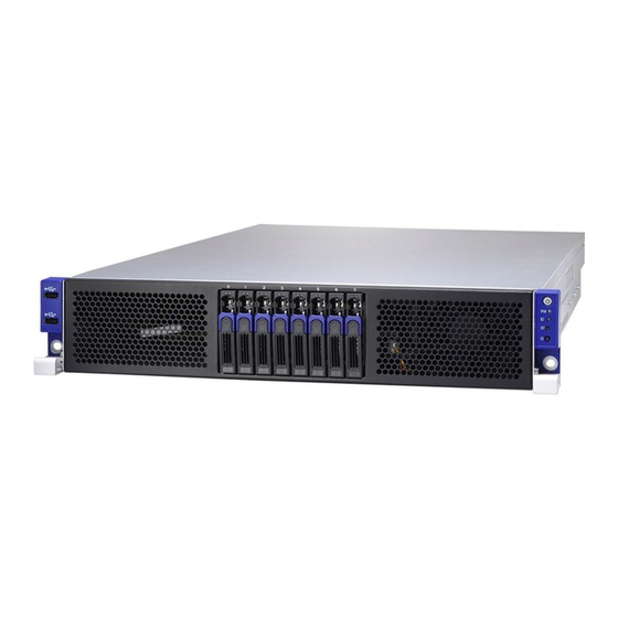
About the Product The following views show you the product. 1.5.1 System Front View Image-1 USB Ports 2.5” HDD bays Power On/OFF Button with Power On/Off LED IPMI LED ID LED RESET Button ID Button http://www.tyan.com... -
Page 23: Led Control And Hdd Led Definitions
Status LED State Description Color: Green Color: Red Solid On Drive present,no activity Green Drive present,with (Blinking) activity Do not care Solid On HDD Fail Blinking Do not care Drive Locate Identify @1Hz Blinking Do not care Rebuilding @4Hz http://www.tyan.com... -
Page 24: System Rear View
1.5.3 System Rear View Image-2 Description (1+1) 1600W Power Supply LAN3 (shared with IPMI)+2 USB2.0 ports ID LED Button ID LED VGA Port LAN1 and LAN2 PCI bracket Expansion Slots http://www.tyan.com... -
Page 25: Lan And Id Led Definitions
Solid Green Solid Yellow 1000 Mbps Link Blinking Green Solid Yellow (1Gbps) Active NOTE: “Left” and “Right” are viewed from the rear panel. ID LED Status Behavior Remark Color Normal ID LED Blue Local and Located Solid on remote http://www.tyan.com... -
Page 26: Motherboard (S7061) Layout
1.5.5 Motherboard (S7061) layout NOTES: "▲" indicates the location of "Pin 1". Jumpers not indicated are for testing only. http://www.tyan.com... - Page 27 3PHD_11 BMC Reset Jumper ID LED BTN1 ID LED Switch Button ID LED ID LED CLEAR_BTN1 Clear CMOS Reset Button SATA1/SATA2 SATA3.0 Connector Jumper Legend OPEN - Jumper OFF Without jumper cover CLOSED - Jumper ON With jumper cover http://www.tyan.com...
-
Page 28: System Top View
1.5.6 System top view Number Description LED Control Board HDD Cage HDD backplane Board System Fan Power Supply http://www.tyan.com... -
Page 29: Block Diagram
1.5.7 Block Diagram http://www.tyan.com... - Page 30 NOTE http://www.tyan.com...
-
Page 31: Chapter 2: Setting Up
Caution! To avoid damaging the motherboard and associated components, do not use torque force greater than 7kgf/cm (6.09 lb/in) on each mounting screw for motherboard installation. Do not apply power to the board if it has been damaged. http://www.tyan.com... -
Page 32: Precautions
Working on a system that is connected to a power supply can be extremely dangerous. Follow the guidelines below to avoid damage to TA77-B7061 or injury to yourself. Ground yourself properly before removing the top cover of the system. -
Page 33: Installing Motherboard Components
CPUs, memory modules, HDD and Add On cards. 2.1.1 Removing the Chassis Cover Follow these instructions to remove the TA77-B7061 chassis cover. Release the screw on the back side. Remove the top screw on the chassis cover and slide the chassis cover in the direction of arrow. - Page 34 After slide the chassis cover while the chassis was look like below. http://www.tyan.com...
-
Page 35: Installing Hard Drives
2.1.2 Installing Hard Drives The TA77-B7061 supports (8) 2.5” hard drives. Follow these instructions to install a hard drive. Warning!!! Always install the hard disk drive to the chassis after the chassis is secured on the rack. Press the locking lever latch in the direction of arrow. - Page 36 Slide the drive tray out. Remove the 4 screws to detach HDD tray bracket. Place a hard drive into the drive tray. Use four screws to secure the HDD. http://www.tyan.com...
- Page 37 Reinsert the HDD tray into the chassis. Press the locking lever to secure the hard drive. Repeat the same procedures to install other HDD trays. http://www.tyan.com...
-
Page 38: Installing The Cpu And Heatsink
2.1.3 Installing the CPU and Heatsink Follow the steps below to install the processor and heatsink. Install the CPU Locate the CPU socket. Pull the CPU lever up to unlock the CPU socket. http://www.tyan.com... - Page 39 Open the socket to a fully open position. Take off the CPU Socket protection cap. Place the CPU in the CPU socket. Make sure the gold arrow is located in the right direction. http://www.tyan.com...
- Page 40 Close the socket and press the CPU socket lever down to secure the CPU. http://www.tyan.com...
- Page 41 Install the heatsink Place the heatsink on top of the CPU and secure it with 4 screws. Secure the heatsink in the direction of the picture shown. http://www.tyan.com...
-
Page 42: Installing The Memory
Press the memory slot locking levers in the direction of the arrows as shown in the following illustration. Align the memory module with the slot. When inserted properly, the memory slot locking levers lock automatically onto the indentations at the ends of the module. http://www.tyan.com... - Page 43 Recommended Memory Population Table http://www.tyan.com...
- Page 44 Recommended Memory Population Table ® To achieve the best performance, TYAN strongly recommended memory installation configuration as listed below: Single CPU Dual CPU Installed installed (CPU0 only) (CPU0 and CPU1) Quantity of memory installed CPU0_DIMM(1)D0 √ √ √ √ √...
- Page 45 The speeds are estimated targets and will be verified through simulation. For 3SPC/3DPC -Rank Multiplication (RM) >= 2. DDP -Dual Die Package DRAM stacking. P –Planer monolithic DRAM Die. Romley-EP/EX platform does not support 3DPC when using E5-2400 LRDIMMs. http://www.tyan.com...
- Page 46 Command Address Timing is 1N. QR RDIMM are supported but not validated by Intel/PMO in a homogenous environment. The coverage will have limited system level testing, no signal integrity testing, and no interoperability testing. The passing QR RDIMMs will be web posted. http://www.tyan.com...
-
Page 47: Installing The Add-On Card
2.1.5 Installing the Add-On Card The TA77-B7061 has one preinstalled M2091-R riser card, You can install an Add-On card into the expansion slot which is available with riser card. The following instructions are for Add-On card installation. You may refer to the procedures below for the installation. - Page 48 Insert the Add-On card as shown. Push the tab of PCI slot in the direction as shown to fix the Add-On card. http://www.tyan.com...
-
Page 49: 2.2 Rack Mounting
19” rack. NOTE: Before mounting the TYAN TA77-B7061 in a rack, ensure that all internal components have been installed and that the unit has been fully tested. However, to make the installation easier, we suggest that you remove all HDD trays before you insert the chassis to the rack. - Page 50 Use two screws to secure the rail onto the rack. Repeat the same procedures for the other rail. Draw out the inner rails from rail assembly. Install inner rails to left and right sides of chassis. http://www.tyan.com...
- Page 51 Then push the whole system into the rack. Push the chassis back into the rack. Secure the mounting ears of chassis to the rack with 2 M5-15L screws. http://www.tyan.com...
-
Page 52: Removing The Server From A Rack
2.2.2 Removing the Server from a Rack Follow these instructions to remove the TYAN TA77-B7061 from an industry standard 19” rack. Remove the two screws from the chassis. Push forward the locking tabs on both rails to unhook the chassis from the rails. - Page 53 Follow the steps described earlier in reverse to remove the chassis from the rack. To avoid injury, it is strongly recommended that two people lift the TYAN TA77-B7061 into the place while a third person screws it to the rack. http://www.tyan.com...
- Page 54 NOTE http://www.tyan.com...
-
Page 55: Chapter 3: Replacing Pre-Installed Components
This chapter explains how to replace the pre-installed components, including the Motherboard, Front panel board, USB board, SATA HDD backplane, M2207-R32-2F and M2208-L32-2F PCI-E Riser card, System fans, Power Distribution board and Power supply unit etc. 3.0.2 Disassembly Flowchart The following flowchart outlines the disassembly procedure. http://www.tyan.com... - Page 56 NOTE http://www.tyan.com...
-
Page 57: Removing The Cover
Before replacing any parts you must remove the chassis cover. Follow Section 2.1.1 Removing the Chassis Cover (page 33) to remove the cover of the TA77-B7061. Replacing the Front Panel Board Follow these instructions to replace the M1701T70-FP Front Panel Board. - Page 58 Remove the Front Panel Board cover. Unscrew the Front Panel Board to replace a new one. Follow the steps described earlier in reverse to reinstall the USB Board. http://www.tyan.com...
-
Page 59: Front Panel Board Specifications
Power On/Off LED Color: Green (after power on) ID LED Color: Blue LEDs Warning (IPMI) LED Dual Color: Yellow (Warning) / Green(Normal) RESET button Push buttons ID button Power On/Off button with Power On/Off LED http://www.tyan.com... -
Page 60: Fpb Connector Pin Definition
3.2.2 FPB Connector Pin Definition J1: FPIO connector Definition Definition PW_LED+ +5VSB ID_LED+ PW_LED- ID_LED- HD_LED+ LED_FAULT1- HD_LED- LED_FAULT2- PWR_SW+ LAN_ACT PWR_SW- LAN_LINK# RESET+ SMB_DAT RESET- SMB_CLK ID_SW- Temp_sensor SMB_ALR FPB_HDD_ACTIVITY_G- SMB_CLK FPB_HDD_FAULT_R- SMB_DAT http://www.tyan.com... -
Page 61: Replacing The Usb Board
Replacing the USB Board Follow these instructions to replace the M1702T70-USB Board. Unscrew to release the USB front cover. Remove the USB front cover. http://www.tyan.com... - Page 62 Unscrew the USB Board. Disconnect the USB Board to replace a new one. Follow the steps described earlier in reverse to reinstall the USB Board. http://www.tyan.com...
-
Page 63: Usb Board Specifications
USB Board Connector Pin Definition J2: 2x5-pin Connector for FP Connector of Motherboard Definition Description Definition Description VCC_USB USB power VCC_USB USB power USB_P0_N Port1(J1) USB- USB_P1_N Port2(J3) USB- USB_P0_P Port1(J1) USB+ USB_P1_P Port2(J3) USB+ GND1 Ground GND2 Ground No connect http://www.tyan.com... -
Page 64: Replacing The System Fan
Replacing the System Fan Follow these instructions to replace the cooling fans in your system. Locate the cooling fans in your system. Unplug the cables connected to the mainboard and lift the fan up from the chassis. http://www.tyan.com... - Page 65 http://www.tyan.com...
- Page 66 Follow Step A & B to unlock the fans and to replace a new one. 40x28mm Fan Step A Step B Step C http://www.tyan.com...
- Page 67 After replacing the new fans, follow Step A & B in reverse order to lock the fans. Reinstall the fans into the chassis. Connect the fan cables to the mainbone fan connectors. http://www.tyan.com...
-
Page 68: Replacing The M1244G70-Bp6-8 Hdd Backplane
Replacing the M1244G70-BP6-8 HDD Backplane Disconnect the power cables and Mini SAS cable connected to the HDD Backplane. Remove the two screws securing the bracket to the chassis base. http://www.tyan.com... - Page 69 Unlock the plastic cable locker and lift the bracket up from the chassis. Unscrew the HDD Backplane from the bracket. Replace a new HDD Backplane and reinstall it into the chassis following the steps mentioned earlier in reverse. http://www.tyan.com...
-
Page 70: M1244G70-Bp6-8 Hdd Backplane Features
M1244G70-BP6-8 HDD Backplane Features Front View Form Factor 8-Layer PCB (1) To S7027GM3NR-LNV mini-SAS connector (1) To add-on card mini-SAS connector Integrated I/O (1) 4x2 pin Power connector (1) 5x2 K8 pin JTAG connector http://www.tyan.com... - Page 71 Rear View Form Factor 8-Layer PCB Integrated I/O (8) SAS HDD Connectors http://www.tyan.com...
-
Page 72: M1244G70-Bp6-8 Connector Pin Definitions
3.5.2 M1244G70-BP6-8 Connector Pin Definitions Definition Definition +12V +12V +12V +12V J11 (CN8) Definition Definition CPLD_JTAG_TCK CPLD_JTAG_TDO VDD_3P3_RUN CPLD_JTAG_TMS CPLD_JTAG_TDI http://www.tyan.com... -
Page 73: Replacing Pci-E Riser Cards
Follow the instructions below to disassemble the M2207-R32-2F, M2208-L32-2F and M2091-R PCI-E riser cards. There are two PCI bracket in the TA77-B7061 chassis. Remove the 8 screws to take out the PCI brackets. Lift the PCI bracket up as show in the image. - Page 74 Unscrew the M2208-L32-2F riser card to replace a new one if necessary. Unscrew the M2091-R riser card to replace a new one if necessary. http://www.tyan.com...
- Page 75 Follow the same procedure to detach the other PCI bracket. Unscrew the M2207-R32-2F riser card to replace a new one if necessary. Follow the steps described earlier in reverse to reinstall the M2207-R32-2F riser card. http://www.tyan.com...
-
Page 76: Replacing M7061T77-D-Power Distribution Board
Replacing M7061T77-D-Power Distribution Board The TA77-B7061 has one pre-installed power distribution board. Follow Follow these instructions to replace the M7061T77-D-Power Distribution Board. Disconnect the power cables attached to the Power Distribution Board. Unscrew the power distribution board. http://www.tyan.com... -
Page 77: M7061T77-D-Power Distribution Board. Features
Form Factor 130*76MM,T=2 mm, 6-Layer PCB (1) 2x4 pin PW connector1 (1) 2x4 pin PW connector2 Integrated I/O (1) 2x4 pin PW connector3 (1) 2x4 pin PW connector4 (1) 2x12 pin PW connector5 http://www.tyan.com... -
Page 78: M7061T77-D-Pdb Connector Pin Definitions
3.7.2 M7061T77-D-PDB Connector Pin Definitions PW1/PW2/PW3/PW4 Definition Definition +12V +12V +12V +12V Definition Definition +12V +12V +12V +12V +12V +12V +12V +12V +12V +12V +12V +12V http://www.tyan.com... -
Page 79: Replacing M7061T77-D-Pbp
Replacing M7061T77-D-PBP The TA77-B7061 has one pre-installed Power Backplane. Follow Follow these instructions to replace the M7061T77-D-Power Distribution Board. Disconnect the power cables attached to the Power backplane. Remove the 4 screws from the power distribution board and lift it from the chassis. -
Page 80: M7061T77-D-Power Backplane. Features
3.8.1 M7061T77-D-Power BackPlane. Features Front view Rear view Form Factor 81*76MM,T=2 mm, 10-Layer PCB (1) Power inlet connector <J1> Integrated I/O (1) Power inlet connector <J2> (1) Signal connector <J3> http://www.tyan.com... -
Page 81: M7061T77-D- Pbp Connector Pin Definitions
+12V +12V +12V +12V +12V +12V +12V +12V +12V 12VSB SMART_ON 12LS PRESENT_N PWOK +12VRS RETRUN_S SMB_ALERT PSON_N +12V +12V +12V +12V +12V +12V +12V +12V +12V Definition Definition 12VSB 12VSB 12VSB 12VSB MB_PSON_N 3V3SB PSU_PWOK PSU_SMBALERT PSMI_SCL PSMI_SDA http://www.tyan.com... -
Page 82: Replacing The Power Supply
Replacing the Power Supply The system has two pre-installed 1,600W (80+ Platinum) Power Supply Units. Follow these instructions to replace the power supply units. Press and hold the latch to pull the power supply out. http://www.tyan.com... - Page 83 After replacing a new power supply, press and hold the latch to push the power supply back into the chassis. http://www.tyan.com...
-
Page 84: Removing Motherboard Procedures
Follow these instructions to remove all motherboard cables. Remove the two screws on the left side. Remove the two screws on the other side. http://www.tyan.com... - Page 85 Remove the four screws on the iron bar. Lift the iron bar and located at the S7061 motherboard. http://www.tyan.com...
- Page 86 Disconnect the 24-pin power cable, 8-pin power cables, mini SAS cable and PSMI cable. Disconnect the 4 system fan cables. Disconnect the GPU power cables. http://www.tyan.com...
-
Page 87: Removing The Motherboard
After removing all of the aforementioned cables, follow the instructions below to remove the motherboard from the chassis. Remove the heatsink and processor if installed. Remove the eleven screws securing the motherboard to the chassis. Carefully lift the motherboard from the chassis. http://www.tyan.com... - Page 88 NOTE http://www.tyan.com...
-
Page 89: Chapter 4: Installing Gpu Cards
Chapter 4: Installing GPU Cards The TA77-B7061 supports Five kinds of Add-On cards. They are NVIDIA M2090 GPU card, NVIDIA K10/K20 GPU card, INTEL MIC GPU card and full length GPU card. In this chapter we will introduce you how to install the NVIDIA M2090 GPU card and the full length card. - Page 90 Insert the M2090 NVIDIA GPU card onto the M2207-R32-2F riser card. Secure the M2090 NVIDIA GPU card with 3 screws. Before install the PCI bracket back to the chassis, push the iron piece lock to the M2090 location. http://www.tyan.com...
- Page 91 Connect the GPU cable to the NVIDIA GPU card. 6. Put the PCI bracket back to the chassis. http://www.tyan.com...
-
Page 92: Installing The Full Length Gpu Card
Follow these instructions to install Intel full length GPU card in your system. Put the Intel full length bracket on the PCI bracket. Then overturn the bracket. Secure the two screws in the Full length hole. Insert the Intel full length card onto the M2208-L32-2F riser card. http://www.tyan.com... - Page 93 Before install the PCI bracket back to the chassis, push the iron piece lock to the Full length location. NOTE: The Intel full length card is not a real card, it is only a model. The real one is thicker than the model. http://www.tyan.com...
- Page 94 NOTE http://www.tyan.com...
-
Page 95: Appendix I: Fan And Temp Sensors
This section aims to help readers identify the locations of some specific FAN and Temp Sensors on the motherboard. A table of BIOS Temp sensor name explanation is also included for readers’ reference. NOTE: The red dot indicates the location of the sensors. http://www.tyan.com... - Page 96 BIOS Fan Sensor Name Explanation CPU0_FAN Fan speed of CPU0_FAN CPU1_FAN Fan speed of CPU1_FAN SYS_FAN_1 Fan speed of SYS_FAN_1 SYS_FAN_2 Fan speed of SYS_FAN_2 SYS_FAN_3 Fan speed of SYS_FAN_3 SYS_FAN_4 Fan speed of SYS_FAN_4 SYS_FAN_5 Fan speed of SYS_FAN_5 http://www.tyan.com...
- Page 97 http://www.tyan.com...
- Page 98 NOTE http://www.tyan.com...
-
Page 99: Appendix Ii: Cable Connection Tables
Mini-SAS → Cable-1 Mini-SAS → Cable-2 2X4P HDD PWR → Cable 3. FP Ctrl and USB Cable Front Panel Board (FPB) to S7061 MB Connect to S7061 MB → Control Cable J1(FPB) FPIO1 → USB Cable J2(USB BP) USB1 http://www.tyan.com... - Page 100 PWR Cable-1 2X4P GPU → GPU card PWR Cable-2 7. 2X4P GPU PWR Cable S7061 MB to GPU Card S7061 MB Connect to GPU Card 2X4P GPU → GPU card PWR Cable-1 2X4P GPU → GPU card PWR Cable-2 http://www.tyan.com...
-
Page 101: Appendix Iii: Fru Parts Table
FRU-CS-0050 422T47800007 CABLE,650mm 2*3P GPU card POWER FRU-CS-0060 422T47800008 CABLE,650mm 2*4P GPU card POWER FRU-CS-0030 422T47800002 CABLE,350mm Cable 2*3P GPU card POWER FRU-CS-0040 422T47800006 CABLE,350mm CCBL-0317 332810000397 A/C Power Cord, L=1800mm,US type CCBL-0300 332810000281 A/C Power Cord, L=1830mm,EU type http://www.tyan.com... - Page 102 NOTE http://www.tyan.com...
-
Page 103: Appendix Iv: Technical Support
MiTAC serves multiple market segments with the industry’s most competitive services to support them. TYAN's tech support is some of the most impressive we've seen, with great response time and exceptional organization in general.” — Anandtech.com Please feel free to contact us directly for this service at tech-support@tyan.com... - Page 104 (RMA) number. The RMA number should be prominently displayed on the outside of the shipping carton and the package should be mailed prepaid. TYAN will pay to have the board shipped back to you. ® TYAN TA77-B7061 Service Engineer’s Manual V1.0 Document No.:...
Need help?
Do you have a question about the TA77-B7061 and is the answer not in the manual?
Questions and answers