Table of Contents
Advertisement
Quick Links
Advertisement
Table of Contents

Related Manuals for TYAN TA70-B8237


Summary of Contents for TYAN TA70-B8237
- Page 1 TA70-B8237 Service Engineer’s Manual http://www.tyan.com...
- Page 2 http://www.tyan.com...
- Page 3 Neither this manual, nor any material contained herein, may be reproduced without written consent of manufacturer. ® Copyright 2013 MiTAC International Corporation. All rights reserved. TYAN a registered trademark of MiTAC International Corporation. Version 1.0 Disclaimer Information contained in this document is furnished by MiTAC International Corporation and has been reviewed for accuracy and reliability prior to printing.
- Page 4 There will be danger of explosion if battery is incorrectly replaced. Replace only with the same or equivalent type recommended by manufacturer. Dispose of used battery according to manufacturer instructions and in accordance with your local regulations. http://www.tyan.com...
-
Page 5: About This Manual
About this Manual This manual provides you with instructions on installing your TYAN TA70-B8237. This Manual is intended for experienced users and integrators with hardware knowledge of personal computers. This manual consists of the following parts: Chapter 1: Provides an introduction to the TYAN TA70-B8237... -
Page 6: Safety And Compliance Information
Safety and Compliance Information Before installing and using TYAN TA70-B8237, take note of the following precautions: ·Read all instructions carefully. ·Do not place the unit on an unstable surface, cart, or stand. ·Do not block the slots and opening on the unit, which are provided for ventilation. -
Page 7: Safety Information
You must become familiar with the safety information in this guide before you install, operate, or service TYAN products. Symbols on Equipment Caution. This symbol indicates a potential hazard. - Page 8 · Make sure racks are coupled together if it is a multiple-rack installation. · Make sure the rack is level and stable before installing an appliance in the rack. · Make sure the leveling jacks are extended to the floor. http://www.tyan.com...
- Page 9 If you do not ground the Green/Yellow tab, it can cause an electrical shock due to high leakage currents. · Do not place objects on AC power cords or cables. Arrange them so that no http://www.tyan.com...
- Page 10 TYAN, your authorized TYAN partner, or their agents. Equipment Modifications · Do not make mechanical modifications to the system. TYAN is not responsible for the regulatory compliance of TYAN equipment that has been modified.
- Page 11 – Liquid has been spilled on the product or an object has fallen into the product. – The product has been exposed to rain or water. – The product has been dropped or damaged. – The product does not operate normally when you follow the operating instructions. http://www.tyan.com...
- Page 12 http://www.tyan.com...
-
Page 13: Table Of Contents
Table of Contents Chapter 1: Overview............... 17 About the TYAN TA70-B8237 ..........17 Product Models............... 17 Features.................. 18 Standard Parts List ..............20 1.4.1 Box Contents ..............20 1.4.2 Accessories ..............22 About the Product..............23 1.5.1 System Front View ............23 1.5.2... - Page 14 5.3.11 Serial Port Console Redirection ........121 Chipset Menu ............... 122 5.4.1 North Bridge ..............123 5.4.2 South Bridge..............124 5.4.3 OnBoard Device Configuration........126 Boot ..................127 Security................. 129 Server Management ............. 130 Save & Exit ................132 http://www.tyan.com...
- Page 15 Chapter 6: Diagnostics ..............135 Flash Utility ................135 AMIBIOS Post Code (Aptio) ..........136 Appendix I: Cable Connection Tables ........145 Appendix II: Temp Sensors ............147 Appendix III: FRU Parts Table ............. 149 Appendix IV: Technical Support ..........151 http://www.tyan.com...
- Page 16 NOTE http://www.tyan.com...
-
Page 17: Chapter 1: Overview
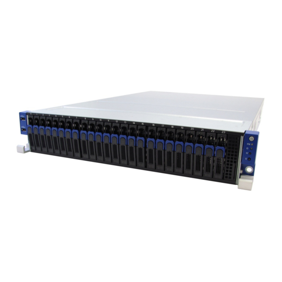
® TYAN also offers the TA70-B8237 in a version that can support up to (24) 2.5” hot-swap hard drives and two 2.5” internal hard drives. The TA70-B8237 uses TYAN’s latest chassis featuring a robust structure and a solid mechanical enclosure. -
Page 18: Features
Features TYAN TA70B8237 (B8237T70V24HR) Form Factor 2U Rackmount Gross Weight 31 kg Chassis Model TA70 System Dimension (D x W x 27.56" x 17.17" x 3.43" (700 x 436 x 87mm) Motherboard S8237PN Buttons (1) PWR / (1) RST / (1) ID... - Page 19 (2) FRU-TH-0070, CPU PASSIVE-HEATSINK Rail kit (1) sliding rail kit Package Manual (1) Quick Installation Guide Contains Installation CD (1) TYAN installation CD (2) CCBL-0300, EU type power cord / (2) CCBL-0317, US Cable Power Cord type power cords http://www.tyan.com...
-
Page 20: Standard Parts List
Standard Parts List This section describes TA70-B8237 package contents and accessories. Open the box carefully and ensure that all components are present and undamaged. The product should arrive packaged as illustrated below. 1.4.1 Box Contents Component Description (1) 2U Barebone (24) 2.5”... - Page 21 (2) 6038 System Fans (2) M2212-R16-2F Riser Card (pre-installed) (1) M1807TA7-FB Fan Board (pre-installed) (3) M1256T70-BP6-8 HDD Backplane Board (1) M1702T70-USB USB Board http://www.tyan.com...
-
Page 22: Accessories
® TYAN ’s website for service: http://www.tyan.com ® The web site also provides information of other TYAN products, as well as FAQs, compatibility lists, BIOS settings, etc. CPU Heatsink x 2 Air Duct x 1 Quick Installation Guide x 1... -
Page 23: About The Product
About the Product The following views show you the product. 1.5.1 System Front View USB Connectors Front Control Panel 2.5” Hot-Swap HDD Bays M1701T70-FPB (Front Control Panel) Power On/Off Button with LED IPMI LED ID LED Reset Button ID Button http://www.tyan.com... -
Page 24: System Rear View
1.5.2 System Rear View PCI Expansion Slot 750W Power Supply Debug Header ID LED USB Port LAN3 (shared with IPMI) http://www.tyan.com... -
Page 25: Led Definitions
ID LED will light blue if the system is identified. Users from remote sites can also activate the ID LED by entering a few commands in IPMI. For detailed software support, please visit the Broadcom website for the latest Broadcom 5725 user guide. http://www.tyan.com... - Page 26 Color Description Solid On Drive present, no activity Activity LED Green Blinking Drive present, with activity Solid On HDD Failed Blinking Status LED Identify @1Hz Blinking Rebuild @4Hz NOTE: HDD LED behavior may vary with different SAS RAID cards. http://www.tyan.com...
- Page 27 (Speed) (Link/Activity) Link Green Solid On 10 Mbps Active Blinking Green Link Solid Green Green Solid On 100 Mbps Active Solid Green Blinking Green Link Solid Yellow Green Solid On 1000 Mbps Active Solid Yellow Blinking Green No Link http://www.tyan.com...
-
Page 28: System Top View
(3) 6056 System Fans + (2) 6038 System Fans (1) M1807TA7-FB Fan Board (pre-installed) System Main Board (1) Power Supply Module (1) Internal 2.5” HDD bay for 2 pcs. 2.5” HDD (2) M2212-R16-2F Riser card (1) Power Supply Module http://www.tyan.com... -
Page 29: Chapter 2: Setting Up
Caution! To avoid damaging the motherboard and the associated components, do not use torque force greater than 7kgf/cm (6.09 lb/in) on each mounting screw for motherboard installation. Do not apply power to the board if it has been damaged. http://www.tyan.com... -
Page 30: Precautions
Working on a system that is connected to a power supply can be extremely dangerous. Follow the guidelines below to avoid damage to TA70-B8237 or injury to yourself. Ground yourself properly before removing the top cover of the system. -
Page 31: Removing And Installing The Chassis Cover
Removing and Installing the Chassis Cover Follow these instructions to remove the TA70-B8237 chassis cover. Unless you are installing a hot-swappable component, be sure to turn off the system, disconnect all attached peripherals and disconnect the system from the electrical source. - Page 32 Lift to remove the air duct. To install the chassis cover, follow the above steps in reverse order. http://www.tyan.com...
-
Page 33: Installing Motherboard Components
2. Push down the lever (1) and slightly pull away from the socket (2) to release the latch, and then lift up the lever to a fully open position (3). Do the same procedures to release the other lever. http://www.tyan.com... - Page 34 3. Lift the CPU socket cover to a fully open position. 4. Remove the protection cap from the CPU socket. 5. Place the CPU into the socket making sure that the gold arrow is located in the right direction. http://www.tyan.com...
- Page 35 7. Pull down the lever (1), press down (2) and hook towards the latch (3). Repeat the same procedures to hook the other lever. 8. Position the heatsink on top of the CPU and secure it with 2 screws. 9. Repeat steps 2 to 8 to install the second CPU and heatsink. http://www.tyan.com...
-
Page 36: Installing The Expansion Cards
2.3.2 Installing the Expansion Cards TA70-B8237 comes with two PCI-E riser brackets with two pre-installed PCI-E x16 riser cards. The two PCI-E riser cards connect to the two PCI-E slots on the mainboard. (2) PCI-E x16 slot direction (x8 link) Follow these instructions to install expansion cards. - Page 37 Unscrew the PCI dummy bracket. Slide to remove the PCI dummy bracket. Insert the expansion card to the riser bracket. Make sure the expansion card is connected to the PCI-E slot on the riser card and properly latched onto the riser bracket. http://www.tyan.com...
- Page 38 Insert the riser cards to the PCI-E slots on the main board as you align the riser bracket onto the chassis. Attach the 2 screws to secure the riser bracket to the chassis. Repeat the above procedures to install another expansion card. http://www.tyan.com...
- Page 39 Note: The bottom slot only has power and no signal. The label will be placed over the PCI-E slot. http://www.tyan.com...
-
Page 40: Installing The Memory
Align and insert the memory module down onto the slot. When inserted properly, the memory slot locking levers lock automatically on the indentations at the ends of the module. Follow the recommended memory population table to install the other memory modules. http://www.tyan.com... - Page 41 Memory Population Option Table The following pictures show common types of DDR3 memory modules. http://www.tyan.com...
- Page 42 4. Dual-rank DIMMs are recommended over single-rank DIMMs. 5. Un-buffered DIMM can offer slightly better performance than registerd DIMM if populating only a single DIMM per channel. 6. Always install with CPU0 Socket and DIMM_2 Slot first, following the alphabetical order. http://www.tyan.com...
- Page 43 √ √ CPU1_DIMM_A2 √ √ CPU1_DIMM_B0 √ CPU1_DIMM_B1 √ √ √ √ √ √ CPU1_DIMM_B2 √ √ CPU1_DIMM_C0 √ CPU1_DIMM_C1 √ √ √ √ √ √ √ √ CPU1_DIMM_C2 √ √ CPU1_DIMM_D0 √ CPU1_DIMM_D1 √ √ √ √ CPU1_DIMM_D2 http://www.tyan.com...
- Page 44 Table 2 lists valid DIMM configurations. SR is Single Rank, DR is Dual Rank, and QR is Quad Rank. For DIMM speed limitations of different configurations. http://www.tyan.com...
-
Page 45: Installing Imc Card
Locate the IMC card slot on the motherboard. Insert the IMC card into the slot in the direction of the arrow as shown in the following illustration, and press down to lock it in place. Attach the screw to secure the IMC card onto the motherboard. http://www.tyan.com... - Page 46 IMC Card Features Top Side Bottom Side http://www.tyan.com...
-
Page 47: Installing Mezz Card
Align the IO connector of the Mezz card to the IO connector slot of the chassis and then press the Mezz card down to install it on the motherboard. Attach the four (4) screws to secure the Mezz card onto the motherboard. http://www.tyan.com... - Page 48 Mezz Card Features Top Side Bottom Side http://www.tyan.com...
-
Page 49: Installing Hard Drives
2.3.6 Installing Hard Drives The TA70-B8237 can support up to (26) 2.5” hard drives. Installing 2.5” Hot-Swap Hard Drives Follow these instructions to install a 2.5” hot-swap HDD. Warning!!! Always install the hard disk drive to the chassis after the chassis has been secured on the rack. - Page 50 Unscrew the 4 screws securing the HDD bracket to the HDD tray. Place the 2.5” hard disk drive into the HDD tray and secure the HDD to the HDD tray using 4 screws. Reinsert the HDD tray into the chassis. http://www.tyan.com...
- Page 51 Push to secure the locking lever until it clicks into place. http://www.tyan.com...
- Page 52 Removing and Installing the Chassis Cover on page 31 for instructions on how to remove and reinstall the chassis cover. Remove screw securing the HDD bracket on top of the power supply unit. Slide to remove the HDD bracket. http://www.tyan.com...
- Page 53 Secure the HDD rubber to each of the HDD screw holes. Align the HDD to the HDD bracket screw holes and secure the 4 screws. Slide the HDD bracket and secure the screw. http://www.tyan.com...
-
Page 54: Rack Mounting
Mounting Ears Screw Pack x 1 2.4.1 Installing the Server in a Rack Follow these instructions to mount the TYAN TA70-B8237 into an industry standard 19” rack. NOTE: Before mounting the TYAN TA70-B8237 in a rack, ensure that all internal components have been installed and that the unit has been fully tested. - Page 55 Align the inner sliding rail (1) on the side of the server, and pull towards the arrow (2) to secure the three hooks. Secure the inner sliding rail to the server. Repeat steps 2 to 3 to secure the sliding rail to the other side of the server. http://www.tyan.com...
- Page 56 Secure the outer rails to the rack using four M5 screws and four washers (B) on each side. Rack Mounting the Server Pull out the middle rail to the latch position. Lift the unit and then insert the inner slide rails into the middle rails. http://www.tyan.com...
- Page 57 When the inner rails come to a stop, pull the tab to release the latch and push the whole system in. Secure the mounting ears of the unit to the rack using two M5 x 20L screws (A). http://www.tyan.com...
- Page 58 NOTE http://www.tyan.com...
-
Page 59: Chapter 3: Replacing Pre-Installed Components
This chapter explains how to replace the pre-installed components, including the S8237 Motherboard, M1701T70-FPB Front Panel Board, M1702T70-USB USB Board, M1256T70-BP6-8 HDD Backplane Board, M1807-FB Fan Board, PCI-E Riser Card, System Fan and Power Supply Unit etc. Disassembly Flowchart The following flowchart outlines the disassembly procedures. http://www.tyan.com... -
Page 60: Replacing The System Fan
Follow these instructions to remove the system fan. Remove the chassis cover (see 2.2 Removing and Installing the Chassis Cover on page 31). Lift the fan handle. Lift the system fan from the chassis. Follow the above procedures in reverse order to replace the system fans. http://www.tyan.com... -
Page 61: Replacing The Fan Board
Replacing the System Fan on page 60). Disconnect the fan board connectors. Unscrew the 9 screws and lift to remove the fan board. Replace the fan board and follow the above procedures in reverse order reinstall the fan board. http://www.tyan.com... -
Page 62: Fan Board Features
3.3.1 Fan Board Features Fan Connector (J1) Fan Connector (J2) Fan Connector (J3) Fan Connector (J4) Fan Connector (J5) Signal Connector (J6) Power Connector (PW1) 3.3.2 Pin Definitions PW1: Power Inlet Connector Definition Definition http://www.tyan.com... - Page 63 Tach 5 Tach 2 Tach 6 Tach 3 Tach 7 Tach 4 Tach 8 Tach 9 Tach 10 PWM 2 PWM 1 Tach 11 Tach 12 V3AUX PWM 3 J1~J5: Fan Connector Definition PWM1 VCC12 TACH1 TACH2 VCC12 PWM2 http://www.tyan.com...
-
Page 64: Replacing The Front Panel Board
Turn off the system, disconnect all attached peripherals and disconnect the system from the electrical source. Remove the three screws securing the front panel board to the chassis. Pull to remove the front panel bracket and cover. Remove the screw securing the front panel board. http://www.tyan.com... - Page 65 Slightly pull the front panel board away from the chassis and then lift to remove the front panel board. Disconnect the front panel connector. Replace the front panel board and follow the above procedures in reverse order to reinstall the front panel board. http://www.tyan.com...
-
Page 66: Front Panel Board Features
3.4.1 Front Panel Board Features 2x15-pin Header (J1) Power On/Off Button/LED (green) IPMI LED (amber) ID LED (blue) Reset Button (SW3) ID Button (SW2) http://www.tyan.com... -
Page 67: Pin Definitions
3.4.2 Pin Definitions J1: 2x15-pin Front Panel Header Definition Definition PWD_LED+ +5VSB ID_LED+ PW_LED- ID_LED- HDD LED+ LED_FAULT1- HDD LED- SYS_FAULT2- PWR_SW+ LAN_ACT PWR_SW- LAN_LINK# RESET+ SMB_DAT RESET- SMB_CLK ID_SW- TEMP_SENSOR SMB_ALR FPB_HDD_ACTIVITY_G- SMB_CLK FPB_HDD_FAULT_R- SMB_DAT http://www.tyan.com... -
Page 68: Replacing The Usb Board
Turn off the system, disconnect all attached peripherals and disconnect the system from the electrical source. Remove the three screws securing the USB panel to the chassis. Pull to remove the USB panel bracket and cover. Remove the screw securing the USB board. http://www.tyan.com... - Page 69 Slightly pull the USB board away from the chassis. Disconnect the USB board connector. Replace the USB board and follow the above procedures in reverse order to reinstall the USB board. http://www.tyan.com...
-
Page 70: Usb Board Features
3.5.1 USB Board Features USB Port (J3) 2x5-Pin Header (J2) USB Port (J1) 3.5.2 Pin Definitions J2: 2x5-Pin Header Definition Definition VCC_USB VCC_USB USB_P0_N USB_P1_N USB_P0_P USB_P1_P GND1 GND2 http://www.tyan.com... -
Page 71: Replacing The Hdd Backplane Board
Remove the chassis cover (see 2.2 Removing and Installing the Chassis Cover on page 31). Remove all the hot-swap HDD bays. Disconnect the power and SAS cables. Remove the 9 screws securing the HDD backplane board bracket to the chassis. http://www.tyan.com... - Page 72 Remove the 18 screws securing the HDD backplane board to the HDD backplane board bracket. Lift the HDD backplane board to remove it from the HDD backplane board bracket. Replace the HDD backplane board and follow the above procedures in reverse order to reinstall the HDD backplane board. http://www.tyan.com...
-
Page 73: Hdd Bp Board Features
(J1, J2, J4, J9, J6, J7, J10,J12) 2x4 Power Connector (PW3) Mini SAS Connector (SAS_1) Mini SAS Connector (SAS_0) HDD LED Connector (LED4~LED7) (J15) HDD LED Connector (LED4~LED7) (J14) JTAG (J13) FW Burning Connector Form Factor: 134.4 x 76.8 mm http://www.tyan.com... -
Page 74: Connector Pin Definitions
Connector Pin Definitions J13: JTAG Definition Definition JTAG_TCK JTAG_TD0 VCC3_3 JTAG_TMS JTAG_TD1 J14: HDD LED Connector Definition Definition HD0_GREENLED HD0_REDLED HD1_GREENLED HD1_REDLED HD2_GREENLED HD2_REDLED HD3_GREENLED HD3_REDLED J15: HDD LED Connector Definition Definition HD4_GREENLED HD4_REDLED HD5_GREENLED HD5_REDLED HD6_GREENLED HD6_REDLED HD7_GREENLED HD7_REDLED http://www.tyan.com... -
Page 75: Replacing The Power Supply Unit
Position the power supply unit handle. To remove the power supply, press the lever as you pull by the handle. Pull the power supply unit completely out from its bay. Follow the above procedures in reverse order to replace the power supply unit. http://www.tyan.com... -
Page 76: Replacing The Motherboard
Remove the two power supply units from the chassis (see 3.7 Replacing the Power Supply Unit on page 75). Remove the two riser brackets (see 2.3.2 Installing the Expansion Cards on page 36). Disconnect all the cables connected to the motherboard. http://www.tyan.com... - Page 77 Unscrew the two thumb screws securing the motherboard to the chassis. Slide the motherboard towards the front, then lift to remove the motherboard from the chassis. Prepare a new motherboard. Set the necessary jumpers. http://www.tyan.com...
- Page 78 NOTE http://www.tyan.com...
-
Page 79: Chapter 4: Mainboard Information
Caution! To avoid damaging the motherboard and associated components, do not use torque force greater than 7kgf/cm (6.09 lb/in) on each mounting screw for motherboard installation. Do not apply power to the board if it has been damaged. http://www.tyan.com... -
Page 80: Board Image (S8237)
Board Image (S8237) S8237 This picture represents the latest board revision available at the time of publishing this manual. The board you have received may not look exactly like the above picture. http://www.tyan.com... -
Page 81: Pin Definitions
To make sure the BMC can work normally in Sleep 5 state, PSU 12VSB should be able to provide MB with around 1.5A continuously current in Sleep 5. To avoid PSU 12VSB over current protection, PSU 12VSB should be able to endure at least 5A (2ms) inrush current when AC on. http://www.tyan.com... - Page 82 PW1 (1 x 4 Pin) Definition Definition +12V PW2 (1 x 4 Pin) Definition Definition +12V PW3 (2 x 8 Pin) Definition Definition PW4 (2 x 2 Pin) Definition Definition http://www.tyan.com...
- Page 83 +12V +12V J50, J51, J52, J53, J54, J56 Serial ATA Connector Definition Definition SATA_TXP0 SATA_TXN0 SATA_RXN0 SATA_RXP0 J97 242 Pin IMC Connector Definition Definition 5V_RUN 3V3_RUN 5V_RUN 3V3_RUN 3V3_DUAL 3V3_RUN 3V3_DUAL 3V3_DUAL 5V_DUAL 3V3_DUAL 5V_DUAL 3V3_DUAL 5V_DUAL 3V3_DUAL 5V_DUAL http://www.tyan.com...
- Page 84 RSVD LPC_DRQ_L PCIE_PRSNT1_L LPC_LFRAME_L PCIE_PRSNT2_L LPC_LAD0 LPC_LAD1 LPC_CLKRUN_L LPC_PME_L LPC_LAD2 LPC_SERIRQ LPC_LAD3 LPC_CLK LPC_RST_L LPC_SMI_L RSVD RSVD RSVD RSVD UART0_TXD UART0_RXD DV1_TX0_H UART0_DSR_L DV1_TX0_L UART0_CTS_L DVI_TX1_H UART0_DCD_L DVI_TX1_L UART0_DTR_L UART0_RTS_L DVI_TX2_H UART0_RI_L DVI_TX2_L UART0_TXD(SoL) DVI_TX_CLK_H UART0_RXD(SoL) DVI_TX_CLK_L RSVD/UART1_DSR_L RSVD/UART1_CTS_L http://www.tyan.com...
- Page 85 12C_SCL4 (Shared) 12C_SDA1(Private1) 12C_SDA4 (Shared) MCARD_AUX_SOL_CTRL_L USB0_P USB0_N USB1_P USB1_N USB_CLK RSVD TAN_TACH0 FAN_TACH5 TAN_TACH1 FAN_TACH6 TAN_TACH2 FAN_TACH7 TAN_TACH3 FAN_PWM_CPU TAN_TACH4 FAN_PWM_SYS_ZONE0 RSVD FAN_PWM_SYS_ZONE1 RGMII_TX_CLK FAN_PWM_PS RMII_TXD0/RGMII_TXD0 FAN_SEL0_L RMII_TXD1/RGMII_TXD1 FAN_SEL1_L RGMII_TXD2 FAN_SEL2_L RGMII_TXD3 FAN_SEL3_L RMII_TX_EN/RGMII_TX_CTL 157 CARD_ID0 RMII_RX_DV/RGMII_RX_CTL 161 CARD_ID1 http://www.tyan.com...
- Page 86 ACOMP_ADC2 PS2_KBD_GATE_A20_L ACOMP_ADC3 PS2_MSE_CLK ACOMP_ADC4 PS2_MSE_DATA ACOMP_ADC5 LAN_MCARD_TX_H LAN_MCARD_RX_H LAN_MCARD_TX_L LAN_MCARD_RX_L LAN_LINK_LED_L CLK_32768 LAN_BUSY_LED_L SYS_ACPI_STATE0 SYS_ACPI_STATE1 SYS_TERMTRIP_L SYS_ACPI_STATE2 SYS_INTRUDER_L VGA_HSYNC SYS_LINE_AC_L VGA_VSYNC SYS_PWRBTN_L VGA_RED SYS_RSTBTN_L SYS_NMIBTN_L VGA_GRN SYS_SMI_L SYS_ALL_PWROK VGA_BLU SYS_PCI_RST_L VGA_DDC_CLK SYS_IO_EXP_INT_L VGA_DDC_DATA MCARD_PWRBTN_L NCSI_TXD0 MCARD_RSTBTN_L NCSI_TXD1 MCARD_NMIBTN_L http://www.tyan.com...
- Page 87 PIN 4 PIN 6 PIN 8 PIN 10 PX_TCK PX_TMS P0_TDI CPUX_TDO HDT_PWROK PIN 11 PIN 13 PIN15 PIN 17 PIN 19 P1_DBRDY P0_VDDIO_RUN PIN 12 PIN 14 PIN 16 PIN 18 PIN 20 HDT_RST_L P0_DBRDY CPU_DBREQ_L PX_TEST19 PX_TEST18 http://www.tyan.com...
- Page 88 J16 2*3 pin BCM5725 Debug Header PIN 1 PIN 2 PIN 3 V3DU Serial_DO PIN 4 PIN 5 PIN 6 Serial_DI J11 2*3 pin BCM5720 Debug Header PIN 1 PIN 2 PIN 3 V3DU Serial_DO PIN 4 PIN 5 PIN 6 Serial_DI http://www.tyan.com...
- Page 89 PIN12 PIN13 PIN14 LOW_HEX_0 LOW_HEX_3 LOW_HEX_2 LOW_HEX_1 J96 TPM&80port 2*8PIN header. PIN 1 PIN2 PIN3 PIN4 PIN5 PIN6 PIN7 PIN8 FRAM LPC_LAD RESE LPC_LAD VCC3 LPC_LAD0 PIN1 PIN1 PIN9 PIN10 PIN11 PIN13 PIN14 PIN15 LPC_LAD LPC_SERIR 33MHZ PRESENT V3DU http://www.tyan.com...
- Page 90 PIN 4 PIN 6 PIN 8 PIN 10 PIN 12 PIN14 PIN16 PIN18 PIN20 PIN 1 PIN 3 PIN 5 PIN 7 PIN 9 PIN11 PIN13 PIN15 PIN17 PIN19 ARBOU 50M_CL ARBIN RXD1 RXD0 CRS_DV RXER TXEN TXD0 TXD1 http://www.tyan.com...
- Page 91 PIN14 PIN15 PIN16 PIN17 PIN18 PIN19 PIN20 SDAT SCLK V3DU System Header JP28 2PIN Power BTN pin header PIN1 PIN2 PWR_BTN- JP29 2PIN cold reset pin header PIN1 PIN2 RESET_BTN- JP30 2PIN warm reset pin header PIN1 PIN2 WARM_REST_HEADER_L http://www.tyan.com...
- Page 92 2PIN TRAFFICLED_L pin header PIN1 PIN2 V3DU TRAFFICLED_L JP16 Intruder Header PIN1 PIN2 INTRUDER_L JP17 TPM&80port Debug Header PIN1 PIN2 TPM_RST_L J28 /J29/J30 BCM5720 FUNC_MODE Select Header PIN1 PIN2 FUNC_MOE V3DU J95 & J100 CPU Power Saving Header PIN1 PIN2 VDD_PSI_L PHASE2_PSI_L http://www.tyan.com...
- Page 93 PIN 1 PIN 2 PIN 3 P1_TDO CPUX_TDO P0_TDO_HDT_TDO JP20 Enable/Disable the second NB Jumper Default:2-3 PIN 1 PIN 2 PIN 3 SECOND_SR5690_SYSRESET_L SR5690_SYSRESET_L JP8 Clear CMOS Jumper Default:1-2 Clear CMOS PIN 1 PIN 2 PIN 3 VBAT SB700_VBAT http://www.tyan.com...
- Page 94 PIN 3 V3DU Chassis configuration JP11&JP12&JP14 COM Debug Jumper JP11 Default:1-2 PIN 1 PIN 2 PIN 3 TXD_SIO IMC_TXD JP12 Default:1-2 PIN 1 PIN 2 PIN 3 RXD_SIO IMC_RXD JP14 Default:1-2 PIN 1 PIN 2 PIN 3 VCC_COM V5SB http://www.tyan.com...
-
Page 95: System Block Diagram (S8237)
System Block Diagram (S8237) http://www.tyan.com... -
Page 96: Mainboard Mechanical Drawing
Mainboard Mechanical Drawing http://www.tyan.com... -
Page 97: Board Parts, Jumpers And Connectors
The board you have received may not look exactly like the above diagram. The DIMM slot numbers shown above can be used as a reference when reviewing the DIMM population guidelines shown later in the manual. For the latest board revision, please visit our web site at http://www.tyan.com. http://www.tyan.com... -
Page 98: Jumpers & Connectors
12V and 5V For HDD Power Connector 5V for HDD backplane 3.3V for a back-plane or other system use PWR2/PWR3/PWR4 12V for HDD backplane PWR5 12V for FAN board U108 System BIOS U118 Super I/O ROM System Clock chip http://www.tyan.com... - Page 99 CPU1 DIMM Slots (Channel A/B) P1_MC[2 0] / P1_MD[2 0] CPU1 DIMM Slots (Channel C/D) Note: 1. P0_MA[2 0] = P0_MA0 , P0_MA1 and P0_MA2. Jumper Legend OPEN - Jumper OFF Without jumper cover CLOSED - Jumper ON With jumper cover http://www.tyan.com...
-
Page 100: Thermal Interface Material
CPU lid (applying too much will actually reduce the cooling). NOTE: Always check with the manufacturer of the heat sink & processor to ensure that the thermal interface material is compatible with the processor and meets the manufacturer’s warranty requirements. http://www.tyan.com... -
Page 101: Tips On Installing The Motherboard In The Chassis
If there are any studs missing, you will know right away since the motherboard will not be able to be securely installed. http://www.tyan.com... - Page 102 Some chassis include plastic studs instead of metal. Although the plastic studs are usable, MiTAC recommends using metal studs with screws that will fasten the motherboard more securely in place. Below is a chart detailing what the most common motherboard studs look like and how they should be installed. http://www.tyan.com...
-
Page 103: Chapter 5: Bios
The table below shows how to navigate in the setup program using the keyboard. Function Left/Right Arrow Keys Change from one menu to the next Up/Down Arrow Keys Move between selections Enter Open highlighted section PgUp/PgDn Keys Change pages Change options Exit http://www.tyan.com... -
Page 104: Getting Help
The following pages provide the details of BIOS menu. Please be noticed that the BIOS menu are continually changing due to the BIOS updating. The BIOS menu provided are the most updated ones when this manual is written. Please visit TYAN’s website at http://www.tyan.com for the information of BIOS updating. -
Page 105: Main Menu
It displays BIOS related information. Memory Information This displays the total memory size. System Date Adjust the system date. MM (Months): DD (Days): YYYY (Years) System Time Adjust the system clock. HH (24 hours format): MM (Minutes): SS (Seconds) Access Level Read only. http://www.tyan.com... -
Page 106: Advanced Menu
PCI, PCI-X and PCI Express Settings. WHEA Configuration Enable Windows Hardware Error Architecture. ACPI Settings System ACPI Parameters. CPU Configuration CPU Configuration Parameters. Runtime Error Logging Enable POST error logging support. IPMI H/W Monitor PC Healt Status. IDE Configuration IDE controller Parameters. http://www.tyan.com... - Page 107 USB Configuration USB Configuration Parameters. Watchdog Timer Configuration Watch Dog Mode. Super IO Configuration Super IO Configuration Parameters. Serial Port Console Redirection Serial Port Console Redirection. http://www.tyan.com...
-
Page 108: Pci Subsystem Settings
5.3.1 PCI Subsystem Settings PCI Common Settings Configure PCI Latency Timer, enable/disable VGA Palette Snoop, PERR# Generation, and SERR# Generation. PCI Express Settings Configure PCI express device settings. PCI Express GEN 2 Settings Configure PCI express GEN device settings. http://www.tyan.com... -
Page 109: Whea Configuration
5.3.2 WHEA Configuration WHEA Support Enable or disable Windows Hardware Error Architechture. Disabled / Enabled http://www.tyan.com... -
Page 110: Acpi Settings
Disabled / Enabled Enable Hibernation Enable or disable System ability to Hibernate (OS/S4 Sleep State). This option may not be effective with some OS. Disabled / Enabled Lock Legacy Resources Enable or disable Lock of Legacy Resources. Disabled / Enabled http://www.tyan.com... -
Page 111: Cpu Configuration
Disabled / Enabled Enable to let the system utilize the AMD specific ACPI states to save power consumption. Disabled / Enabled Enable to let the system utilize the AMD specific ACPI states to save power consumption. Disabled / Enabled http://www.tyan.com... - Page 112 Enable or disable Core C6 state to reduce power consumed by the CPU. Disabled / Enabled HPC Mode Enable or disable High Performance Computing Mode. Disabled / Enabled Socket 0 Information Display information related to Socket 0. Read only. Socket 1 Information Display information related to Socket 1. Read only. http://www.tyan.com...
-
Page 113: Runtime Error Logging
5.3.5 Runtime Error Logging POST Error Logging Support Enable or disable POST Error logging support. Disabled / Enabled Runtime Error Logging Support Enable or disable Runtime Error logging support. Disabled / Enabled http://www.tyan.com... -
Page 114: Ipmi H/W Monitor
5.3.6 IPMI H/W Monitor PC Health Status Displays the PC Health status, such as temp sensors. Read only. http://www.tyan.com... -
Page 115: Ide Configuration
SATA Port 2 Enable or disable the sata port 2. Enabled / Disabled SATA Port 3 Enable or disable the sata port 3. Enabled / Disabled SATA Port 4 Enable or disable the sata port 4. Enabled / Disabled http://www.tyan.com... - Page 116 SATA Port 5 Enable or disable the sata port 5. Enabled / Disabled http://www.tyan.com...
-
Page 117: Usb Configuration
The time-out value for Control, Bulk and Interrupt transfers. 20 sec / 10 sec / 5 sec / 1 sec Device reset time-out USB mass storage device Start Unit command time-out. 20 sec / 10 sec / 30 sec / 40 sec http://www.tyan.com... - Page 118 Maximum time the device will take before it properly reports itself to the Host Controller. AUTO uses default value: for a Root port it is 100 ms, for a Hub port the delay is taken from Hub descriptor. Auto / Manual http://www.tyan.com...
-
Page 119: Watchdog Timer Configuration
Disabled / POST / OS / PowerOn NOTE: Watch Dog Timer will not appear when Watch Dog Mode is set to [Disabled]. Watch Dog Timer Watch Dog Timer Help. 2 MINS / 4 MINS / 6 MINS / 8 MINS / 10 MINS http://www.tyan.com... -
Page 120: 5.3.10 Super Io Configuration
5.3.10 Super IO Configuration Serial Port 0 Configuration Set parameters of serial port 0 (COMA) http://www.tyan.com... -
Page 121: 5.3.11 Serial Port Console Redirection
5.3.11 Serial Port Console Redirection Console Redirection Serial Over Lan (virtual com) Console Redirection enable or disable. Disabled / Enabled COM0 Console Redirection Settings The settings specify how the host computer and the remote computer will exchange data. http://www.tyan.com... -
Page 122: Chipset Menu
Chipset Menu North Bridge North Bridge Parameters. South Bridge South Bridge Parameters. OnBoard Device Configuration OnBoard Device Configuration. http://www.tyan.com... -
Page 123: North Bridge
Memory Configuration Enable or disable memory bank interleaving. Auto / Disabled Memory Information Display the memory information. Socket 0 Information Display information related to Socket 0. Read only. Socket 1 Information Display information related to Socket 1. Read only. http://www.tyan.com... -
Page 124: South Bridge
OHCI HC (Bus 0 Dev 19 Fn 2) Enable or disable OHCI HC (Bus 0 Dev 19 Fn 2) Enabled / Disabled OHCI HC (Bus 0 Dev 20 Fn 5) Enable or disable OHCI HC (Bus 0 Dev 20 Fn 5) Enabled / Disabled http://www.tyan.com... - Page 125 Enable or disable restore on AC power loss. Disabled / Power On / Power Off / Last State SB CIM Version Display the SB CIM version. NMI Button Enable or disable NMI button. Disable / Enabled Chassis Intrusion Enable or disable chassis intrusion. Disable / Enabled http://www.tyan.com...
-
Page 126: Onboard Device Configuration
5.4.3 OnBoard Device Configuration Onboard BCM5725 Controller Enable or disable onboard BCM5725 controller. Auto / Enabled / Disabled Onboard BCM5725 OpRom Enable or disable onboard BCM5725. Auto / Enabled / Disabled http://www.tyan.com... -
Page 127: Boot
Disabled / Enabled Boot Option #1 Select the first boot device. Device Name / Disabled Boot Option #2 Select the second boot device. Device Name / Disabled Network Device BBS Priorities Set the order of legacy devices in this group. http://www.tyan.com... - Page 128 CSM16 Parameters Enable or disable CSM16 parameters, Option ROM, Execution settings, etc. CSM Parameters Enable or disable OpROM execution, boot options filter, etc. http://www.tyan.com...
-
Page 129: Security
Confirm New Password window will pop out to ask for confirmation. User Password Set user password in the Create New Password window. After you key in the password, the Confirm New Password window will pop out to ask for confirmation. http://www.tyan.com... -
Page 130: Server Management
Enable or disable FRB-2 timer (POST timer) Enabled / Disabled FRB-2 Timer Timeout Set the FRB-2 timer timeout. Read only when FRB-2 Timer is disabled. FRB-2 Timer Policy Select the FRB-2 timer policy. Read only when FRB-2 Timer is disabled. http://www.tyan.com... - Page 131 Set the OS Watchdog timer timeout. Read only when OS Wtd Timer is disabled. OS Wtd Timer Policy Select the OS Watchdog timer policy. Read only when OS Wtd Timer is disabled. BMC network configuration Configure BMC network parameters. http://www.tyan.com...
-
Page 132: Save & Exit
Save Options Read only. Save Changes Save changes done so far to any of the setup options. Discard Changes Discard changes done so far to any of the setup options. Restore Defaults Restore/Load Default values for all the setup options. http://www.tyan.com... - Page 133 Restore the User Defaults to all the setup options. Boot Override Read only. BRCM MBA Slot 0100 v16.0.1 Press <Enter> to select this device as boot override. UEFI: Built-in EFI Shell Press <Enter> to select this device as boot override. http://www.tyan.com...
- Page 134 NOTE http://www.tyan.com...
-
Page 135: Chapter 6: Diagnostics
BIOS flash failure, you must contact your dealer for a replacement BIOS. There are no exceptions. TYAN does not have a policy for replacing BIOS chips directly with end users. In no event will TYAN be held responsible for damages done by the end user. -
Page 136: Amibios Post Code (Aptio)
AP initialization before microcode loading 0x03 North Bridge initialization before microcode loading 0x04 South Bridge initialization before microcode loading 0x05 OEM initialization before microcode loading 0x06 Microcode loading 0x07 AP initialization after microcode loading 0x08 North Bridge initialization after microcode loading http://www.tyan.com... - Page 137 Pre-Memory South Bridge initialization (South Bridge module specific) 0x1D – 0x2A OEM pre-memory initialization codes 0x2B Memory initialization. Serial Presence Detect (SPD) data reading 0x2C Memory initialization. Memory presence detection 0x2D Memory initialization. Programming memory timing information 0x2E Memory initialization. Configuring memory http://www.tyan.com...
- Page 138 CPU self test failed or possible CPU cache error 0x59 CPU microcode is not found or microcode update is failed 0x5A Internal CPU error 0x5B Reset PPI is not available 0x5C – 0x5F Reserved for future AMI error codes http://www.tyan.com...
- Page 139 Invalid recovery capsule 0xFB – 0xFF Reserved for future AMI error codes PEI Beep Codes # of Beeps Description 1 (repeatedly) Memory not installed Memory was installed twice (InstallPEIMemory routine in PEI Core called twice) Recovery started DXEIPL was not found http://www.tyan.com...
- Page 140 South Bridge DXE initialization (South Bridge module specific) 0x75 South Bridge DXE initialization (South Bridge module specific) 0x76 South Bridge DXE initialization (South Bridge module specific) 0x77 South Bridge DXE initialization (South Bridge module specific) 0x78 ACPI module initialization http://www.tyan.com...
-
Page 141: Status Code
SCSI Enable 0xA8 Setup Verifying Password 0xA9 Start of Setup 0xAA Reserved for ASL (see ASL Status Codes section below) 0xAB Setup Input Wait 0xAC Reserved for ASL (see ASL Status Codes section below) 0xAD Ready To Boot event http://www.tyan.com... - Page 142 No Console Output Devices are found 0xD7 No Console Input Devices are found 0xD8 Invalid password 0xD9 Error loading Boot Option (LoadImage returned error) 0xDA Boot Option is failed (StartImage returned error) 0xDB Flash update is failed 0xDC Reset protocol is not available http://www.tyan.com...
- Page 143 System is waking up from the S3 sleep state 0x40 System is waking up from the S4 sleep state 0xAC System has transitioned into ACPI mode. Interrupt controller is in PIC mode. 0xAA System has transitioned into ACPI mode. Interrupt controller is in APIC mode. http://www.tyan.com...
- Page 144 NOTE http://www.tyan.com...
-
Page 145: Appendix I: Cable Connection Tables
HDD BP 3 (PORTS 20-23) PORTS 20-23 FAN Control Cable FAN Board Motherboard Connects to M1807TA7-FB S8237 Front Panel Control Cable Front Panel Board Motherboard Connects to M1701T70-FPB S8237 USB Cable USB Board Motherboard Connects to M1702T70-USB S8237 http://www.tyan.com... - Page 146 HDD BP 3 (PW3) PWR4 FAN Board Motherboard Connects to M1807TA7-FB S8237 PWR5 Internal 2.5” HDD Cables Motherboard Connects to Internal 2.5” HDD S8237 2.5” HDD Power Connector 2.5” HDD SATA Connector 2.5” HDD SATA Connector http://www.tyan.com...
-
Page 147: Appendix Ii: Temp Sensors
NOTE: The red dot indicates the sensor. Temp Sensor Location: Temp Sensor: EXIT_TEMP and INLET_TEMP. They detect the system temperature around. NOTE: The system temperature is measured in a scale defined by AMD, not in Fahrenheit or Celsius. http://www.tyan.com... - Page 148 BIOS Temp Sensor Name Explanation: BIOS Temp Sensor Name Explanation INLET_TEMP Temperature of M/B air inlet EXIT_TEMP Temperature of M/B air outlet P0_THERMAL_MARGIN Temperature of CPU0 THERMAL MARGIN P1_THERMAL_MARGIN Temperature of CPU1 THERMAL MARGIN http://www.tyan.com...
-
Page 149: Appendix Iii: Fru Parts Table
Appendix III: FRU Parts Table TA70-B8237 FRU Parts Item Model Number Part Number Picture Description PCBA M2212-R16-2F 5411T4880007 M2212-R16-2F 2U Riser Card 332810000397 A/C Power Cord, L=1830mm, US type CCBL-0317 Power Cord CCBL-0300 332810000281 A/C Power Cord, L=1830mm, EU type... - Page 150 NOTE http://www.tyan.com...
-
Page 151: Appendix Iv: Technical Support
By offering plenty of options for users, MiTAC serves multiple market segments with the industry’s most competitive services to support them. Please feel free to contact us directly for this service at tech-support@tyan.com Help Resources: 1. See the beep codes section of this manual. - Page 152 (RMA) number. The RMA number should be prominently displayed on the outside of the shipping carton and the package should be mailed prepaid. TYAN will pay to have the board shipped back to you. TYAN® TA70-B8237 Service Engineer’s Manual V1.0 Document No.: D2235-100 http://www.tyan.com...
Need help?
Do you have a question about the TA70-B8237 and is the answer not in the manual?
Questions and answers