
Subscribe to Our Youtube Channel
Related Manuals for TYAN Transport TA26 B2882


Summary of Contents for TYAN Transport TA26 B2882
- Page 1 Transport TA26 B2882 Service Engineer’s Manual Document part number: D1585-100...
- Page 3 TYAN retains the right to make changes to product descriptions and/or specifications at any time, without notice. In no event will TYAN be held liable for any direct or indirect, incidental or consequential damage, loss of use, loss of data or other malady resulting from errors or inaccura- cies of information contained in this document.
- Page 4 Federal Communications Commission Notice for the USA Compliance Information State- ment (Declaration of Conformity Procedure) DoC FCC Part 15: This device complies with part 15 of the FCC Rules Operation is subject to the following conditions: 1) This device may not cause harmful interference, and 2) This device must accept any interference received including inter- ference that may cause undesired operation.
- Page 5 About this manual This manual provides you with instructions on installing your Trans- port TA26 (B2882), and consists of the following sections: Chapter 1 – Overview: Provides an introduction to the Transport TA26 (B2882) barebones, shows a packing list, describes the external components, shows tables of key components, and provides a block diagram of the sys- tem.
- Page 6 Safety information Before installing and using the Transport TA26, take note of the fol- lowing precautions: • Read all instructions carefully. • Do not place the unit on an unstable surface, cart, or stand. • Do not block the slots or openings on the unit which are provided for ventilation.
-
Page 7: Table Of Contents
Table of Contents Chapter 1: Overview 1.1 About the Transport TA26 (B2882)..........1 1.2 Features ..................2 1.3 Unpacking ..................3 1.3.1 Box contents ................3 1.3.2 Accessories ................4 1.3.3 Opening the box..............5 1.4 About the product................. 6 1.4.1 System front view and front panel......... - Page 8 Appendix BIOS....................49 Introduction..................49 BIOS setup utility ................49 BIOS menu bar ................51 BIOS legend bar................51 BIOS main menu ................52 BIOS advanced menu ..............53 IDE configuration submenu............54 Floppy configuration submenu ............55 Super I/O configuration submenu..........56 Hardware health event monitoring submenu .........
-
Page 9: Chapter 1: Overview
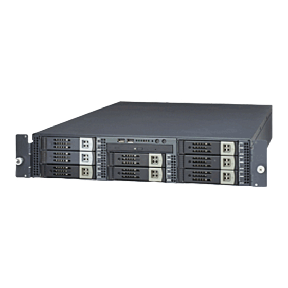
Chapter 1: Overview About the Transport TA26 (B2882) Congratulations on your purchase of the TA26 (B2882), rack mountable, barebone system for the AMD Opteron proces- sor. The TA26 uses AMD's revolutionary x86-64 Opteron™ processor technology, offering exceptional computing power and simultaneous support of 32-bit and 64-bit applications. Removable SCSI hard disk drives provide maximum flexibility and combine with gigabit Ethernet ports to provide powerful computing capacity and optimal I/O bandwidth for the most... -
Page 10: Features
Ultra 320 SCSI controller with ZCR support Processors Motherboard • Dual PGA 940-pin ZIF sockets • Tyan Thunder K8S Pro S2882G3NR motherboard ® • Support for single or dual AMD • eATX form factor (13x12 inches) Opteron™ 200 series processors... -
Page 11: Unpacking
1.3.1 Box contents Component Description Industry standard 2U chassis with eight drive bays. Tyan S2882UG3NR motherboard (pre- installed) 24x slim CD-ROM (pre-installed) SCSI backplane (pre-installed) LED control board (pre-installed) Riser card assembly EPS 12V 2U 460W power supply (pre- installed) or optional 460W 1+1 redun- dant power supply. -
Page 12: Accessories
1.3 Unpacking 1.3.2 Accessories FDD cables and bracket Rail for rack mounting Mounting ears Driver CD and diskettes 2U Server Platform High Performance Motherboard S2882 B2882 Transport TA26 K8S Pro AJS #D 1528 - 100 ID : 1540 - 100 Revision 1.0 Revision 1.0 Hardware... -
Page 13: Opening The Box
1.3 Unpacking 1.3.3 Opening the box Open the box carefully and ensure that all components are present and undamaged. The product should arrive pack- aged as illustrated below. Packaged box contents High Performance Motherboard S2882 Thunder K8S PRO #D 1528 - 100 Revision 1.0 User's Manual Accessory pack... -
Page 14: About The Product
1.4 About the product About the product This section contains hardware diagrams and a block dia- gram of the TA26 system. 1.4.1 System front view and front panel See the diagram below for details of the front panel indicators and switches. Lan activity activity Power... -
Page 15: System Internal View
1.4 About the product 1.4.3 System internal view LED control board PCI riser card assembly CD-ROM drive EPS 12V 460W power supply FDD/HDD bay Processor sockets System fans Power connector Memory slots SCSI backplane Chapter 1: Overview... -
Page 16: Block Diagram
1.4 About the product 1.4.4 Block diagram 184 pin 184 pin 184 pin 184 pin LINK 0B DIMM0 DIMM1 DIMM2 DIMM3 16x16 Hyper Transport@1600MT/s 200-333MT/s Opteron Opteron Processor Processor 144-Bit SO-DIMM144 (ZCR) Adaptec 200-333MHz 144-Bit AIC-7902 SCSI 16x16 Hyper Transport@1600MT/s AMD Chipset LINK 0A PCI-X Slots... -
Page 17: Chapter 2: Setting Up
Chapter 2: Setting up Before you begin This chapter explains how to install motherboard components including CPUs, memory modules, and PCI cards. There are also instructions in this section for installing SCSI hard drives. Careful attention should be given to the precautions men- tioned in this section when setting up your system. -
Page 18: Precautions
2.1 Before you begin 2.1.3 Precautions Components and electronic circuit boards can be damaged by static electricity. Working on a system that is connected to a power supply can be extremely dangerous. Follow the guidelines below to avoid damage to the Transport TA26 or injury to yourself. -
Page 19: Installing Motherboard Components
2.2 Installing motherboard components Installing motherboard components This section describes how to install CPUs, memory mod- ules, and PCI cards. 2.2.1 Removing the chassis cover Follow these instructions to remove the TA26 chassis cover. This step is required before any other procedures in this chapter can be undertaken. -
Page 20: Installing Cpus And Heatsinks
2.2 Installing motherboard components Refitting the chassis cover is a reverse of the removal pro- cess. Place the lid on the chassis and push it forward into place before tightening the screw on the rear of the unit. 2.2.2 Installing CPUs and heatsinks This section describes how to install AMD Opteron proces- sors and heatsinks in your TA26 system. - Page 21 2.2 Installing motherboard components 4. Lift the locking lever on the CPU socket to the upright position. 5. Place the CPU in the socket as shown, making sure that pin 1 is located correctly. Pin 1 Chapter 2: Setting up...
- Page 22 2.2 Installing motherboard components 6. Push the CPU locking lever down to lock the CPU in place. 7. Apply some thermal grease to the top of the CPU and place a heatsink on top as shown. 8. Fix the heatsink in the heatsink retainer as shown and secure with the locking lever.
-
Page 23: Installing Memory
2.2 Installing motherboard components 2.2.3 Installing memory Follow the instructions in this section to install memory mod- ules in your TA26 system. 1. Remove the chassis cover. See Removing the chassis cover on page 11. 2. Locate the memory sockets on the motherboard. Memory sockets 3. -
Page 24: Installing A Pci Card
2.2 Installing motherboard components Note: Memory modules will fit in the slot only one way. Ensure that the notches in the memory modules line up with the corre- sponding bumps in the socket. The locking levers will return to the locked position. Make sure that the memory module is firmly in place. - Page 25 2.2 Installing motherboard components 3. Lift the riser card assembly from the chassis using the green handle as shown. 4. Remove a blanking plate from the riser card assembly as shown. 5. Insert the PCI card into a spare PCI slot in the riser card. Note: Jumpers J24 and J39 must be set correctly when installing PCI-X cards.
- Page 26 2.2 Installing motherboard components 6. Secure the PCI card with the screw you removed with the blanking plate. 7. Replace the riser card assembly in the chassis and push down the green handle as shown. 8. Secure the riser card assembly to the chassis with three screws.
-
Page 27: Installing A Scsi Hard Drive
2.3 Installing a SCSI hard drive Installing a SCSI hard drive The TA26 supports eight, hot-swappable SCSI hard drives. Follow these instructions to install a SCSI hard drive in your TA26 system. 1. Remove a drive tray from the front of the TA26 using the release mechanism as shown. -
Page 28: Installing A Floppy Disk Drive
2.4 Installing a floppy disk drive 4. Slide the drive tray back into the drive bay and push down the locking lever as shown. Note: The TA26 is shipped with SCSI backplane and cables pre-installed. Installing a floppy disk drive This sections describes how to install a floppy disk drive in the TA26 if required. - Page 29 2.4 Installing a floppy disk drive 2. Attach the supplied FDD rails to the floppy disk drive. The wide end of the rails should be towards the front. Note: The FDD rails each have a flat side which should be against the body of the floppy drive when installed.
- Page 30 2.4 Installing a floppy disk drive 4. Slide the floppy disk drive into the drive bay until it clicks into place and fits flush with the front panel. 5. Plug the other end of the supplied floppy disk drive cable into the floppy disk drive controller on the motherboard.
-
Page 31: Rack Mounting
2.5 Rack mounting Rack mounting Follow these instructions to mount the TA26 into an industry standard 19-inch rack. Note: Before mounting the TA26 in a rack, ensure that all internal components have been installed and that the unit has been fully tested. - Page 32 2.5 Rack mounting 3. Slide the remaining sliding rail elements into place on each side of the chassis. The rails should be in the short- est position. 4. Fix the four mounting brackets into the rack as shown. 5. Lift the TA26 and slide it into the rack. Slide it into position between the brackets.
-
Page 33: Chapter 3: Replacing Pre-Installed Components
Chapter 3: Replacing pre-installed components Introduction This chapter describes how to replace all the pre-installed components of your TA26, including PCI card, riser card, motherboard, CD-ROM drive, floppy disk drive, and LED con- trol board. There is also a section covering the replacement of the SCSI backplane. - Page 34 3.2 Replacing motherboard components IDE cable (CD-ROM) USB1 (Bottom) LAN3 (Top)Optional KB(Bottom) Mouse(Top) LAN1/2 J56 (VGA) J57 (COM1) LAN1 LAN2 USB1 KB-MS (Optional) RAGE XL FAN 2 LAN3 CPU2_FAN CH-A FAN 1 KEYLOCK PCI5 BIOS SATA1 SATA2 PCI4 PCI3 PCI2 PCI1 CPU2 SATA3...
- Page 35 3.2 Replacing motherboard components CPU fan power cables Various pin headers exist on your motherboard for cooling fans. See Pin header diagram on page 48. Note: Chassis fans should be connected to the auto fan speed control pin headers on the motherboard.
- Page 36 3.2 Replacing motherboard components USB cables USB1 (Bottom) LAN3 (Top)Optional KB(Bottom) Mouse(Top) LAN1/2 J56 (VGA) J57 (COM1) LAN1 LAN2 USB1 KB-MS (Optional) RAGE XL FAN 2 LAN3 CPU2_FAN CH-A FAN 1 KEYLOCK PCI5 BIOS SATA1 SATA2 PCI4 PCI3 PCI2 PCI1 CPU2 SATA3 CH-B...
- Page 37 3.2 Replacing motherboard components LED Control board connector pin out Function Function 18 17 Speaker/buzzer- Buzzer+ IRTX None Speaker+ IRRX +5 V Reset switch+ PWR+ Power LED- HDD LED- Power LED+ HDD LED + Chapter 3: Replacing pre-installed components...
-
Page 38: Replacing The Motherboard
3.2 Replacing motherboard components 3.2.2 Replacing the motherboard Follow these instructions to replace the motherboard from your TA26. 1. Remove the chassis cover. See Removing the chassis cover on page 11. 2. Remove all cables to the motherboard. See Disconnect- ing all motherboard cables on page 25. -
Page 39: Replacing The Slim Cd-Rom Drive
3.3 Replacing the slim CD-ROM drive Replacing the slim CD-ROM drive This section describes how to remove and replace the CD- ROM drive in your TA26 system. 1. Remove the chassis cover. See Removing the chassis cover on page 11. 2. -
Page 40: Replacing The Led Control Board
3.4 Replacing the LED control board 4. Press the release clip (A) while sliding the CD-ROM drive forward and out of the housing. Replacing the LED control board Follow these instructions to replace the LED control board. 1. Remove the chassis cover. See Removing the chassis cover on page 11. - Page 41 3.4 Replacing the LED control board 3. Remove the cable from the LED control board. LED control board cable 4. Remove the three screws that secure the LED control board to the LED control board bracket and remove it. 5. Position the replacement board in place on the LED con- trol board bracket and secure with three screws.
-
Page 42: Replacing The Usb Board
3.5 Replacing the USB board. Replacing the USB board. Follow these instructions to replace the USB board 1. Remove the chassis cover. See Removing the chassis cover on page 11. 2. Remove the screw that secures the LED board bracket to the chassis (A), push the bracket back (B), and lift it clear of the CD-ROM drive (C). -
Page 43: Replacing The Scsi Backplane
3.6 Replacing the SCSI backplane 4. Remove the screws that secure the USB board to the LED control board bracket and remove it. 5. Position a replacement board on the LED control board bracket and secure with screws. 6. Replace the USB board cable. Replacing the SCSI backplane This section describes how to replace the SCSI backplane on your TA26. - Page 44 3.6 Replacing the SCSI backplane 4. Loosen all the screws securing the green retention clips in place. 5. Turn the green retaining clips so that they don’t hold the backplane in place. 6. Loosen the ten screws that secure the SCSI backplane to the chassis.
- Page 45 3.6 Replacing the SCSI backplane 7. Lift the SCSI backplane from the chassis. Chapter 3: Replacing pre-installed components...
-
Page 46: Scsi Backplane Features
3.6 Replacing the SCSI backplane 3.6.1 SCSI backplane features J1 68PIN SCSI J15 USB OUT JP2 SYSTEM JP1 12C OUT JF1 3 PIN JP7 POWER 4P J16 CD-ROM J18 68 PIN SCSI J2 68 PIN SCSI U21 8051 BZ1 BUZZER F3 3 PIN DS1 FUNCTION J12 BIG 4P... -
Page 47: Scsi Backplane Specifications And Settings
3.6 Replacing the SCSI backplane 3.6.2 SCSI backplane specifications and settings • Raid Back-plane, switch board and USB board Specification: • Support SCSI interface: Ultra 320/160 backward compatibility. • Support hard disk drive 80pin SCA2 Ultra 320/160 backward compati- bility. •... - Page 48 3.6 Replacing the SCSI backplane JP3 display board pin output LAN1 YL LED+ LAN1-LED - LAN1 GR-LED + LAN1-LED - LAN2 YL LED+ LAN2-LED - LAN2 GR-LED + LAN2-LED - LAN3 YL LED+ LAN3-LED - LAN3 GR-LED + LAN3-LED - T-FAIL-LED - Local HDD LED + Local HDD LED -...
- Page 49 3.6 Replacing the SCSI backplane F1, F2, F3fan pin out Sensor J11, J12, J13 power big 4P pin out J14, J15 USB pin out definition definition USB1 POWER USB2 POWER USB1 DATA - USB2 DATA - USB1 DATA + USB2 DATA + USB1 GND USB2 GND KEY PIN...
- Page 50 3.6 Replacing the SCSI backplane JP5 display board pin out HDD POWER LED1 + GND(HDD POWER LED1 -) HDD ACCESS LED1 + HDD FAIL LED1 - HDD POWER LED2 + GND(HDD POWER LED2 -) HDD ACCESS LED2 + HDD FAIL LED2 - HDD POWER LED3 + GND(HDD POWER LED3 -) HDD ACCESS LED3 +...
- Page 51 3.6 Replacing the SCSI backplane Switch board JB1 pin out LAN1 GR-LED + LAN1-LED - LAN1 GR-LED + LAN1-LED - LAN2 GR-LED + LAN2-LED - LAN2 GR-LED + LAN2-LED - LAN3 GR-LED + LAN3-LED - LAN3 GR-LED + LAN3-LED - T-FAIL-LED - Local HDD led + Local HDD led -...
-
Page 52: Replacing The Power Supply
3.7 Replacing the power supply Replacing the power supply Follow these instructions to replace the power supply in your TA26 system. 3.7.1 Standard power supply 1. Remove the chassis cover. See Removing the chassis cover on page 11. 2. Remove all the power cables from the motherboard. See Disconnecting all motherboard cables on page 25. -
Page 53: Optional 1+1 Redundant Power Supply
3.7 Replacing the power supply 3.7.2 Optional 1+1 redundant power supply If the optional 1+1 redundant power supply is fitted, either of the two units can be hot swapped. Follow these instructions to replace a redundant power supply unit. 1. Remove the power cable from the power supply unit you that you want to swap out. - Page 54 3.7 Replacing the power supply 3. Remove the power cables from the motherboard. 4. Remove the two screws at the rear of the power supply housing that secure it to the chassis. 5. Remove the power supply housing as shown. Chapter 3: Replacing pre-installed components...
-
Page 55: Replacing The Cooling Fans
3.8 Replacing the cooling fans Replacing the cooling fans Follow these instructions to replace the chassis cooling fans in your TA26 system. 1. Remove the chassis cover. See Removing the chassis cover on page 11. 2. Locate the fan that you want to replace and unplug the power cable for that fan from the motherboard. -
Page 56: Pin Header Diagram
3.8 Replacing the cooling fans 3.8.1 Pin header diagram The diagram below shows the motherboard pin headers that supply power for the cooling fans. CPU2 FAN 2 FAN 1 USB1 (Bottom) LAN3 (Top)Optional KB(Bottom) Mouse(Top) LAN1/2 J56 (VGA) J57 (COM1) LAN1 LAN2 USB1... -
Page 57: Appendix
BIOS Introduction Your Transport TA26 (B2882) system includes a powerful TYAN Thunder K8S S2882G3NR motherboard with AMI BIOS v8.0 on 4 MB flash ROM. The BIOS is the motherboard’s basic input/output system. The BIOS contains all the settings required to control the key- board, display, disk drives, serial communications, and a number of miscellaneous functions. - Page 58 BIOS setup utility Main Advanced PCI/PnP Boot Security Chipset Power Exit System Overview Use [Enter], [TAB] or AMIBIOS [SHIFT_TAB] to select Version :08.00.xx a field Build Date :7/17/2003 :0AAAA000 Use [+] or [-] to config- ure system time. Processor Type :AMD Opteron™...
-
Page 59: Bios Menu Bar
BIOS menu bar The menu bar at the top of the window lists the following selections: Main To configure basic system setups Advanced Configure advanced chipset options PCI/PnP Configure legacy PnP or PCI settings Boot Configure system boot order Security Configure user and supervisor passwords Chipset Configure chipset management features... -
Page 60: Bios Main Menu
BIOS main menu The Main BIOS menu is the first screen that appears when you enter BIOS setup. The menu has two main frames. The left frame displays all the options that can be configured. "Grayed-out" options cannot be configured, options in blue can be changed. -
Page 61: Bios Advanced Menu
BIOS advanced menu Select any of the items in the left frame of the screen, such as Super I/O Configuration, to go to the submenu for that item. You can display an Advanced BIOS Setup option by high- lighting it using the <Arrow> keys. All Advanced BIOS Setup options are described in this section. -
Page 62: Ide Configuration Submenu
Features Description USB Configuration Configures USB controller and legacy device support Device and PCI Slots Config- Allows control of integrated devices and uration cards plugged into PCI slots. Hardware Health Configura- Configures and views hardware monitor tion IDE configuration submenu You can use this screen to change IDE configuration settings. -
Page 63: Floppy Configuration Submenu
Feature Option Description • Auto Primary/Sec- Auto - IDE drive type set by sys- • User ondary Master tem BIOS • ATAPI Removable Primary/Sec- User - IDE drive type set by • CD-ROM ondary Slave user • None ATAPI Removable - Read/write media (e.g. -
Page 64: Super I/O Configuration Submenu
Features Option Description Floppy Configuration • Disabled Floppy A This setting defines the type of • 360 KB 5 1/4” floppy drive installed in the sys- • 1.2 MB 5 1/4” • 720 KB 3 1/2” • 1.44 MB 3 1/2” •... - Page 65 Feature Option Description Win627 Super I/O Chipset • Enabled Onboard Enables or disables the onboard floppy • Disabled floppy con- controller troller • 3F8/IRQ4 Serial Port 1 Sets the serial port 1 (com 1) base I/O • 3E8/IRQ4 Address address and an interrupt number. Dis- •...
-
Page 66: Hardware Health Event Monitoring Submenu
Hardware health event monitoring submenu You can use this screen to view the hardware health configu- ration Settings. The settings are described on the following pages. Main Advanced PCI/PnP Boot Security Chipset Power Exit Hardware health Event Monitoring Use [Enter], [TAB] or [SHIFT_TAB] to select DIMM 2,5V VRM Temperature :xx C/ xxx F... -
Page 67: Motherboard Voltages Report Submenu
Feature Option Description CPU1 Fan Speed — Displays speed of fans con- nected to appropriate fan CPU2 Fan Speed headers. FAN1 Speed FAN2 Speed FAN3 Speed FAN4 Speed FAN5 Speed Motherboard Voltages Report — Displays voltage for CPU, memory and other devices. Auto FAN 1, 2, 3 Power Con- Disabled FAN power duty cycle is... -
Page 68: Acpi Settings Submenu
ACPI settings submenu Use this screen to change options for ACPI. A description of the selected item appears on the right side of the screen. Main Advanced PCI/PnP Boot Security Chipset Power Exit ACPI Settings Use [Enter], [TAB] or ACPI Aware O/S [Yes] [SHIFT_TAB] to select a field... -
Page 69: Advanced Acpi Configuration Submenu
Advanced ACPI configuration submenu Use this screen to select options for ACPI. A description of the selected item appears on the right side of the screen. Main Advanced PCI/PnP Boot Security Chipset Power Exit Advanced ACPI Configuration Use [Enter], [TAB] or [SHIFT_TAB] to select ACPI 2.0 Support [No]... -
Page 70: Event Logging Details Submenu
Event logging details submenu You can use this screen to view the event log control menu. This logs system events (such as CMOS clear, ECC memory errors, etc.) and writes the log into NVRAM. The settings are described on the following pages. Main Advanced PCI/PnP Boot Security Chipset Power Exit DMI Event Logging Use [Enter], [TAB] or... -
Page 71: Hyper Transport Configuration Submenu
Hyper transport configuration submenu Use this screen to view the hyper transport configuration Menu and make changes. Main Advanced PCI/PnP Boot Security Chipset Power Exit Hyper Transport Configuration Use [Enter], [TAB] or [SHIFT_TAB] to select CPU1: CPU2 HT Link Speed [Auto] a field CPU1: CPU2 HT Link Width... -
Page 72: Device And Pci Slots Configuration Submenu
Feature Option Description • Auto CPU1: PCI-X0 Specifies CPU1 to PCI X Hyper Trans- • 2 Bit HT Link Width port Link Data width. • 4 Bit • 8 Bit • 16 Bit Device and PCI slots configuration submenu Use this screen to view the Device & PCI Slot Configuration Menu. - Page 73 Onboard serial ATA Allows user to select mode for • RAID mode serial ATA. Check Web site for serial ATA RAID support: http://www.tyan.com • Enabled Gigabit LAN option Allows user to enable or disable • Disabled onboard gigabit LAN controller...
-
Page 74: Remote Access Configuration Submenu
Remote access configuration submenu Use this screen to view the remote access configuration menu. This feature allows remote access to the Server using the serial port. Main Advanced PCI/PnP Boot Security Chipset Power Exit Configure Remote Access Type and Parameters Use [Enter], [TAB] or [SHIFT_TAB] to select Remote Access... -
Page 75: Usb Configuration Submenu
Feature Option Description • Disabled Redirec- Disabled - Turns off the redirection after • Boot Loader tion after POST. • Always BIOS Boot Loader - Redirection is active dur- POST ing POST and during Boot Loader. Always - Redirection is always active. (Some OSs may not work if set to always). -
Page 76: Advanced Pci/Pnp Menu
Advanced PCI/PnP menu Use this screen to view PnP (Plug & Play) BIOS Configura- tion Menu. This menu allows the user to configure how the BIOS assigns resources & resolves conflicts. Main Advanced PCI/PnP Boot Security Chipset Power Exit Advanced PCI/PnP Settings Use [Enter], [TAB] or WARNING: Setting wrong values in below sec- [SHIFT_TAB] to select... - Page 77 Feature Option Description PCI Latency Timer 32, 64, 96 Controls how many PCI clocks ...248 cycles each PCI device can hold the bus for. Higher values allow all devices longer bus access time, thus improving PCI bandwidth. • Ascent PC Bus Scan Order Ascent - Scan PCI bus from 0-max •...
-
Page 78: Bios Boot Settings Menu
BIOS boot settings menu Display the boot settings option by highlighting it using the <Arrow> keys and pressing <Enter>. Main Advanced PCI/PnP Boot Security Chipset Power Exit Boot Settings Use [Enter], [TAB] or Boot Settings Configuration [SHIFT_TAB] to select a field Boot Device Priority Hard Disk Drives Use [+] or [-] to config-... - Page 79 Feature Option Description Boot Settings Configuration • Enabled Quick Boot Mode Allows user bypass BIOS self • Disabled test during POST. • Disabled Quiet Boot Enable this option to hide BIOS • Enabled Post messages during POST • Force BIOS Add On ROM Dis- Allows user to force BIOS/Option •...
-
Page 80: Boot Device Priority Submenu
Boot device priority submenu Use this screen to select options for the boot device priority. Main Advanced PCI/PnP Boot Security Chipset Power Exit Boot Device Priority Use [Enter], [TAB] or 1st Boot Device [1st FLOPPY DRIVE] [SHIFT_TAB] to select a field Use [+] or [-] to config- ure system time. -
Page 81: Hard Disk Submenu
Hard disk submenu Use this screen to select options for the hard disk drives. Main Advanced PCI/PnP Boot Security Chipset Power Exit Hard Disk Drives Use [Enter], [TAB] or 1st Drive [xx,xxx-xxxxx:xxx] [SHIFT_TAB] to select a field Use [+] or [-] to config- ure system time. -
Page 82: Removable Drives Submenu
Removable drives submenu Use this screen to select options for the removable drives. Main Advanced PCI/PnP Boot Security Chipset Power Exit Removable Drives Use [Enter], [TAB] or 1st Drive [1st FLOPPY DRIVE] [SHIFT_TAB] to select a field Use [+] or [-] to config- ure system time. -
Page 83: Atapi Cd-Rom Drives Submenu
ATAPI CD-ROM drives submenu Use this screen to select options for the ATAPI CD-ROM drives. Main Advanced PCI/PnP Boot Security Chipset Power Exit ATAPI CD-ROM Drives Use [Enter], [TAB] or 1st Drive [xx,xxx-xxxxx:xxx] [SHIFT_TAB] to select a field Use [+] or [-] to config- ure system time. -
Page 84: Bios Security Menu
BIOS security menu The system can be configured so that all users must enter a password every time the system boots or when BIOS Setup is entered, using either the Supervisor password or User password. The Supervisor and User passwords activate two different levels of password security. -
Page 85: Bios Chipset Settings
Feature Option Description Change Select this option to change User Pass- User — word Password Clear User — Select this option to clear User Password Password Boot Sec- Disabled Protects the first sector of the Hard Drive tor Virus Enabled from being written Protection BIOS chipset settings... -
Page 86: Northbridge Chipset Configuration Submenu
Northbridge chipset configuration submenu This menu gives options for the Northbridge chipset configu- ration settings. Select a menu by highlighting it using the <Arrow> keys and pressing <Enter>. Main Advanced PCI/PnP Boot Security Chipset Power Exit Northbridge Bridge Chipset Configuration Use [Enter], [TAB] or [SHIFT_TAB] to select Memory Configuration... -
Page 87: Ecc Configuration Submenu
Feature Option Description Memory configuration • Disabled Bank Interleaving Allows memory access to be spread • Auto across memory banks. • Disabled Node Interleaving Allows memory access to be spread • Auto across memory nodes. • 8 beats Burst length Burst length must be set to 8 beats •... - Page 88 Feature Option Description • Disabled DRAM BG DRAM scrubbing corrects and rewrites • 40 ns Scrub memory errors allowing later reads to be • 80 ns corrected. Doing this while memory is • 160 ns not being used improves performance. •...
-
Page 89: Southbridge Chipset Configuration Submenu
Feature Option Description • Disabled Data Cache BG Allows the L1 Data Cache RAM to be • 40ns Scrub corrected while idle. • 80ns • 160ns • 320ns • 640ns • 1.28us • 2.56us • 5.12us • 10.2us • 20.5us •... -
Page 90: Pci-X Chipset Configuration Submenu
Feature Option Description Southbridge chipset configuration • Enabled 2.0 SM Bus Enables or disables the SM bus 2.0 • Disabled Controller controller in the AMD8111 I/O hub. • Auto HT Link 0 P- Auto uses hardware compensation • Data Comp Mode values. - Page 91 Feature Option Description PCI-X chipset configuration • Auto HT Link 0 P- Auto uses hardware compensa- • Data Comp Mode tion values. Other values add to • CalComp+Data or subtract from hardware gener- • CalComp-Data ated value. Recommended set- ting is Auto. •...
-
Page 92: Bios Power Menu
BIOS power menu This menu enables the user to configure power management settings. Main Advanced PCI/PnP Boot Security Chipset Power Exit PCI-X Chipset Configuration Use [Enter], [TAB] or [SHIFT_TAB] to select Power Management [Enabled] a field Use [+] or [-] to config- Resume On Ring [Disabled] ure system time. -
Page 93: Bios Exit Menu
Feature Option Description • Power On Restore on Configures how the system board • Power Off AC/Power Loss responds to a power failure. • Last State BIOS exit menu Display an exit BIOS setup option by highlighting it with the <Arrow>... -
Page 94: Technical Support
Help resources: 1. See the beep codes section in the motherboard manual 2. See the TYAN Web site for FAQs, bulletins, driver updates and other information: http://www.tyan.com 3. Only contact TYAN after first speaking with your dealer 4. Check the TYAN user group: alt.comp.periphs.mainboard.TYAN...
Need help?
Do you have a question about the Transport TA26 B2882 and is the answer not in the manual?
Questions and answers