Table of Contents
Advertisement
Quick Links
Advertisement
Table of Contents

Related Manuals for TYAN B7086T70BV12HR


Summary of Contents for TYAN B7086T70BV12HR
- Page 1 TN70B-B7086 Service Engineer’s Manual http://www.tyan.com...
- Page 2 Neither this manual, nor any material contained herein, may be reproduced without written consent of manufacturer. ® Copyright 2016 MiTAC International Corporation. All rights reserved. TYAN is a registered trademark of MiTAC International Corporation. Version 1.0...
- Page 3 There will be danger of explosion if battery is incorrectly replaced. Replace only with the same or equivalent type recommended by manufacturer. Dispose of used battery according to manufacturer instructions and in accordance with your local regulations. http://www.tyan.com...
-
Page 4: About This Manual
About this Manual This manual is intended for trained service technician/personnel with hardware knowledge of personal computers. It is aimed to provide you with instructions on installing your TYAN TN70B-B7086 How this guide is organized This guide contains the following parts:... -
Page 5: Safety And Compliance Information
Safety and Compliance Information Before installing and using TYAN TN70B-B7086, take note of the following precautions: ·Read all instructions carefully. ·Do not place the unit on an unstable surface, cart, or stand. ·Do not block the slots and opening on the unit, which are provided for ventilation. -
Page 6: Safety Information
You must become familiar with the safety information in this guide before you install, operate, or service TYAN products. Symbols on Equipment Caution. This symbol indicates a potential hazard. -
Page 7: General Precautions
· Do not attempt to move a fully loaded rack. Remove equipment from the rack before moving it. · Do not attempt to move a rack on an incline that is greater than 10 degrees from the horizontal. · Make sure the rack is properly secured to the floor or ceiling. http://www.tyan.com... - Page 8 This will reduce the risk of personal injury, fire, or damage to the equipment. The total rack load should not exceed 80 percent of the branch circuit rating. Consult the electrical authority having jurisdiction over your facility wiring and installation requirements. http://www.tyan.com...
- Page 9 Replace the battery only with a spare designated for your product. · Do not attempt to recharge the battery. · Dispose of used batteries according to the instructions of the manufacturer. Do not dispose of batteries with the general household waste. To forward http://www.tyan.com...
- Page 10 TYAN, your authorized TYAN partner, or their agents. Equipment Modifications · Do not make mechanical modifications to the system. TYAN is not responsible for the regulatory compliance of TYAN equipment that has been modified.
-
Page 11: Table Of Contents
Table of Contents Chapter 1: Overview ................ 13 ® About the TYAN TN70B-B7086 ..........13 Product SKUs ................. 13 Features.................. 14 Standard Parts List ..............19 1.4.1 Box Contents and Accessories ........19 About the Product ..............20 1.5.1 System Front View ............20 1.5.2... - Page 12 Security ................. 143 Boot ..................148 Save & Exit ................150 Appendix I: Cable Connection Tables ......... 152 Appendix II: FRU Parts Table ............154 Appendix III: Fan and Temp Sensors ........... 156 Appendix IV: Technical Support ........... 160 http://www.tyan.com...
-
Page 13: Chapter 1: Overview
TYAN also offers the TN70B-B7086 in a version that can support up to (12) 2.5” or 3.5” hot-swap hard drives. The TN70B-B7086 uses TYAN‟s latest chassis featuring a robust structure and a solid mechanical enclosure. All of this provides TN70B-B7086 the power and flexibility to meet the needs of nowadays server application. -
Page 14: Features
Features TYAN TN70BB7086 (B7086T70BV8E4HR) Form Factor 2U Rackmount Gross Weight 25 kg Chassis Model TN70B System Dimension (D x W x H) 27.56" x 17.72" x 3.43" (700 x 450 x 87mm) Motherboard S7086GM3NRE Board Dimension EATX, 12"x13" (305x330mm) Buttons... - Page 15 (1) OCP slot for Mezz Card/ (1) Proprietary slot Expansion Slots Note: for SAS Mezz Card/ (2) PCI-E Gen3 x4 MiniSAS HD for NVMe devices(TYAN Proprietary) M7056-L24-3F / M7056-R24-3F / M2092, 2U Pre-install TYAN Riser Riser Card, (2) mini-SAS HD connectors, PCI-E...
- Page 16 RoHS 6/6 Compliant Barebone (1) TN70B-B7086 Barebone Package (1) Web User's manual / (1) Quick Installation Manual Contains Guide Installation CD (1) TYAN installation CD TYAN TN70BB7086 (B7086T70BV12HR) Form Factor 2U Rackmount Gross Weight 25 kg Chassis Model TN70B System Dimension (D x W x H) 27.56"...
- Page 17 (1) PCI-E Gen3 x16 slot (w/x16/8 link)+(1) PCI-E Gen3 x8 slot (w/x0/8 link)+(1) PCI-E Gen3 x8 slot Expansion Slots (1) OCP slot for Mezz Card/ (1) Proprietary slot Note: for SAS Mezz Card Pre-install TYAN Riser M7056-L24-3F / M7056-R24-3F Card Port Q'ty (3) GbE ports Controller...
- Page 18 Non-operating Temp. - 40° C ~ 70° C (-40° F ~ 158° F) Environment In/Non-operating 90%, non-condensing at 35° C Humidity RoHS RoHS 6/6 Compliant Barebone (1) TN70B-B7086 Barebone Package (1) Web User's manual / (1) Quick Installation Manual Contains Guide Installation CD (1) TYAN installation CD http://www.tyan.com...
-
Page 19: Standard Parts List
TYAN‟s website for service: http://www.tyan.com Box Content (1) 2U chassis with(12)hot swap 2.5”/3.5” HDD bays/B7086T70BV8E4HR SKU (1) 2U chassis with(12)hot swap 2.5”/3.5” HDD bays/B7086T70BV12HR SKU (1) (1+1) redundant, 770W DELTA DPS-770GB C Power Supply (pre-installed) (1) S7086 system board (pre-installed) ... -
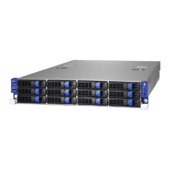
Page 20: About The Product
About the Product The following views show you the product. 1.5.1 System Front View B7086T70BV12HR Power On/OFF Button with Power On/Off LED IPMI LED ID LED RESET Button ID Button USB Ports 3.5” /2.5” HDD bays http://www.tyan.com... - Page 21 2 PSU and 2 PSU AC cords are Amber solid on connected. After system is powered on, disconnect 1 PSU AC cord. 2 PSU and 2 PSU AC cords are Amber solid on connected. After system is powered on, disconnect 1 PSU. http://www.tyan.com...
- Page 22 Color: Red No Driver Present or power disconnected No Activity Solid ON Driver Present Access Activity Blinking HDD Drive Fail Don‟t care Solid ON RAID Rebuild Don‟t care Blinking @ 4Hz HDD Drive Locate Identifier Don‟t care Blinking @ 1Hz http://www.tyan.com...
-
Page 23: System Rear View
10 Mbps Blinking Green Active Solid Green Solid Green Link 100 Mbps Blinking Green Solid Green Active Solid Green Solid Yellow Link 1000 Mbps Blinking Green Solid Yellow (1Gbps) Active NOTE: “Left” and “Right” are viewed from the rear panel. http://www.tyan.com... - Page 24 I210 LAN chip is support on LAN3 can up to 1Gbps. Peripheral devices can be plugged straight into any of these ports but software may be required to complete the installation. ID LED Status LED Color Behavior Remark Normal ID LED Blue Local and remote Located Solid on http://www.tyan.com...
-
Page 25: Motherboard (S7086) Layout
The board you receive may not look exactly like the above diagram. The DIMM slot numbers shown above can be used as a reference when reviewing the DIMM population guidelines shown later in the manual. For the latest board revision, please visit our web site at http://www.tyan.com. http://www.tyan.com... -
Page 26: Jumpers & Connectors
8. LAN Port#2(LAN2) 25.USB 2.0 Header(USB2_HD1) 9. ID LED 26.PSMI Connector(PSMI_HD1) 10. 4-pin Fan Connector(SYS_FAN5) 27. 24-pin Power Connector(PW1) 11. TYAN Module Header 28. USB 3.0 Header(USB3_HD1) 12. BMC LED 29. TYPE_A USB Header(TYPEA_USB3) 13. COM Port(COM2) 30. 4-in-1 Mini SAS Connector(SSATA0-3) 14. -
Page 27: Block Diagram (S7086)
1.5.5 Block Diagram (S7086) http://www.tyan.com... -
Page 28: Internal View
(12) hotswap 3.5”/2.5” HDD trays (underneath) SATA/SAS HDD Backplane Board (can be install 12 facilities) Power Distribution Board System Fan Module (pre-install 4 Fans) Internal 2.5” HDD trays (can be install 2 facilities) PCI-E Riser Card Bracket System Power Supply (underneath) http://www.tyan.com... - Page 29 (12) hotswap 3.5”/2.5” HDD tray (underneath) SATA/SAS HDD backplane (can be install 12 facilities) Power Distribution Board System Fan Module (Pre-install 4 fans) Internal 2.5” HDD trays (can be install 2 facilities) CPU Socket & Memory Slots System Power Supply (underneath) http://www.tyan.com...
- Page 30 NOTE http://www.tyan.com...
-
Page 31: Chapter 2: Setting Up
Caution! To avoid damaging the motherboard and associated components, do not use torque force greater than 7kgf/cm (6.09 lb/in) on each mounting screw for motherboard installation. Do not apply power to the board if it has been damaged. http://www.tyan.com... -
Page 32: Precautions
Metallic parts or metal flakes can cause electrical shorts. CAUTION: Please note that the following illustrations may not look exactly like the rackmount server you purchased. Therefore, the illustrations should be held for your reference only. http://www.tyan.com... -
Page 33: Installing Motherboard Components
2.1.1 Removing the Chassis Cover Follow these instructions to remove the TN70B-B7086 chassis cover. Unscrew the rear top cover on the back side. Unscrew the front top cover and pull the latches aside to lift up the top cover. http://www.tyan.com... - Page 34 Slide the rear top cover out. http://www.tyan.com...
-
Page 35: Removing The Riser Card Brackets
2.1.2 Removing the Riser Card Brackets Follow these instructions to remove the PCI-E Riser Card Brackets. Loose three thumb screws to release the PCI-E Riser Card Brackets. Lift up the Riser Card Brackets. http://www.tyan.com... -
Page 36: Installing The Cpu And Heatsink
Locate the CPU sockets. Always start with CPU0 first. Pull the first and second levers slightly away from the socket and then push the second lever to a fully open position. Push the CPU socket cover to a fully open position. Take out the protection cap. http://www.tyan.com... - Page 37 Place the CPU into the socket and make sure that the gold arrow is located in the right direction. Close the CPU socket cover and press the levers down to secure the CPU. http://www.tyan.com...
- Page 38 Position the heatsink on top of the CPU and secure it with 4 screws. 7. Repeat the procedures mentioned earlier to install the second CPU and heatsink. http://www.tyan.com...
-
Page 39: Installing The Memory
Align the memory module with the slot. When inserted properly, the memory slot locking levers lock automatically onto the indentations at the ends of the module. Follow the recommended memory population table to install the other memory modules. http://www.tyan.com... - Page 40 1. √ indicates a populated DIMM slot. 2. Use paired memory installation for max performance. 3. Populate the same DIMM type in each channel, specifically - Use the same DIMM size - Use the same # of ranks per DIMM http://www.tyan.com...
- Page 41 √ √ √ √ √ √ √ CPU1_DIMM_E0 CPU1_DIMM_E1 √ √ √ CPU1_DIMM_F0 √ √ √ √ √ √ √ √ CPU1_DIMM_F1 √ √ √ √ √ √ CPU1_DIMM_G0 CPU1_DIMM_G1 √ √ CPU1_DIMM_H0 √ √ √ √ CPU1_DIMM_H1 √ http://www.tyan.com...
- Page 42 NOTE 1: 1DPC => One dimm per channel NOTE 2: 2DPC => Two dimm per channel NOTE 2: 3DPC => Three dimm per channel Physical Ranks are used to calculate DIMM Capacity. Supported DRAM Densities are 4Gb, 8Gb. http://www.tyan.com...
-
Page 43: Installing Hard Drives
Warning!!! Always install the hard disk drive to the chassis after the chassis is secured on the rack. Press and hold the locking lever latch to pull the locking lever open. Slide the HDD tray out. http://www.tyan.com... - Page 44 Unscrew the drive bracket from the HDD tray. Place a 3.5” hard drive into the drive tray and use 6 screws to secure the HDD. Reinsert the HDD tray into the chassis and press the locking lever to secure the tray. http://www.tyan.com...
- Page 45 Option B: for 2.5” hard drives Place a 2.5” hard drive into the HDD tray and use 4 screws to secure the HDD. Reinsert the HDD tray into the chassis and press the locking lever to secure the tray. http://www.tyan.com...
- Page 46 2 Insert the 2.5” hard drives into the bracket and secure them with eight screws. Connect the SATA signal cables and the HDD power cables. 3 Position the HDD bracket in its original place. Screw it firmly to the chassis. http://www.tyan.com...
-
Page 47: Installing The Pci-E Cards
2.1.6 Installing the PCI-E Cards TN70B-B7086 (B7086T70BV12HR) supports PCI-E Riser Card Brackets. A power cable (2x3p/2x4p) is required for GPU cards. Follow these instructions to install PCI-E cards. Unscrew the PCI-E slot to take out the PCI bracket. Insert the PCI-E card and securely screw as shown. - Page 48 Unscrew the PCI-E slot. Take out the PCI-E to NVME Riser card. M2092 Riser Card Form Factor W68.9xL96.3(mm) Uplink PCI-E G3 x8 interface Integrated I/O Single PCI-E x8 / Dual PCI-E G3 x4 ports Dual NVMe SSD drives http://www.tyan.com...
-
Page 49: Pci-E Riser Cards Specification
When installing X16 Gen3 Device in the PCI-E#2 Slot, PCI-E#1 Slot can‟t be used. When installing X8 Gen3 Device in PCI-E#1 Slot, PCI-E#2 the other X8 Gen3 part can‟t used. http://www.tyan.com... -
Page 50: Rack Mounting
Sliding Rails x 2 Screws Kit x 2 2.2.1 Installing the Server in a Rack Follow these instructions to mount the TYAN TN70B-B7086 into an industry standard 19" rack. NOTE: Before mounting the TYAN TN70B-B7086 in a rack, ensure that all internal components have been installed and that the unit has been fully tested. -
Page 51: Installing The Inner Rails To The Chassis
1. Press the button to pull out the inner rail from the outer rail of the TN70B -B7086 sliding rails. 2. Align the inner sliding rail (1) on the side of the server, and pull towards the arrow (2) to secure the six hooks. http://www.tyan.com... -
Page 52: Installing The Outer Rails To The Rack
(2 in the front and 2 in the rear). 2.2.4 Rack mounting the Server Lift the unit and then insert the inner slide rails into the middle rails. Press the button to push the whole system into the rack. http://www.tyan.com... - Page 53 3. Secure the whole system with 2 (B) screws. 4. Repeat the same procedures in reverse NOTE: To avoid injury, it is strongly recommended that at least two people lift the TYAN TN70B-B7086 to hook on or unhook from the rails. http://www.tyan.com...
-
Page 54: Chapter 3: Replacing Pre-Installed
This chapter explains how to replace the pre-installed components, including the Motherboard, M1701T70-FPB Front Panel Board, M1702T70-USB Board,PCI-E Riser Card, M1275T70B-BP12-12/ M1275T70B-BP12E-12 SAS/SATA HDD Backplane, System Fans and System Power Supply,etc. Disassembly Flowchart The following flowchart outlines the disassembly procedure. http://www.tyan.com... -
Page 55: Removing The Cover
TN70B-B7086 has two pre-installed PCI-E×16 riser cards. Follow the instructions below to disassemble the M7056-L24-3F M7056-R24-3F PCI-E riser cards. 1 Unscrew to take out the PCI-E cards. 2 Unscrew the M7056-R24-3F riser card to replace a new one if necessary. http://www.tyan.com... - Page 56 3 Repeat the same procedures for the second Riser Card Assembly. 4 Unscrew the M7056-L24-3F riser card to replace a new one if necessary. http://www.tyan.com...
-
Page 57: Disconnecting All Motherboard Cables
Disconnecting All Motherboard Cables Before replacing the motherboard or certain components, remove cables connected to the motherboard. Follow these instructions to remove all cables. 1. Disconnect Mini SAS, USB and 2x12pin Cables. 2. Disconnect PSMI and front panel cable. Disconnect power cable. http://www.tyan.com... -
Page 58: Removing The Motherboard
After removing all of the aforementioned cables, follow the instructions below to remove the motherboard from the chassis. Remove the heatsinks and processors if installed. Remove the nine screws securing the motherboard to the chassis. Carefully lift the motherboard from the chassis. http://www.tyan.com... -
Page 59: Replacing The Power Distribution Board
Replacing the Power Distribution Board Follow these instructions to replace the M1601T70-D-PDB power distribution board. 1 Disconnect all the cables. 2 Unscrew to replace a new power distribution board. http://www.tyan.com... -
Page 60: Replacing The Front Panel Board
Replacing the Front Panel Board For B7086T70BV12HR SKU Follow these instructions to replace the M1701T70-FP Front Panel Board. 1 Unscrew to release the Front Panel Board cover. 2 Remove the Front Panel Board cover. http://www.tyan.com... - Page 61 3 Unscrew the Front Panel Board to replace a new one. 4 Disconnect the Front Panel Board to replace a new one. 5 Follow the steps described earlier in reverse to reinstall the Front Panel Board. http://www.tyan.com...
-
Page 62: Front Panel Board Specifications
Power On/Off LED Color: Green (after power on) ID LED Color: Blue LEDs Warning (IPMI) LED Dual Color: Amber (Warning) / Green (Normal) RESET button Push buttons ID button Power On/Off button with Power On/Off LED http://www.tyan.com... -
Page 63: Fpb Led And Connector Pin Definition
Chassis ID LED Locate LED key.* System not identified J1: FPIO connector Definition Definition PW_LED+ +5VSB ID_LED+ PW_LED- ID_LED- HD_LED+ LED_FAULT1- HD_LED- LED_FAULT2- PWR_SW+ LAN_ACT PWR_SW- LAN_LINK# RESET+ SMB_DAT RESET- SMB_CLK ID_SW- Temp_sensor SMB_ALR FPB_HDD_ACTIVITY_G- SMB_CLK FPB_HDD_FAULT_R- SMB_DAT http://www.tyan.com... -
Page 64: Replacing The Usb Board
Replacing the USB Board Follow these instructions to replace the M1702T70-USB Board. 1 Unscrew to release the USB front cover. 2 Remove the USB front cover. http://www.tyan.com... - Page 65 3 Unscrew the USB Board. 4 Disconnect the USB Board to replace a new one. 5 Follow the steps described earlier in reverse to reinstall the USB Board. http://www.tyan.com...
-
Page 66: Usb Board Specifications
USB Board Connector Pin Definition J2: 2x5-pin Connector for FP Connector of Motherboard Definition Description Definition Description VCC_USB USB power VCC_USB USB power USB_P0_N Port1(J1) USB- USB_P1_N Port2(J3) USB- USB_P0_P Port1(J1) USB+ USB_P1_P Port2(J3) USB+ GND1 Ground GND2 Ground No connect http://www.tyan.com... -
Page 67: Replacing The System Fan
Follow these instructions to replace the system fan. 1 Press the latch in the direction as shown to lift up the fan in an iron holder. 2 Take out the fan unit. 3 Loose the screws on both sides. http://www.tyan.com... - Page 68 4 Push the latch in the direction as the arrow shown to release the fan from the iron holder. 5 Remove the iron holder to replace a new fan. 6 After replacing a new one, put the fan unit back into the cage. http://www.tyan.com...
-
Page 69: Replacing The Fan Backplane Board
Replacing the Fan Backplane Board Follow these instructions to replace the M1806G70-FB Fan Board in your system. 1. Disconnect all the fan power cable. Use a screw drive to unscrew the fan cage. http://www.tyan.com... - Page 70 And lift it up from the chassis. Release the 14 screws on the Fan Backplane Board to replace a new one. Follow the steps described in reverse order to reinstall the fan cage. http://www.tyan.com...
-
Page 71: Fan Bp Board Specifications
(2) 1x4pin R/A Power Connector (8) 2x2pin Fan Connectors Integrated I/O (1) 2x10pin Barebone Fan Connector (1) 2x2pin Connector for S7086 3.9.2 Fan BP Board LED Definitions FAN Status Green LED(Right) Red LED(Left) With Fan Without Fan http://www.tyan.com... -
Page 72: Connector Pin Definitions
3.9.3 Connector Pin Definitions Power Connector (PWR1/PWR2) Definition Definition +12V Barebone Fan Connector (J8) Definition Definition FANIN1 FANIN6 FANIN2 FANIN7 FANIN3 FANIN8 FANIN4 SIO_FANIN1 FANIN5 SIO_ FANIN2 MB_PWM2 MB_PWM1 SIO_ FANIN3 SMBUS_3V3_DATA SIO_ FANIN4 SMBUS_3V3_CLK VDD_3.3_AUX MB_PWM3 http://www.tyan.com... -
Page 73: Replacing The Hdd Backplane Board
Fan Module. Disconnect the power cables attached to the HDD BP Board. Unscrew the HDD BP Board. Remove the HDD BP Board from the hook. Replace a new HDD BP Board and reinstall it into the chassis following the steps in reverse. http://www.tyan.com... -
Page 74: Hdd Bp Board Specifications
12-port SAS/SATA 12G (4) MiniSAS SATA/SAS HD connector (SFF-8643) on the backplane (3) MiniSAS SATA/SAS connector Integrated I/O One 2x4 pin power connector Two 2x5 pin JTAG connector 24 LED indicate HDD and RAID status One SATA SGPIO connector(J12) http://www.tyan.com... - Page 75 (4) MiniSAS SATA/SAS HD connector (SFF-8643) on the backplane (3) MiniSAS SATA/SAS connector One 2x4 pin power connector Integrated I/O Two 2x5 pin JTAG connector 24 LED indicate HDD and RAID status One SATA SGPIO connector(J12) 4 NVME Connector(NVME0/1/2/3) http://www.tyan.com...
-
Page 76: Connector Pin Definitions
1. 2x4 pin PWR Connetor(PWR1)Pin Definition Definition Definition +12V +12V +12V +12V 2. SATA SGPIO Header (J12) Pin Definition Definition Definition SLOAD SDATA IN SCLOCK SDATA OUT- P3V3_AUX HD_ERR_LED 2. SATA JTAG Header (J11/J13) Pin Definition Definition Definition TCK_A TDO_A VDD_3P3_RUN TDI_A TMS_A http://www.tyan.com... -
Page 77: Replacing The Power Supply
Press and hold the latch to pull the power supply out. After replacing a new power supply, press and hold the latch to push the power supply back into the chassis. http://www.tyan.com... -
Page 78: Chapter 4: Bios Setup
Select the previous value/setting of the field <+> Select the next value/setting of the field <F8> Load Fail Safe default configuration values of the menu <F3> Load the Optimal default configuration values of the menu <F4> Save and exit <Enter> Execute command or select submenu http://www.tyan.com... -
Page 79: Getting Help
BIOS updates over the product lifespan of the motherboard. The BIOS menus provided are current as of the date when this manual was written. Please visit TYAN‟s website at http://www.tyan.com for information on BIOS updates available for this specific motherboard. -
Page 80: Main Menu
It displays BIOS related information. Memory Information This displays the total memory size. System Date Adjust the system date. MM (Months): DD (Days): YYYY (Years) System Time Adjust the system clock. HH (24 hours format): MM (Minutes): SS (Seconds) Access Level Read only. http://www.tyan.com... -
Page 81: Advanced Menu
ACPI Settings System ACPI Parameters. Hardware Health Configuration Hardware health Configuration Parameters. Onboard Device Configuration Onboard Device Configuration. PCIE Slot Configuration Onboard PCIe Slot Configuration WatchDog Timer Configuration WatchDog Configuration ASPEED Super IO Configuration System Super IO Chip parameters http://www.tyan.com... - Page 82 PCI, PCI-X and PCI Express Settings CSM Configuration CSM Configuration, Enable/Disable Option ROM execution setting,etc Trusted Computing (optional function) Trusted Computing (TPM) settings. NOTE: If no TPM chipset is on, the Trusted Computing submenu will not appear. USB Configuration USB Configuration Parameters. http://www.tyan.com...
- Page 83 ACPI Settings Enable ACPI Auto Configuration Enable or disable BIOS ACPI Auto Configuration. Disabled / Enabled Enable Hibernation Enables or disables System ability to Hibernate (OS/S4 Sleep State). This option may not be effective with some OS. Disabled / Enabled http://www.tyan.com...
- Page 84 4.3.2 Hardware Health Configuration Auto Fan Control Auto Fan Control help. Disabled / Enabled BMC Alert Beep BMC Alert Beep On/Off. On / Off PSU Status Monitor PMBus support Disabled / Enabled http://www.tyan.com...
- Page 85 4.3.2.1 Sensor Data Register Monitoring When you enter the Sensor Data Register Monitoring submenu, you will see the following dialog window pop out. Please wait 8~10 seconds. NOTE 1: SDR can not be modified. Read only. http://www.tyan.com...
- Page 86 http://www.tyan.com...
- Page 87 Enabled/Disabled Load Option ROM for LAN Devices. Enabled with PXE / Disabled Onboard LAN #2 Enable or disable the Onboard Network Controller. Enabled / Disabled Load Onboard LAN #2 Option ROM Enabled/Disabled the LAN Option ROM in the Chipset. Enabled with PXE / Disabled http://www.tyan.com...
- Page 88 Enable or disable NMI button. Enabled / Disabled Clock Spread Spectrum Select Enabled to allow the BIOS to monitor and attempt to reduce the level of electromagnetic interface caused by the component whenever needed. The options are enabled and disabled. Enabled / Disabled http://www.tyan.com...
- Page 89 4.3.4 PCIe Slot Configuration http://www.tyan.com...
- Page 90 Left Riser Down PCIe Slot Enable/Disable Load OPTROM for Riser PCIE Slot Enabled / Disabled Right Riser Up PCIe Slot Enable/Disable Load OPTROM for Riser PCIE Slot Enabled / Disabled Right Riser Middle PCIe Slot Enable/Disable Load OPTROM for Riser PCIE Slot http://www.tyan.com...
- Page 91 Right Riser Middle PCIe Slot Riser PCLe Slot Link Speed Configuration Auto / Gen1(2.5 GT/s) / Gen2(5 GT/s) / Gen3(8 GT/s) Right Riser Down PCIe Slot Riser PCLe Slot Link Speed Configuration Auto / Gen1(2.5 GT/s) / Gen2(5 GT/s) / Gen3(8 GT/s) http://www.tyan.com...
- Page 92 Watchdog Timer Configuration Watch Dog Mode Watch Dog Mode Help. Disabled / POST / OS / PowerON NOTE: Watch Dog Timer will appear when Watch Dog Mode is not set to [Disabled]. Watch Dog Timer Watch Dog Timer Help. http://www.tyan.com...
- Page 93 4.3.6 ASPEED Super IO Configuration Super IO Chip Read only. http://www.tyan.com...
- Page 94 / IO=3F8h, IRQ=3, 4, 5, 6, 7, 9, 10, 11, 12; / IO=2F8h; IRQ=3, 4, 5, 6, 7, 9, 10, 11, 12; / IO=3E8h, IRQ=3, 4, 5, 6, 7, 9, 10, 11, 12; / IO=2E8h, IRQ=3, 4, 5, 6, 7, 9, 10, 11, 12; http://www.tyan.com...
- Page 95 Wake system from S5 Enable or disable system wake on alarm event. Select Fixed time, system will wake on the hr::min::sec specified. Select dynamic time, system will wake on the current time+ increase minute(s) Disabled / Fixed time / Dynamic time http://www.tyan.com...
- Page 96 Console Redirection Settings The settings specify how the host computer (which the user is using) will exchange data. Both computers should have the same or compatible settings. NOTE: Console Redirection Settings menu only appear when Console Redirection was set to [Enabled]. http://www.tyan.com...
- Page 97 0 if the num of 1‟s in the data bits is even. Odd: parity bit is 0 if the num of 1‟s in the data bits is odd. Mark: parity bit is always 1. Space: parity bit is always 0. Mark and Space parity do not allow for error detection. None / Even / Odd / Mark / Space http://www.tyan.com...
- Page 98 VT100 / LINUX / XTERMR6 / SCO / ESCN / VT400 Redirection After BIOS POST The settings specify if bootloader is selected than Legacy console redirection is disabled before booting to Legacy OS. Default value is always enable means Legacy. Always Enabled / Bootloader http://www.tyan.com...
- Page 99 0 if the num of 1‟s in the data bits is even. Odd: parity bit is 0 if the num of 1‟s in the data bits is odd. Mark: parity bit is always 1. Space: parity bit is always 0. Mark and Space parity do not allow for error detection. None / Even / Odd / Mark / Space http://www.tyan.com...
- Page 100 VT100 / LINUX / XTERMR6 / SCO / ESCN / VT400 Redirection After BIOS POST The settings specify if bootloader is selected than Legacy console redirection is disabled before booting to Legacy OS. Default value is always enable means Legacy. Always Enabled / Bootloader http://www.tyan.com...
- Page 101 115200 / 9600 / 19200 / 38400 / 57600 Flow Control Flow Control can prevent data loss from buffer overflow. When sending data, if the receiving buffers are full, a „stop‟ signal can be sent to stop the data flow. Once the http://www.tyan.com...
- Page 102 „start‟ signal can be sent to restart the flow. Hardware flow control uses two wires to send start/stop signal. None / Hardware RTS/CTS Data Bits / Parity / Stop Bits Read only. http://www.tyan.com...
- Page 103 Enables or Disables 64bit capable Devices to be decoded in Above 4G Address Space(Only if System supports 64 bit PCI decoding). Enable / Disabled SR-IOV Supporting If system has SR-IOV capable PCIe devices, this option Enable or Disable Single root IO virtualization Support Enable / Disabled http://www.tyan.com...
- Page 104 4.3.9.1 PCI Express settings Maximum Payload Set maximum payload of PCI express device or allow system BIOS to select the value. Auto / 128 Bytes / 256 Bytes / 512 Bytes / 1024 Bytes /2048 Bytes / 4096 Bytes http://www.tyan.com...
- Page 105 Do not launch / UEFI / legacy / Video Controls the execution of UEFI and legacy PXE OpROM Do not launch / UEFI / legacy Other PCI devices Determines OpRom execution policy for devices other than network, storage, or video legacy / UEFI http://www.tyan.com...
- Page 106 Security Device Support Enable or disable BIOS support for security device. O.S. will not show Security device. O.S. will not show Security Device. TCG EFI protocol and INT1A interface will not be available. Enabled / Disabled Current Status Information Read only. http://www.tyan.com...
- Page 107 EHCI Hand-off This is a workaround for OSes without EHCI hand-off support. The EHCI ownership change should be claimed by EHCI driver. Enabled / Disabled USB Mass Storage Driver Support Enable/Disable USB Mass Storage Driver Support Enabled / Disabled http://www.tyan.com...
- Page 108 Maximum time the device will take before it properly reports itself to the Host Controller. AUTO uses default value: for a Root port it is 100 ms, for a Hub port the delay is taken from Hub descriptor. Auto / Manual http://www.tyan.com...
-
Page 109: Intel Rc Setup Menu
Intel RC Setup Menu Processor Configuration Processor Parameters. Advanced Power Management Configuration Advanced power management Parameters. Common RefCode Configuration Common RefCode Configuration. QPI Configuration QPI Configuration Memory Configuration Memory Configuration I/O Configuration PCH Configuration Miscellaneous Configuration Runtime Error Logging http://www.tyan.com... - Page 110 OS (Windows Server 2003 SP1, Windows XP SP2, SuSE Linux 9.2, RedHat Enterprise 3 Update 3). Enabled / Disabled Enables the vanderpool technology, take effect after reboot Enabled / Disabled Enable SMX Enables Safer Mode Extensions. Enabled / Disabled http://www.tyan.com...
- Page 111 Hardware Prefetcher MLC Streamer Prefetcher Enabled / Disabled http://www.tyan.com...
- Page 112 4.4.1.1 CPU Socket 0/1 Configuration Read only http://www.tyan.com...
- Page 113 http://www.tyan.com...
- Page 114 4.4.2 Advanced Power Management Configuration Power Technology Enable the power management features. Custom / Disabled / Energy Efficient NOTE: The P/C State Control are available only when Power Technology is set to [Custom]. http://www.tyan.com...
- Page 115 When enabled,OS sets CPU frequency according load. When disabled, CPU frequency is set at max non-turbo. Enabled Disabled Turbo Mode Turbo mode allows a CPU logical processor to execute a higher frequency when Enough power is available not exceed CPU defined limits. Enabled Disabled http://www.tyan.com...
- Page 116 Enable/Disable CPU C3 (ACPI C2) report to OS. Recommended to be disabled Enabled / Disabled CPU C6 Report Enable/Disable CPU C6 (ACPI C3) report to OS. Enabled / Disabled Enhanced Halt State Enables the Enhanced C1E state of the CPU, takes effect after reboot Enabled / Disabled http://www.tyan.com...
- Page 117 4.4.2.3 CPU Advanced PM Tuning http://www.tyan.com...
- Page 118 4.4.2.3.1 CPU Advanced PM Tuning Energy Performance BIAS Setting Set Energy Performance BIAS, which override OS Setting. Performace/ Balaced Performance/ Balaced Power/ Power http://www.tyan.com...
- Page 119 MMIOH Base [63:32]; must be between 4032 - 4078 56T / 48T / 24T /16T / 4T MMIO High Size Select MMIO High Size 256G /128G / 512G /1024G Numa Enable or Disable none uniform Memory Access. (NUMA) Enabled / Disabled http://www.tyan.com...
- Page 120 Select the QPI Link Frequency. Auto / 6.4GT/s / 9.6GT/s / 8.0GT/s / Auto Limited Link L0p Enable Link L0p Enable: Disable, Enable, Auto (default) Enabled / Disabled Link L1 Enable Link L1 Enable: Disable, Enable, Auto (default) Enabled / Disabled http://www.tyan.com...
- Page 121 4.4.4.1 QPI Status Submenu Read only http://www.tyan.com...
- Page 122 Enable to enforce POR restrictions for DDR frequency and voltage programming Auto / Enforce POR / Disabled / Enforce Stretch Goals Memory Type Select memory type supported by this platform RDIMMs only / UDIMMs only / UDIMMs and RDIMMs Data Scrambling Enables Data Scrambling Auto / Disabled / Enabled http://www.tyan.com...
- Page 123 4.4.5.1 Memory Topology Configuration Read only http://www.tyan.com...
- Page 124 4.4.5.2 Memory Thermal Configuration Set Throttling Mode Configure Thermal throttling mode. Select OLTT or CLTT mode. Disabled / CLTT / OLTT http://www.tyan.com...
- Page 125 Memory Map Configuration Channel Interleaving Select Channel Interleaving setting Auto / 1-way Interleave / 2-way Interleave / 3-way Interleave / 4-way Interleave Rank Interleaving Select rank Interleaving setting Auto / 1-way Interleave / 2-way Interleave / 4-way Interleave / 8-way Interleave http://www.tyan.com...
- Page 126 Enable / Disable Lockstep for x4 DIMMs Auto / Disabled / Enabled Memory Rank Sparing Enable / Disable Memory Rank Sparing Disabled / Enabled Correctable Error Threshold Only read Device Tagging Enable / Disable Device Tagging Disabled / Enabled http://www.tyan.com...
- Page 127 4.4.6 I/O Configuration Submenu Read only http://www.tyan.com...
- Page 128 4.4.6.1 IOAT Configuration Submenu Enable IOAT Control to enable / disable IOAT devices Disabled / Enabled http://www.tyan.com...
- Page 129 4.4.6.2 Intel® VT for Directed I/O Configuration Submenu ® Intel VT for directed I/O (VT-d) ® Enable/Disable Intel I/O Acceleration Technology (I/OAT). Disabled / Enabled http://www.tyan.com...
- Page 130 4.4.7 PCH Configuration http://www.tyan.com...
- Page 131 4.4.7.1 PCH Devices Configuration PCH State after G3 Select S0/S5 for ACPI state after a G3. S0 / S5 / Last State http://www.tyan.com...
- Page 132 4.4.7.2 PCH sSATA Configuration http://www.tyan.com...
- Page 133 Enable/Disable SATA Ports Hot Plug Support. Disabled / Enabled Spin Up Device AHCI Supports Staggered Spin-up Disabled / Enabled sSATA Device Type Indentify the SATA port is connected to Solid State Drive or Hard Disk Drive Hard Disk Drive / Solid State Drive http://www.tyan.com...
- Page 134 4.4.7.3 PCH SATA Configuration http://www.tyan.com...
- Page 135 Enable/Disable SATA Ports Hot Plug Support. Disabled / Enabled Spin Up Device AHCI Supports Staggered Spin-up Disabled / Enabled SATA Device Type Indentify the SATA port is connected to Solid State Drive or Hard Disk Drive Hard Disk Drive / Solid State Drive http://www.tyan.com...
- Page 136 4.4.7.4 USB Configuration xHCI Mode Mode of operation of xHCI controller. Auto / Smart Auto / Enabled / Disabled / Manual http://www.tyan.com...
- Page 137 4.4.8 Miscellaneous Configuration Active Video Select active video type Onboard Device / Offboard Device http://www.tyan.com...
- Page 138 Enable or Disable McBank Error Injection Support Disabled / Enabled S/W Error Injection Support When enabled S/W Error Injection Support by unlocking MSR Disabled / Enabled Clear McBankErrors Enable or Disable Clearing McBankErrors errors on warm reset Disabled / Enabled http://www.tyan.com...
- Page 139 4.4.9.1 Memory Error Enabling Memory corrected Error enabling Enable/ Disable Memory Corrected Error Disabled / Enabled Spare Interrupt Select SMI/CMCI/ErrPin for spare interrupt SMI / CMCI / ErrorPin http://www.tyan.com...
-
Page 140: Server Management
Server Management Press <Enter> to change the SEL configuration. Enable/Disable interfaces to communicate with BMC. http://www.tyan.com... - Page 141 Choose options for reactions to a full SEL. Do Nothing / Erase Immediately Log EFI Status Codes Disable the logging of EFI Status Codes or log only error code or only progress code or both. Both / Disabled / Error Code / Progress Code http://www.tyan.com...
- Page 142 Disabled / Enabled Configuration IP Source Select the configure LAN channel parameters statically or dynamically (by BIOS or BMC). Unspecified option will not modify any BMC network parameters during BIOS phase. Current Setting / Static / Dynamic-Obtained by BMC http://www.tyan.com...
-
Page 143: Security
Security Password Description Read only. Administrator Password Install or change the password. User Password Install or change the password. http://www.tyan.com... - Page 144 Secure boot can be enabled if 1.system running in User mode with enrolled platform Key(PK)2.CSM function is disabled Disabled / Enabled Secure Boot Mode Secure boot mode selector‟Custom‟mode enables users to change large execution policy and manage Secure Boot keys Custom / Standard http://www.tyan.com...
- Page 145 Save All Secure Boot Variables Store content of each Secure boot variable(data formatted as EFI_SIGANATURE_LIST to a file with matching name on selected file system‟s root folder. Delete the PK Delete the variable from NVRAM Removing PK will reset System to Setup Mode. http://www.tyan.com...
- Page 146 Insert Factory Default keys or load from a file formatted as: 1.Public key certificate in: a)EFI_signature_List b)EFI_CERT_X509 (DER encoded) c)EFI_CERT_RSA2048(bin) d)EFI_CERT_SHA256(bin) 2.EFI Time_Based Authenticated Variable Append the DB Insert Factory Default keys or load from a file formatted as: 1.Public key certificate in: a)EFI_signature_List http://www.tyan.com...
- Page 147 1.Public key certificate in: a)EFI_signature_List b)EFI_CERT_X509 (DER encoded) c)EFI_CERT_RSA2048(bin) d)EFI_CERT_SHA256(bin) 2.EFI Time_Based Authenticated Variable Append the DBX Insert Factory Default keys or load from a file formatted as: 1.Public key certificate in: a)EFI_signature_List b)EFI_CERT_X509 (DER encoded) c)EFI_CERT_RSA2048(bin) d)EFI_CERT_SHA256(bin) 2.EFI Time_Based Authenticated Variable http://www.tyan.com...
-
Page 148: Boot
Enable or disable wait „ESC‟ key Function. When chassis intrusion CMOS clear or BMC not Response. Disabled / Enabled Endless Boot Enable or disable Endless Boot. Disabled / Enabled Quick Boot Enable or disable Quick Boot. Disabled / Enabled http://www.tyan.com... - Page 149 Boot Option #1/Boot Option #2 Select the first boot device. Device Name / Disabled 4.7.1 Delete Boot Option Configuration Delete Boot Option #1 Sets the system boot order. Device Name / Select one to Delete http://www.tyan.com...
-
Page 150: Save & Exit
Save Changes and Reset Reset the system after saving the changes. Discard Changes and Reset Reset system setup without saving any changes. Save Options Read only. Save Changes Save changes done so far to any of the setup options. http://www.tyan.com... - Page 151 Discard changes done so far to any of the setup options. Restore Defaults Restore/Load Default values for all the setup options. Save as User Defaults Save the changes done so far as User Defaults. Restore User Defaults Restore the User Defaults to all the setup options. http://www.tyan.com...
-
Page 152: Appendix I: Cable Connection Tables
NVME1 Mini-SAS HD 2 NVME2 M2092 port 0 NVME3 M2092 port 1 SATA4_7 SATA0_3 SATA8_11 SSATA0_3 For B7086T70BV12HR SKU HDD Backplane Connects to Motherboard M1275T70B-BP12-12 SATA0_3 SATA0_3 SATA4_7 SSATA0_3 Fan Control Cable Fan Board Connects to... - Page 153 PATX6 (HDD BP1) Power Cable Power Distribution Board Connects to internal 2.5" HDD/SSD M1601T70-D-PDB internal 2.5" HDD/SSD internal 2.5" HDD/SSD Power Cable Motherboard Connects to internal 2.5" HDD/SSD SATA1 internal 2.5" HDD/SSD SATA2 internal 2.5" HDD/SSD http://www.tyan.com...
-
Page 154: Appendix Ii: Fru Parts Table
PCIE RiserCard TF-PWA;SBU,GN70-B7056,M7 M7056-L24-3F 411T43900114 056-L24-3F,R1.0,FOR BB Rack CRAL-0170 340786900010 SLIDE RAIL MIC ASSY Mounting TF-POWER CORD;SBU,US,125 V,16 FRU-CS-0330 332810000514 AWG(1.31mm² ),1800mm,AC PWR CORD TF-PWR CCBL-0300 332810000281 CORD;EU,250V,H05VV-FX3C, 10A,0.75MM,1830MM Cable FRU-CS-0270 422T53400006 MINI-SAS HD CABLE CCBL-0688 422797000003 MINI-SAS CABLE http://www.tyan.com... - Page 155 NOTE http://www.tyan.com...
-
Page 156: Appendix Iii: Fan And Temp Sensors
Fan and Temp Sensor Location: Fan Sensor: SYS_FAN_1~8. They detect the fan speed (rpm) Temp Sensor: SYS_Air_Inlet, 和 M/B_Air_Inlet. They detect the system temperature around. NOTE: The system temperature is measured in a scale defined by Intel, not in Fahrenheit or Celsius. http://www.tyan.com... - Page 157 BIOS Temp Sensor Name Explanation: http://www.tyan.com...
- Page 158 http://www.tyan.com...
- Page 159 Fan speed of SYS_FAN_1 SYS_FAN_2 Fan speed of SYS_FAN_2 SYS_FAN_3 Fan speed of SYS_FAN_3 SYS_FAN_4 Fan speed of SYS_FAN_4 SYS_FAN_5 Fan speed of SYS_FAN_5 SYS_FAN_6 Fan speed of SYS_FAN_6 SYS_FAN_7 Fan speed of SYS_FAN_7 SYS_FAN_8 Fan speed of SYS_FAN_8 http://www.tyan.com...
-
Page 160: Appendix Iv: Technical Support
By offering plenty of options for users, MiTAC serves multiple market segments with the industry‟s most competitive services to support them. Please feel free to contact us directly for this service at tech-support@tyan.com Help Resources: 1. See the beep codes section of this manual. - Page 161 (RMA) number. The RMA number should be prominently displayed on the outside of the shipping carton and the package should be mailed prepaid. TYAN will pay to have the board shipped back to you. ® TYAN TN70B-B7086 Service Engineer‟s Manual V1.0 D2364 - 100 Document No.:...
Need help?
Do you have a question about the B7086T70BV12HR and is the answer not in the manual?
Questions and answers