Table of Contents
Advertisement
Quick Links
Advertisement
Table of Contents

Related Manuals for TYAN TS75A-B8252


Summary of Contents for TYAN TS75A-B8252
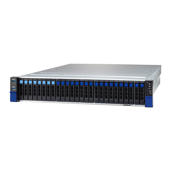
- Page 1 TS75A-B8252 Service Engineer’s Manual...
- Page 2 TECHNOLOGY CORPORATION and has been reviewed for accuracy and reliability prior to printing. MITAC assumes no liability whatever, and disclaims any express or ® implied warranty, relating to sale and/or use of TYAN product including liability or warranties relating to fitness for a particular purpose or merchantability. MITAC retains the right to make changes to produce descriptions and/or specifications at any time, without notice.
- Page 3 FCC Declaration ● Notice for the USA Compliance Information Statement (Declaration of Conformity Procedure) DoC FCC Part 15: This device complies with part 15 of the FCC Rules. This device complies with Part 15 of the FCC Rules. Operation is subject to the following conditions: ‧This device may not cause harmful interference.
- Page 4 Warning This equipment is compliant with Class A of CISPR 32. In a residential environment this equipment may cause radio interference. CAUTION Lithium battery included with this board. Do not puncture, mutilate, or dispose of battery in fire. There will be danger of explosion if battery is incorrectly replaced. Replace only with the same or equivalent type recommended by manufacturer.
- Page 5 How this guide is organized This guide contains the following part: Chapter 1: Overview This chapter provides an introduction to the TYAN TS75A-B8252 barebones and standard par list, describes the external component, gives an overview of the product from different angles.
- Page 6 Safety and Compliance Information Before installing and using TYAN TS75A-B8252, take note of the following precautions: ·Read all instructions carefully. ·Do not place the unit on an unstable surface, cart, or stand. ·Do not block the slot and opening on the unit, which are provided for ventilation.
- Page 7 You must become familiar with the safety information in this guide before you install, operate, or service TYAN product. Symbols on Equipment Caution. This symbol indicates a potential hazard.
- Page 8 · Do not attempt to move a fully loaded rack. Remove equipment from the rack before moving it. · Do not attempt to move a rack on an incline that is greater than 10 degrees from the horizontal. http://www.tyan.com...
- Page 9 This will reduce the risk of personal injury, fire, or damage to the equipment. The total rack load should not exceed 80 percent of the branch circuit rating. Consult the electrical authority having jurisdiction over your facility wiring and installation requirement. http://www.tyan.com...
- Page 10 TYAN, your authorized TYAN partner, or their agent. Equipment Modifications · Do not make mechanical modifications to the system. TYAN is not responsible for the regulatory compliance of TYAN equipment that has been modified.
- Page 11 – Liquid has been spilled on the product or an object has fallen into the product. – The product has been exposed to rain or water. – The product has been dropped or damaged. – The product does not operate normally when you follow the operating instructions. http://www.tyan.com...
-
Page 12: Table Of Contents
Table of Content Chapter 1: Overview ................ 15 About the TYAN TS75A-B8252 ..........15 Product Model ................ 15 Features.................. 16 Standard Par List ..............28 1.4.1 Box Content ..............28 1.4.2 Accessories ..............29 About the Product ..............30 1.5.1 System Front View ............ - Page 13 Finishing Up ................ 107 Appendix I: Installing IO Plate for OCP Card ......108 Appendix II: Cable Connection Tables ........110 Appendix III: Fan and Temp Sensors ........... 112 Appendix IV: FRU Par Table............116 Appendix V: Technical Support ............ 118 http://www.tyan.com...
- Page 14 NOTE http://www.tyan.com...
-
Page 15: Chapter 1: Overview
LRDIMM 3DS MHz memory. Leveraging advanced technology from AMD TS75A-B8252 server system is capable of offering scalable 32 and 64-bit computing, high bandwidth memory design, providing a rich feature set and incredible performance, and lightning-fast PCI-E bus implementation. The TS75A-B8252 not only empowers your company in nowadays IT demand but also offers a smooth path for future application usage. -
Page 16: Features
(26) SATA 6Gb/s Interface External Drive Bay The SAS/SATA HDD backplane is connected to onboard SATA connection by default. Please Notification contact Tyan technical support if a discrete SAS HBA/RAID adapter is required. System Cooling (6) 6cm fans Configuration Type... - Page 17 (1) FH/10.5”L PCI-E Gen4 x16 slot (left) (1) M8252T75-R24-2F riser card for Expansion Slot (1) FH/10.5”L PCI-E Gen4 x16 + Pre-install TYAN Riser Card (1) FH/HL PCI-E Gen4 x8 slot (right) (PCI-E Gen4) (1) M8252T75-L16-1L riser card for (1) HH/HL PCI-E Gen4 x16 slot (left)
- Page 18 24-bit high quality video AST2500 iKVM compression, Support storage Feature over IP and remote platform-flash, Server Management USB 2.0 virtual hub IPMI 2.0 compliant baseboard AST2500 IPMI management controller (BMC), Feature 10/100/1000 Mb/s MAC interface BIOS Brand / ROM size AMI, 32MB http://www.tyan.com...
- Page 19 10° C ~ 35° C (50° F~ 95° F) Operating Non-operating Temp. - 40° C ~ 70° C (-40° F ~ 158° F) Environment In/Non-operating 90%, non-condensing at 35° C Humidity RoHS RoHS 6/6 Compliant Barebone (1) 75A-B8252 Barebone Package Contains Manual (1) Quick Installation Guide http://www.tyan.com...
- Page 20 (18) SATA 6Gb/s + (8) NVMe Interface External Drive Bay The SAS/SATA HDD backplane is connected to onboard SATA connection by default. Please Notification contact Tyan technical support if a discrete SAS HBA/RAID adapter is required. System Cooling (6) 6cm fans Configuration Type...
- Page 21 (1) FH/10.5”L PCI-E Gen4 x16 slot (left) (1) M8252T75-R24-2F riser card for Expansion Slot (1) FH/10.5”L PCI-E Gen4 x16 + Pre-install TYAN Riser Card (1) FH/HL PCI-E Gen4 x8 slot (right) (PCI-E Gen4) (1) M8252T75-L16-1L riser card for (1) HH/HL PCI-E Gen4 x16 slot (left)
- Page 22 24-bit high quality video AST2500 iKVM compression, Support storage Feature over IP and remote platform-flash, Server Management USB 2.0 virtual hub IPMI 2.0 compliant baseboard AST2500 IPMI management controller (BMC), Feature 10/100/1000 Mb/s MAC interface BIOS Brand / ROM size AMI, 32MB http://www.tyan.com...
- Page 23 10° C ~ 35° C (50° F~ 95° F) Operating Non-operating Temp. - 40° C ~ 70° C (-40° F ~ 158° F) Environment In/Non-operating 90%, non-condensing at 35° C Humidity RoHS RoHS 6/6 Compliant Barebone (1) 75A-B8252 Barebone Package Contains Manual (1) Quick Installation Guide http://www.tyan.com...
- Page 24 (18) SATA 6Gb/s + (8) NVMe Interface External Drive Bay The SAS/SATA HDD backplane is connected to onboard SATA connection by default. Please Notification contact Tyan technical support if a discrete SAS HBA/RAID adapter is required. System Cooling (6) 6cm fans Configuration Type...
- Page 25 (1) M8252T75-L24-2F riser card for (2) FH/10.5”L PCI-E Gen4 x8 slot (left) (1) M8252T75-R24-3F riser card for Expansion Slot Pre-install TYAN (2) FH/10.5”L PCI-E Gen4 x8 + Riser Card (1) FH/HL PCI-E Gen4 x8 slot (right) (PCI-E Gen4) (1) M8252T75-L16-2L riser card for...
- Page 26 Server Management USB 2.0 virtual hub IPMI 2.0 compliant baseboard AST2500 IPMI management controller (BMC), Feature 10/100/1000 Mb/s MAC interface Brand / ROM size AMI, 32MB Hardware Monitor, SMBIOS BIOS Feature 3.0/PnP/Wake on LAN, Boot from USB device/PXE via LAN/Storage, http://www.tyan.com...
- Page 27 90%, non-condensing at 35° C Humidity RoHS RoHS 6/6 Compliant Barebone (1) 75A-B8252 Barebone Package Contains Manual (1) Quick Installation Guide NOTE: 1. The specifications are subject to change without prior notice. 2. Please visit our website for the latest specifications. http://www.tyan.com...
-
Page 28: Standard Par List
Standard Par List This section describes TS75A-B8252 package content and accessories. Open the box carefully and ensure that all component are present and undamaged. The product should arrive with packaged as illustrated below. 1.4.1 Box Content If any items are missing or appear damaged, contact your retailer or browse to TYAN’s website for service:... -
Page 29: Accessories
(1) Rail kit and screw (2) CPU Heatsink (2) US power cord (2) EU power cord (1) TYAN Quick Installation Guide (2) M.2 Latch (2) GPU Power Cable (2) GPU Card Bracket ... -
Page 30: About The Product
3.5” /2.5” SSD/HDD/NVMe bays RESET Button NVMe SKU #00 ~ #15 from M/B NVMe port #16 ~ #23 from SAS card (option) #24~ #25 from M/B SATA port LE SKU #00 ~ #19 from M/B SATA port #20~#25 from SAS card (option) http://www.tyan.com... - Page 31 DRIVE STATE Active LED (Green) Status LED (Red) Drive Present, No Active Solid on Drive Present with Active Blinking Don’t care Drive Failure Solid on Don’t care RAID Rebuild Blinking @4 Hz Don’t care Drive Locate Identifier Blinking @1 Hz http://www.tyan.com...
-
Page 32: System Rear View
LP card *1) Dedicated IPMI LAN PCIE Slot #03 (LAN3) Port (FH/HL card *1 or LP card*1) USB3.1 Ports PCIE Slot #02 (LP card *1) USB3.1 Ports PCIE Slot #01 (LP card *1) *LP card=Low profile card http://www.tyan.com... - Page 33 Right LED Link Green 10 Mbps Active Blinking Green Link Green Green 100 Mbps Active Blinking Green Green Link Green Amber 1000 Mbps(1Gps) Active Blinking Green Amber No Link NOTE: “Left” and “Right” are viewed from the rear panel. http://www.tyan.com...
- Page 34 2PSU + 2 AC cord are installed when system PS-ON. Solid on After system operation normally, one of PSU or AC cord be unplug. 1+1 PSU redundancy fail. Warning: All PSUs have to be AC-ON at the same time before you power on the system. http://www.tyan.com...
-
Page 35: System Top View
1.5.3 System Top View http://www.tyan.com... - Page 36 /M1296T65-BP12E-8 /M1298T65-BP12E-2 PSU1 HDD Backplane Board pre-installed (6) System fans PSU0 Memory Slot (2)PCIE4.0 SLOT x24 CPU Socket OCP 3.0 Slot Riser Card Bracket Bracket(M8252T75-L24-2F PCIE4.0 SLOT x16 /M8252T75-L24-1F pre-installed) NOTE: The system is pre-installed with S8252GM2NE-2T system board http://www.tyan.com...
-
Page 37: Chassis Dimensions
1.5.4 Chassis Dimensions http://www.tyan.com... -
Page 38: Chapter 2: Setting Up
Caution! To avoid damaging the motherboard and associated component, use torque force within the range kgf/cm (6.09 lb/in) on each mounting screw for motherboard installation. Do not apply power to the board if it has been damaged. http://www.tyan.com... -
Page 39: Precautions
Working on a system that is connected to a power supply can be extremely dangerous. Follow the guidelines below to avoid damage to TS75A-B8252 or injury to yourself. Ground yourself properly before removing the top cover of the system. -
Page 40: Installing Motherboard Component
CPUs, memory modules and add on cards. 2.1.1 Removing the Chassis Cover Follow these instructions to remove TS75A-B8252 chassis cover. Remove the two screws securing the top cover to the chassis. Press firmly the locking latches. 2. Slide to lift the rear top cover up. -
Page 41: Installing The Cpu And Heatsink
By placing your both index fingers on the sides on the metal handle, pull to release the rail frame. Then lift the rail frame to its fully open position. Remove the external cap from the rail frame. NOTE: Keep the cap for future DOA/RMA usage. http://www.tyan.com... - Page 42 During installation, observe the following: 1. Make sure to push the carrier frame with package towards the end of the rail frame until it clicks into place. 2. Do not drop the carrier frame or touch the package pad to avoid component damage. http://www.tyan.com...
- Page 43 8. Close the force frame. Then use a T20 Torx screwdriver to tighten the screws to secure the force frame in a sequential order (1 ->2->3). 9. Tighten the four screws in a diagonal sequence to secure the heat sink http://www.tyan.com...
-
Page 44: Installing The Memory
2. Align the memory module with the slot. When inserted properly, the memory slot locking levers lock automatically onto the indentations at the ends of the module. Follow the recommended memory population table to install the other memory modules. http://www.tyan.com... -
Page 45: Installing Hard Drives
2.1.4 Installing Hard Drives The TS75A-B8252 support twenty-six 2.5” hot-swap HDD/NVMe SSDs. Installing 2.5” Hot-Swap Hard Drives Follow these instructions to install a 2.5” HDD. Warning!!! Always install the hard disk drive to the chassis after the chassis has been secured on the rack. - Page 46 Open the lock to place the 2.5” hard disk drive into the HDD tray. Push the HDD to the left. Lock the tray lever to secure HDD. Reinsert the HDD tray into the chassis. Push to secure the locking lever until it clicks into place. http://www.tyan.com...
-
Page 47: Installing The Pci-E Card
2.1.5 Installing the PCI-E Card Follow these instructions to install the PCI-E card. There are four expansion slots in the chassis. Unscrew the riser card bracket NO.3. http://www.tyan.com... - Page 48 Unscrew the riser card bracket. 4. Remove the riser card bracket from the chassis. Follow the same procedures to remove the NO.2 riser card bracket from the chassis. http://www.tyan.com...
- Page 49 6. Unscrew to remove the dummy brackets. 7. Insert the PCI-E card into the riser card bracket and screw it firmly. http://www.tyan.com...
- Page 50 8. Reposition and screw the riser card bracket into the chassis. Screw the riser card bracket into the chassis. 10. Follow the same procedures to insert the card to the NO.2 riser card bracket if necessary. http://www.tyan.com...
- Page 51 NO.One or four bracket Unscrew the riser card bracket NO. 4. Remove the riser card brackets for both sides from the chassis. buzou Follow the same procedures to remove the NO.1 riser card bracket from the chassis. http://www.tyan.com...
- Page 52 Unscrew to remove the dummy brackets. Insert the PCI-E card into the riser card bracket and screw it firmly. Reposition the riser card bracket to the chassis and secure the rotate screw firmly. http://www.tyan.com...
- Page 53 Follow the same procedures to insert the card to the NO.1 riser card bracket if necessary. http://www.tyan.com...
-
Page 54: Rack Mounting
Rail screw Pack x 2 2.2.1 Installing the Server in a Rack Follow these instructions to mount the TYAN TS75A-B8252 into an industry standard 19" rack. NOTE: Before mounting the TYAN TS75A-B8252 in a rack, ensure that all internal component have been installed and that the unit has been fully tested. - Page 55 2. Push (a) and slide middle rail back. Install the Inner rail onto the chassis Align the inner sliding rail on the side of the server, and push towards the arrow to secure the hooks. http://www.tyan.com...
- Page 56 Detach inner rail from standoff Loosen screw both sides of the server. Pull the latch upward and remove the keyhole from standoff and slide inner rail forward to remove inner rail. http://www.tyan.com...
- Page 57 Fix the Outer rail/bracket assembly to the frame Please according to the bracket type, and refer to the install/detach instruction. Secure the outer rails to the rack on each side. 2. Please repeat installation steps for the other side. http://www.tyan.com...
- Page 58 Detach bracket from rack post to Release the outer rails from the rack on each side. 2. Please repeat the detach steps for the other side. http://www.tyan.com...
- Page 59 Pull the middle rail fully extended in lock position, ensure ball bearing retainer is located at the front of the middle rail. Horizontally insert the chassis into middle-outer rails. When hit a stop, please pull/push the blue release tab on the inner rails. Tighten chassis with shipping screws. http://www.tyan.com...
-
Page 60: Removing The Server From Rack
2.2.2 Removing the Server from Rack 1. Loosen shipping screws to pull out chassis. 2. Pull the disconnect tab forward to remove chassis at the full extension position. 2. Push tab to slide the middle rail back. http://www.tyan.com... - Page 61 NOTE http://www.tyan.com...
-
Page 62: Chapter 3: Replacing Pre-Installed Component
This chapter explains how to replace the pre-installed component, including the Motherboard, M1717T65-FPB Front Panel Board, M1718T65-USB Board, M1295T65-BP12-8/M1296T65-BP12E-8/M1298T65-BP12-2HDD Backplane, M8252T75-L16-1L M8252T75-L24-1F M8252T75-R24-2F/ M8252T75-R16-1L M8252T75-L16-2L/ M8252T75-R16-2L/ M8252T75-L24-2F M8252T75-R24-3F Riser cards, System fan and Power supply unit etc. Disassembly Flowchart The following flowchart outlines the disassembly procedure. http://www.tyan.com... -
Page 63: Removing The Cover
Removing the Cover Before replacing any par you must remove the chassis cover first. Follow Chapter 2.1.1 to remove the cover of the TS75A-B8252. Replacing Motherboard Component Follow these instructions to replace motherboard component, including the motherboard. 3.4.1 Replacing the Riser Card Follow Chapter 2.1.5 to uninstalling the riser cards of the TS75-B8252. - Page 64 Unscrew the M8252T75-L16-1L riser card to replace with a new one. Follow the steps described earlier in reverse to reinstall the riser card bracket. http://www.tyan.com...
-
Page 65: Pci-E Riser Cards Specification
3.4.2 PCI-E Riser Cards Specification M8252T75-L16-1F M8252T75-L16-1F Riser Card Support (1) PCIE Gen4 slots Features PCIE x16 slot x1 M8252T75-R16-1F M8252T75-R16-1F Riser Card Support (1) PCIE Gen4 slots Features PCIE x16 slot x1 http://www.tyan.com... - Page 66 M8252T75-L16-2L M8252T75-R16-1F Riser Card Support (2) PCIE Gen4 slots Features PCIE x16 slot x1/ PCIE x8 slot x1 M8252T75-R16-2L M8252T75-R16-1F Riser Card Support (2) PCIE Gen4 slots Features PCIE x16 slot x1/ PCIE x8 slot x1 http://www.tyan.com...
- Page 67 M8252T75-L24-1F M8252T75-L24-1F Riser Card Support (1) PCIE Gen4 slots Features PCIE x16 slot x1 M8252T75-R24-2F M8252T75-R24-2F Riser Card Support (2) PCIE Gen4 slots Features PCIE x16 slot x1/ PCIE x8 slot x1 http://www.tyan.com...
- Page 68 M8252T75-R24-3F Riser Card Support (3) PCIE Gen4 slots Features PCIE x16 slot x1/ PCIE x8 slot x2 NOTE: J4 is reserved for PCI-E device which need more power, the power could come from PSU Signal Signal J4 (PWR1) +12V http://www.tyan.com...
-
Page 69: Replacing The Front Panel And Usb Board
Replacing the Front Panel and USB Board Follow these instructions to replace the Front Panel and USB Board. Unscrew to remove the Front Panel and USB Board cover. Remove the Front Panel Board cover. http://www.tyan.com... - Page 70 Disconnect the FP cable and then unscrew the front panel board for replacement. Disconnect the USB Board to replace a new one. Follow the procedure described earlier in reverse order to reinstall the Font Panel Board and USB Board into the chassis. http://www.tyan.com...
-
Page 71: Replacing The System Fan
Replacing the System Fan Follow these instructions to replace the fan. Take out the fan from the chassis. Replace a new fan to the chassis. Reinstall a new fan to the chassis. http://www.tyan.com... -
Page 72: Replacing The Hdd Backplane Board
Disconnect all cables connected to the M1295T65-BP12-8/M1296T65-BP12E-8/ M1298T65-BP12E-2 HDD backplane Board. Unscrew the HDD BP Board. Release the HDD Backplane from the hook. Follow the procedures described earlier to reinstall the HDD backplane board bracket into the chassis. http://www.tyan.com... -
Page 73: Hdd Backplane Board Features
M1295T65-BP12-8 Front View Rear View PCB Dimensions: 131mm*76mm*3mm Form Factor Thickness: 3mm Layer: 6 layers 10-Pin FAN Header x 1 Specifications Mini SAS HD Connector x 2 (Input) Overview 5-Pin SGPIO Header x 1 SATA/SAS HDD x 8 (Output) http://www.tyan.com... -
Page 74: Connector Definition
SGPIO Header for HDD0~7 SGPIO1 Reserved NOTE: The location, rebuilding, group raid and lamp function will be normally. When use LSI MR SAS 9361-8I Raid Card, the HDD backplane 3PHD_1 jumper need to be set to LSI Raid Mode. http://www.tyan.com... - Page 75 PCB Dimensions: 131mm*76mm*3mm Form Factor Thickness: 3mm Layer: 8 layers 10 Pin FAN Header x 1 SlimSAS Connector x4 Input Specifications 5Pin SGPIO Header x 2 Overview NVMe HDD x 8 (Output) Smbus Header x1 (HDR_1) FAN Connector x 3 http://www.tyan.com...
-
Page 76: Hdd Backplane Features
4P Power CON (PW1) Header for PCA9544 SMBUS address Select (3PHD-1) The rear 2 SATA SSDs/HDDs (SATA0 & SATA1) are not available when AMD EPYC™ 7002 Series Processors deployed in all configurations. Please contact Tyan Technical Support for more details. http://www.tyan.com... -
Page 77: Replacing The Power Supply
Follow these instructions to replace the power supply module in your system. Press the latch to pull the power supply out. After replacing a new power supply, press and hold the latch to push the power supply back into the chassis. http://www.tyan.com... -
Page 78: Disconnecting All Motherboard Cables
3.10 Disconnecting All Motherboard Cables Disconnect slim SAS cables connected to the motherboard. Disconnect slim SAS and power cables connected to the motherboard. http://www.tyan.com... -
Page 79: Removing The Motherboard
After removing all of the aforementioned cables, follow the instructions below to remove the motherboard from the chassis. Remove the air duct, processor and heatsink if installed. Remove three screws securing the bar from the chassis. Unscrew the five studs with the Hex Socket Screwdriver. http://www.tyan.com... - Page 80 Carefully lift the motherboard from the chassis. Unscrew the 16 screws with the Screwdriver. http://www.tyan.com...
- Page 81 NOTE http://www.tyan.com...
-
Page 82: Chapter 4: Installing Gpu Cards
T4 GPU card The TN75-B8252 supports four PCI-E Riser Card Brackets. Follow these instructions to install GPU card in your system. Unscrew the riser card bracket. Release the riser card bracket from the chassis. Remove the dummy bracket from the riser. http://www.tyan.com... - Page 83 Insert the tesla T4 GPU card and secure the tesla T4 GPU card to the riser. Reinstall the bracket to the chassis. Unscrew the riser card bracket. http://www.tyan.com...
- Page 84 Insert the tesla T4 GPU card and secure the tesla T4 GPU card to the riser. Reinstall the bracket to the chassis. http://www.tyan.com...
- Page 85 Secure GPU card onto the left and right riser card and secure the three screws and one rotary screw on both sides to the bracket. http://www.tyan.com...
-
Page 86: Installing The Nvidia Rtx6000 Gpu Card
Install the GPU card to the GPU bracket, and then secure the GPU card to the bracket with the four screws (2 screws for the front side of the bracket and 2 short screws for the rear side of the bracket). http://www.tyan.com... - Page 87 Connect the GPU power cable onto the GPU card to the bracket. Reposition GPU card to the riser bracket and secure the three screws as in the image. http://www.tyan.com...
- Page 88 Secure the two rotary screws. Reconnect the GPU power cables to the bracket. http://www.tyan.com...
-
Page 89: Chapter 5: Motherboard Information
Caution! To avoid damaging the motherboard and associated components, do not use torque force greater than 7kgf/cm (6.09 lb/in) on each mounting screw for motherboard installation. Do not apply power to the board if it has been damaged. http://www.tyan.com... -
Page 90: Board Image
Board Image S8252GM2NE-2T This picture is representative of the latest board revision available at the time of publishing. The board you receive may not look exactly like the above picture. http://www.tyan.com... -
Page 91: Block Diagram
Block Diagram S8252 Block Diagram http://www.tyan.com... -
Page 92: Motherboard Mechanical Drawing
Motherboard Mechanical Drawing http://www.tyan.com... -
Page 93: Board Parts, Jumpers And Connectors
The board you receive may not look exactly like the above diagram. The DIMM slot numbers shown above can be used as a reference when reviewing the DIMM population guidelines shown later in the manual. For the latest board revision, please visit our web site at http://www.tyan.com. http://www.tyan.com... - Page 94 10. X550 LAN Connector(X550_LAN1) 41. SYS_FAN_4 (SYS_FAN_4) 11. CPLD Flash FW(JTAG1) 42. SYS_FAN_3 (SYS_FAN_3) 43. Slim SAS CON(PCIE) (Slim SAS3) 12. TYAN Module Header (DBG_HD1) 13. IPMI LAN Connector(BMC_LAN) 44. Slim SAS CON(PCIE) (Slim SAS4) 45. SYS_FAN_2 (SYS_FAN_2) 14. USB3.0 x2 (USB3_2) 15.
- Page 95 SATA ACT LED (LED7) vii.BMC Heartbeat LED(BMC_HBLED) xvii. SATA ACT LED (LED8) Viii CPLD STATUS LED(LED2) xviii. SATA ACT LED (LED9) ix. CPLD RCR ERROR LED(LED1) Jumper Legend OPEN - Jumper OFF Without jumper cover CLOSED - Jumper ON With jumper cover http://www.tyan.com...
- Page 96 CPU1_FAN_1: CPU1 FAN Connector COM2/5 / COM1: COM1/2 Port Header Signal Signal FPIO_2: Front Panel Header Signal Signal PW_LED+ VDD3_DUAL IDLED+ PW_LED- IDLED- HD_LED+ HW_FAULT1- HD_LED- SYS_FAULT2- PW_SW# LAN0_LED LAN0_LED- RST_SW# SMBDATA SMBCLK IDLED_SW# INTRUDER# SYS_Air_Inlet LAN1_LED+ NMI_SW# LAN1_LED- http://www.tyan.com...
- Page 97 SSRX- SSRX+ USB DATA2- USB DATA2+ SSTX- SSTX+ SGPIO Header (P0_SATA_SGPIO0/ P0_SATA_SGPIO1/ P1_SATA_SGPIO1) Signal Signal SDIN DATA SDOUT SLOAD SCLOCK VDD3_DUAL DBG_HD1: TYAN Module Header Signal Signal P3V3 FRAME_N LAD0 LAD1 PLT_RST_N LAD2 LAD3 CLK_33M DBG_SERIRQ DBG_PRES_N VCC3_AUX TPM_ADDR_MB PCH_TPM_PP_EN...
- Page 98 TACH_SYS1 TACH_SYS6 TACH_SYS2 TACH_SYS7 TACH_SYS3 TACH_SYS8 TACH_SYS4 TACH_SYS9 TACH_SYS5 TACH_SYS10 PWM_SYS2 PWM_SYS1 TACH_SYS11 BMC_DAT3 TACH_SYS12 BMC_CLK3 VDD3_DUAL PWM_SYS3 VDD3_DUAL TACH_SYS13 TACH_CPU1 TACH_SYS14 TACH_CPU0 PWM_SYS4 PWM_SYS5 PWM_CPU0 J20/J25/J26/J27: 7 Pin Header for hot plug Signal Signal VDD_33_Dual HP_CLK HP_DATA HP-ALERT http://www.tyan.com...
- Page 99 P12_HDD2 P12_HDD2 PE_PW3: 8-pin Power Connector to HDD BP Signal Signal P12_HDD3 P12_HDD3 P12_HDD3 P12_HDD3 NOTE: The 8-pin GPU power connector can support up to 20A. PE_PW4: 8-pin Power Connector to GPU Card Signal Signal P12_GPU1 P12_GPU1 P12_GPU1 P12_GPU1 http://www.tyan.com...
- Page 100 PE_PW5: 8-pin Power Connector to GPU Card Signal Signal P12_GPU2 P12_GPU2 P12_GPU2 P12_GPU2 HD_PW1/HD_PW2: 8-pin Power Connector to GPU Card Signal Signal P12V_HD P12V_HD P12V_HD P12V_HD HD_PW3: 8-pin Power Connector to GPU Card Signal Signal VDD_12_PSU VDD_5_RUN SHD_PW4/ SHD_PW5/ SHD_PW6/ SHD_PW7/SHD_PW8 Signal Signal VDD_12_PSU VDD_5_RUN http://www.tyan.com...
-
Page 101: Thermal Interface Material
CPU lid (applying too much will actually reduce the cooling). NOTE: Always check with the manufacturer of the heat sink & processor to ensure that the thermal interface material is compatible with the processor and meets the manufacturer’s warranty requirements. http://www.tyan.com... -
Page 102: Tips On Installing Motherboard In Chassis
Be especially careful to look for extra stand-offs. If there are any stand-offs present that are not aligned with a mounting hole on the motherboard, it will likely short components on the back of the motherboard when installed. This will cause malfunction and/or damage to your motherboard. http://www.tyan.com... - Page 103 Some chassis include plastic studs instead of metal. Although the plastic studs are usable, MITAC recommends using metal studs with screws that will fasten the motherboard more securely in place. Below is a chart detailing what the most common motherboard studs look like and how they should be installed. http://www.tyan.com...
-
Page 104: Installing The Memory
Installing the Memory Before installing memory, ensure that the memory you have is compatible with the motherboard and processor. Check the TYAN Web site at http://www.tyan.com details of the type of memory recommended for your motherboard. (16+16) DIMM slots support /(L)RDDR4 up to 3200 w/ ECC (1.2V) ... - Page 105 Populating NVDIMMs NVDIMMs are identical only per channel pair. D-R,LR, or 3DS DIMM type Populating NVDIMMs with capacity-2x D RDIMMs or capacity LRDIMMs Table2.DIMM Interleaving Guidelines Slots DIMMs DIMM Frequency(MT/s) Populated 1.2V 2667 2667 2667 2400 2133 2133 2133 http://www.tyan.com...
- Page 106 √ √ P1_D3_UMC0_CH_E0 √ √ √ √ √ √ √ P1_D3_UMC0_CH_E1 √ P1_D3_UMC1_CH_F0 √ √ √ √ √ P1_D3_UMC1_CH_F1 √ √ √ P1_D2_UMC1_CH_G0 √ √ √ √ √ √ √ P1_D2_UMC1_CH_G1 √ P1_D2_UMC0_CH_H0 √ √ √ √ √ P1_D2_UMC0_CH_H1 http://www.tyan.com...
-
Page 107: Finishing Up
In the rare circumstance that you have experienced difficulty, you can find help by asking your vendor for assistance. If they are not available for assistance, please find setup information and documentation online at our website or by calling your vendor’s support line. http://www.tyan.com... -
Page 108: Appendix I: Installing Io Plate For Ocp Card
1. Use a screwdriver to remove the dummy cover for the OCP card slot. 2. Press to right and forward to release the dummy cover for the OCP card slot. 3. Insert the OCP 3.0 card into the OCP slot http://www.tyan.com... - Page 109 4. Secure the OCP 3.0 card to the chassis 5. The OCP 3.0 card to the chassis has been completed. http://www.tyan.com...
-
Page 110: Appendix Ii: Cable Connection Tables
Front Backplane (BP) Board to S8252MB HDD BP 1 Cable Connect to S8252GM2NE-2T/MB M1295T65A-BP12-8 SATA0-3 SlimSAS 8I to Mini-SAS SATA4-7 Power Cable PE_PW1 Front Backplane (BP) Board to S8252MB Cable HDD BP 2 Connect to S8252GM2NE-2T/MB http://www.tyan.com... - Page 111 SATA 7P to SATA 7P SATA1 SHD PW4 MICRO-FIT 1*4P HDR 7P Cable HDR1 Front Panel Control Cable Front Panel Connect to S8252GM2NE-2T/MB M1718T65-FPB FPIO_2 Front Panel USB Cable Front Panel Connect to S8252GM2NE-2T/MB M1717T65-USB USB3_FPIO1 http://www.tyan.com...
-
Page 112: Appendix Iii: Fan And Temp Sensors
CPU0_FAN/CPU1_FAN,, which detect the fan speed (rpm) Temp Sensor: OCP_Air_Inlet(U13),and MB_Air_Inlet(RT2) etc. They detect the system temperature around. NOTE: The system temperature is measured in a scale defined by AMD, not in Fahrenheit or Celsius. http://www.tyan.com... - Page 113 BIOS Temp Sensor Name Explanation: http://www.tyan.com...
- Page 114 The highest temperature of CPU0 UMC3 channel C slot P0_UMC2_CH_D The highest temperature of CPU0 UMC2 channel D slot P0_UMC6_CH_E The highest temperature of CPU0 UMC6 channel E slot P0_UMC7_CH_F The highest temperature of CPU0 UMC7 channel F slot http://www.tyan.com...
- Page 115 Fan speed of SYS_FAN_1 SYS_FAN_2 Fan speed of SYS_FAN_2 SYS_FAN_3 Fan speed of SYS_FAN_3 SYS_FAN_4 Fan speed of SYS_FAN_4 SYS_FAN_5 Fan speed of SYS_FAN_5 SYS_FAN_6 Fan speed of SYS_FAN_6 PSU0_FAN Fan speed of PSU0_FAN PSU1_FAN Fan speed of PSU1_FAN http://www.tyan.com...
-
Page 116: Appendix Iv: Fru Par Table
FRU-RC-1020 411T61500009 M8252T75-L16-2L-B R01 FRU-RC-1030 411T61500021 M8252T75-L24-2F-B FRU-RC-1040 411T61500015 M8252T75-R16-2L-B FRU-RC-1050 411T61500027 M8252T75-R24-3F-B PCBA Riser boards FRU-RC-1060 411T61500052 M8252T75-R24-2F-B FRU-RC-1070 411T61500051 M8252T75-R16-1L-B FRU-RC-1080 411T61500049 M8252T75-L24-1F-B FRU-RC-1090 411T61500050 M8252T75-L16-1L-B TF-SLIDE RAIL KIT;SBU,TOOLLESS, RackMounting FRU-AS-0181 452T61300002 WITH LOCKIN, SGCC+STEEL+SCREW, Parts Travel818,TN83-B8251 http://www.tyan.com... - Page 117 MiniSAS CABLE,SlimSAS 8i 74P/MiniSAS FRU-CS-1260 422T60900008 36P*2,TS65-B8036,HDD BP MiniSAS<=>MB SlimSAS-J12,J56 System FRU HDD Tray kit for TS75-B8252 & TS75A-B8252; 2.5" HDD tray kit; RoHS FRU-SO-9290 5412T6150007 Max. up to two sets of FRU-SO-9290 are supported in the TS75-B8252 system. 200mm,GPU PWR...
-
Page 118: Appendix V: Technical Support
MITAC serves multiple market segment with the industry’s most competitive services to support them. TYAN's tech support is some of the most impressive we've seen, with great response time and exceptional organization in general.” — Anandtech.com Please feel free to contact us directly for this service at tech-support@tyan.com... - Page 119 Return Merchandise Authorization (RMA) number. The RMA number should be prominently displayed on the ouide of the shipping carton and the package should be mailed prepaid. TYAN will pay to have the board shipped back to you. ® TS75A-B8252 Service Engineer’s Manual V1.0a...
Need help?
Do you have a question about the TS75A-B8252 and is the answer not in the manual?
Questions and answers