Table of Contents
Advertisement
Quick Links
Advertisement
Table of Contents

Subscribe to Our Youtube Channel
Related Manuals for TYAN Tank TA26 B5380


Summary of Contents for TYAN Tank TA26 B5380
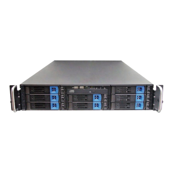
- Page 1 Tank TA26 B5380 Service Engineer’s Manual...
-
Page 3: Table Of Contents
Chapter 1: Overview 1.1 About the TYAN Tank TA26-B5380 ..... . . 1 1.2 Product Models ........2 1.3 Features . - Page 4 3.4.2 Removing the Motherboard ......40 3.5 Replacing the Slim DVD-ROM ......41 3.6 Replacing the LED Control Board .
- Page 5 TYAN retains the right to make changes to product descriptions and/or specifications at any time, without notice. In no event will TYAN be held liable for any direct or indirect, incidental or consequential damage, loss of use, loss of data or other malady resulting from errors or inaccuracies of information contained in this document.
- Page 6 Federal Communications Commission (FCC) Notice for the USA Compliance Information State- ment (Declaration of Conformity Procedure) DoC FCC Part 15: This device complies with part 15 of the FCC Rules Operation is subject to the following conditions: 1) This device may not cause harmful interference, and 2) This device must accept any interference received including inter- ference that may cause undesired operation.
- Page 7 About this Manual This manual provides you with instructions on installing your Tank TA26-B5380. This manual is intended for experienced users and integrators with hardware knowledge of personal computers. This manual consists of the following parts Provides an Introduction to the TA26-B5380 bare- Chapter 1: bone, packing list, describes the external compo- nents, gives a table of key components, and...
- Page 8 SAFETY INFORMATION Before installing and using the TA26-B5380, take note of the follow- ing precautions: – Read all instructions carefully. – Do not place the unit on an unstable surface, cart, or stand. – Do not block the slots and opening on the unit, which are pro- vided for ventilation.
-
Page 9: Chapter 1: Overview
IT environment but also offers a smooth path for future application usage. TYAN is also proud to deliver the Tank TA26-B5380 in SAS/SATA flavor while supporting up to eight (8) hot-swap hard drives and one (1) slim DVD-ROM drive. The Tank TA26-B5380 uses TYAN’s latest tooling-made chassis featur-... -
Page 10: Product Models
Product Models Power Model HDD Bays Backplane Supply 8-port Single B5380T26V8H SAS/SATA 600W 8-port 600W (1+1) B5380T26V8HR SAS/SATA redundant Chapter 1: Overview... -
Page 11: Features
(660x432x88mm) from Blackford MCH) • Two (2) PCI-X 64/133MHz slots Motherboard • Supports a total of five (5) low- • TYAN Tempest i5000PX profile expansion cards S5380G2NR • Extended ATX footprint (12” x 13”) Back I/O Ports • One keyboard & one PS/2 mouse... - Page 12 Server Management • Automatic fan speed control • Chassis intrusion alert • Supports TYAN Server Management (TSM) • Optional TYAN SMDC M3291, IPMI v2.0 compliant remote server management kit Power Supply • EPS 12V, 2U, 600W with PFC for B5380T26V8H •...
-
Page 13: Unpacking
1.4.1 Box Contents Component Description Industry standard 2U chassis, (8) hot-swap HDD bays TYAN Tempest i5000PX S5380G2NR mother- board (pre-installed) Slim DVD-ROM drive (pre-installed) LED and USB control board (pre-installed) EPS 12V, 2U, 600W PSU with PFC (pre-installed) (A) (B5380T26V8H models) -
Page 14: Accessories
If any items are missing or appear damaged, contact your retailer or browse to TYAN’s Web site for service: http://www.tyan.com. The Web site also provides information on other TYAN prod- ucts, plus FAQs, compatibility lists, BIOS settings, and more. 1 x TYAN Driver CD... - Page 15 Screw Pack Brackets FDD Power Cable Sliding Rail TYAN Logo Chapter 1: Overview...
-
Page 16: About The Product
About the Product The following views show you the product. 1.5.1 System Front View Reset switch ID switch Power LED Power switch Warning LED HDD activity LED USB ports LAN LEDs ID LED HDD Tray DVD-ROM drive Power LEDs Hard Drive Bay x 8 HDD Tray Activity LEDs 1.5.2 System Rear View... -
Page 17: Led Definitions
1.5.3 LED Definitions Front Panel Color State Description Power Green Power ON Power OFF HDD Activity Amber Blinking HDD/DVD-ROM access activity No disk activity LAN1/LAN2/Linkage Green LAN linked Green Blinking LAN accessing No LAN linked Fail System fails Abnormal power off Normal Hot Swappable HDD Green... -
Page 18: Motherboard Layout
1.5.4 Motherboard Layout Chapter 1: Overview... -
Page 19: Jumpers & Connectors
1.5.5 Jumpers & Connectors Jumper/Connector Function Onboard VGA Jumper - Open: Enable VGA (Default) - Closed: Disable VGA COM2 Header Fan Connector (for barebone use only) IPMB Connector J7/J44/J68 Chassis Fan Connectors J7: FAN1, J44: FAN3, J68: FAN2 J39/J40 CPU Fan Connectors J39: CPUFAN1 J40: CPUFAN0 Chassis LCD Module Interface Header IDE Connector... -
Page 20: System Block Diagram
1.5.6 System Block Diagram Chapter 1: Overview... -
Page 21: Internal View
1.5.7 Internal View 1. Memory Slots 9. System Fans 2. Power Connector 10. SAS / SATA Cables (6) 3. Power Supply 11. PCI-E Slot 4. CPU0 / CPU1 12. PCI-E Slot 5. SAS / SATA Backplane 13. PCI-E Slot 6. LED Control Board Cable 14. - Page 22 Chapter 1: Overview...
-
Page 23: Chapter 2: Setting Up
Chapter 2: Setting Up 2.0.1 Before You Begin This chapter explains how to install the CPU, CPU heatsink, memory modules, and hard drives. Instructions on inserting a PCI card are also given. Take note of the precautions mentioned in this section when installing your system. -
Page 24: Precautions
2.0.4 Precautions Components and electronic circuit boards can be damaged by discharges of static electricity. Working on a system that is connected to a power supply can be extremely dangerous. Follow the guidelines below to avoid damage to the Tank TA26-B5380 or injury to yourself. •... -
Page 25: Rack Mounting
Rack Mounting After installing the necessary components, the Tank TA26- B5380 can be mounted in a rack using the supplied rack mounting kit. Rack mounting kit Sliding Rails x 2: Mounting Ears x 2 Screws Kit x 1 Mounting Brackets x 4 (pre-installed) 2.1.1 Installing the Server in a Rack Follow these instructions to mount the TA26-B5380 into an industry standard 19"... - Page 26 Attaching the Inner Rails to the Unit 1. Screw the handles to each side of TA26-B5380 as shown using two (2) M4L6, S10C screws (A) from the supplied screws kit. 2. Attach the inner rails both sides of the unit using nine (9) M4, L5 screws (C) on each side.
- Page 27 2. Secure the outer rail to the rack using 2 brackets and M6 screws (B) for each side. Secure the mounting brack- ets from inside, not outside, of the rack. Chapter 2: Setting Up...
- Page 28 Rackmounting the Server 1. Draw out the middle rail to the latch position. 2. Lift the unit and then insert the inner slide rails into the middle rails. 3. Push the unit in and press the latch key. Chapter 2: Setting Up...
- Page 29 4. Push the whole system into the rack. 5. Secure the mounting handles of the unit to the rack. To avoid injury, it is strongly recommended that two Note: people lift the TA26-B5380 into the place while a third person screws it to the rack.
-
Page 30: Installing Motherboard Components
Installing Motherboard Components This section describes how to install components on to the motherboard, including CPU, memory modules and PCI card. 2.2.1 Removing the Chassis Cover Follow these instructions to remove the Tank TA26-B5380 chassis cover. 1. Turn the screw on the back side. Then slide the chassis cover in the direction of arrow. -
Page 31: Installing The Cpu
2.2.2 Installing the CPU Follow these instructions to install the CPU. 1. Remove the cover on the CPU socket. 2. Lift up the CPU lever to unlock the socket. 3. Open the socket in the direction as illustrated. Chapter 2: Setting Up... - Page 32 4. Place the CPU in the CPU socket, ensuring that pin 1 is located as shown below. 5. Close the cover and press the CPU socket lever down to secure the CPU. 6. Place the fan and heatsink on top of the CPU and attach with two screws as shown below.
- Page 33 7. Attach the fan power cable to the connector on the motherboard as shown. 8. Repeat these steps when installing a second CPU. Chapter 2: Setting Up...
-
Page 34: Installing The Memory
2.2.3 Installing the Memory Follow these instructions to install the memory modules on the motherboard. 1. Locate the memory slots on the motherboard. 2. Press the memory slot locking levers in the direction of the arrows as shown below. 3. Align the memory module with the slot. The module has indentations that align with notches in the slots. - Page 35 The following chart outlines the suggested rules for populating memory. Channel Single Dual Four Four DIMM DIMMA0 DIMMA1 DIMMB0 DIMMB1 DIMMC0 DIMMC1 DIMMD0 DIMMD1 Note: 1. X indicates a populated DIMM slot. 2. Always install memory beginning with DIMMA0. You can choose to install single, dual or four memory modules.
-
Page 36: Installing Pci Cards
2.2.4 Installing PCI Cards The TA26-B5380 has five PCI card slots: 3 x PCI-E card slots 2 x PCI-X card slots Follow these instructions to install any of the above kinds of PCI cards. 1. Unscrew the bracket covering the PCI card slots as shown. -
Page 37: Installing Hard Drives
2.2.5 Installing Hard Drives The TA26-B5380 supports up to eight serial SAS/SATA hard drives. Follow these instructions to install a hard drive. 1. Press the locking lever latch in the direction shown by the arrow below. The latch will pop open. 2. - Page 38 4. Remove the base. 5. Place a hard drive into the drive tray. 6. Screw the hard drive in place using 4 HDD screws. Chapter 2: Setting Up...
- Page 39 7. Reinsert the tray into the bay and press the locking lever to secure. Chapter 2: Setting Up...
-
Page 40: Installing A Floppy Drive
2.2.6 Installing a Floppy Drive This section describes how to install a floppy disk drive in the TA26-B5380 if required. Follow these instructions to install a floppy disk drive in the TA26-B5380. 1. Remove the top, left hand drive tray from the TA26- B5380 as shown. - Page 41 The FDD rails each have a flat side which should be Note: against the body of the floppy drive when installed. There is also a spring catch mechanism on the right hand rail (when looking at the floppy disk drive from the front). 3.
- Page 42 To release the floppy disk drive from the drive bay, Note: you will need to press the release catch inside the chassis. Chapter 2: Setting Up...
-
Page 43: Chapter 3: Replacing Pre-Installed Components
Chapter 3: Replacing Pre-Installed Components Introduction This chapter explains how to replace pre installed compo- nents including the motherboard, LED control board, USB adapter board, HDD, and DVD-ROM drive, etc. Take note of the precautions in this section when installing your system. -
Page 44: Precautions
3.1.3 Precautions Components and electronic circuit boards can be damaged by static electricity. Working on a system that is connected to a power supply can be extremely dangerous. Follow the guidelines below to avoid damage to the Tank TA26-B5380 or injury to yourself. -
Page 45: Disassembly Flowchart
Disassembly Flowchart The following flowchart outlines the disassembly procedure. Rear Components DIMMs Chassis top cover CPU/heatsink assembly Mainboard PCI card Power supply Mainboard Front Components Chassis top cover PCBs DVD-ROM Control Backplane Board The Tank TA26-B5380 should be always powered off Note: before disassembly. -
Page 46: Removing The Cover
Removing the Cover Before replacing any parts you must remove the chassis cover. Follow these instructions to remove the cover of the Tank TA26-B5380 chassis cover. 1. Remove the screw on the back side. Then slide the chas- sis cover in the direction of arrow. 2. -
Page 47: Replacing Motherboard Components
Replacing Motherboard Components Follow these instructions to replace motherboard compo- nents, including the motherboard. 3.4.1 Disconnecting All Motherboard Cables Before replacing the motherboard or certain components, remove cables connected to the motherboard. Follow these instructions to remove all motherboard cabling. 1. -
Page 48: Removing The Motherboard
3.4.2 Removing the Motherboard After removing all of the aforementioned cables, follow these instructions to remove the motherboard from the chassis. 1. Remove the ten screws securing the motherboard to the chassis. 2. Remove the motherboard. Chapter 3: Replacing Pre-Installed Components... -
Page 49: Replacing The Slim Dvd-Rom
Replacing the Slim DVD-ROM Follow these instructions to replace the DVD-ROM. 1. Remove the power / data cable from the rear of the DVD- ROM drive. 2. Press the tab in the direction shown to release the DVD- ROM drive. 3. - Page 50 4. Remove the two screws that secure DVD-ROM drive to the bracket. 5. Replace the DVD-ROM drive. 6. Secure the DVD-ROM to the bracket using two screws. Then replace the unit into the drive bay and connect the DVD-ROM power and data cable. Chapter 3: Replacing Pre-Installed Components...
-
Page 51: Replacing The Led Control Board
Replacing the LED Control Board Follow these instructions to replace the LED control board. 1. Remove the screw securing the LED control board unit to the chassis. 2. Remove the connector cables from the backplane. 3. Slide back the LED control board bracket and lift free of the chassis. - Page 52 4. Remove the LED control board and USB cables from the LED control board/USB adapter board. 5. Remove the five screws securing the LED control board/ USB adapter board to the bracket. 6. Release the LED control board/USB adapter board from bracket.
-
Page 53: Replacing The Backplane
Replacing the Backplane Follow these instructions to replace the backplane in your TA26-B5380 system. 1. Remove all of cables connected to the backplane, includ- ing fan cables, DVD-ROM cable, Control board cable, fan control cable, USB cable, front panel LED cables, power cables, and SATA cables. - Page 54 2. Remove the ten screws to release the backplane. 3. Turn the locking keys at the base of the backplane. 4. Pull out the backplane. Chapter 3: Replacing Pre-Installed Components...
-
Page 55: Backplane Features For Ta26-B5380
3.7.1 Backplane Features for TA26-B5380 Front View J35 2x7pin J13 29pin SAS J14 29pin SAS J15 29pin SAS J34 2x5pin LED J11 29pin SAS J12 29pin SAS J7 40pin cd-rom/B J33 2x12pin LED/B J5 2x5pin USB J36 2x7pin J8 29pin SAS J9 29pin SAS J10 29pin SAS Chapter 3: Replacing Pre-Installed Components... -
Page 56: Rear View
Rear View J1,J2,J3 big 4pin FAN1 4pin J25,J27,J29,J31 7pin secondary J6 TO J24,J26,J28,J30 CD-ROM 7pin primary FAN2 4pin J38 2x7pin tach and PWM J37 small 4pin FAN3 4pin J17,J19,J21,J23 J32 LED/B 7pin secondary J16,J18,J20,J22 7pin primary J4 USB OUT Chapter 3: Replacing Pre-Installed Components... -
Page 57: Backplane Connector Pin Definitions
3.7.2 Backplane Connector Pin Definitions J32, J33 2x12pin LED board connector LAN1 LED + (link/active) LAN1 LED - (link/active) Reserved Reserved LAN2 LED + (link/active) LAN2 LED - (link/active) Reserved Reserved Reserved Reserved ID-LED + ID-LED - W-LED + W-LED - M/B HDD LED + M/B HDD LED - M/B power LED +... - Page 58 DIOR IORDY CSEL DMACK INTRQ IOCS16 PDIAG CS1FX CS3FX DASP Fan Signal Related Connector Pin Definitions The FAN signal naming is based on HW circuit Note: design only. It might be different from the system fan name. FAN1, FAN2, FAN3: 4-pin Fan connector VDD +12V TACH J1, J2 and J3 power big 4-pin connector...
- Page 59 J4, J5 USB 2x5pin connector USB1 power + USB2 power + USB1 DATA - USB2 DATA - USB1 DATA + USB2 DATA + USB1 GND USB2 GND Key pin None J37 power small 4-pin connector +12V J36 HDD LED pin out PLED1 ALED1 ALED1 +...
- Page 60 J35 HDD LED pin out PLED6 + ALED6 - ALED6 + PLED7 + ALED7 - ALED7 + PLED8 + ALED8 - ALED8 + None J38 2x7pin FAN tach and PWM pin out FAN1 tach Reserved FAN2 tach Reserved FAN3 tach Reserved Reserved Reserved...
-
Page 61: Replacing The System Fan
Replacing the System Fan Follow these instructions to replace the cooling fans in your TA26-B5380 system. 1. Locate the fan connector on the backplane and unplug the fan cable as shown below. 2. Take the fan away from the chassis. 3. -
Page 62: Replacing The Power Supply
Replacing the Power Supply Follow these instructions to replace the power supply in your TA26-B5380 system. 3.9.1 Standard Power Supply 1. Remove the chassis cover. See “Removing the Cover” on page 38 for more details. 2. Detach the power cables from the motherboard and backplane. -
Page 63: Optional 1+1 Redundant Power Supply
4. Remove the two screws attaching the power supply to the chassis interior and lift out the unit. 3.9.2 Optional 1+1 Redundant Power Supply If the optional 1+1 redundant power supply is fitted, either of the two units can be hot swapped. Follow these instructions to replace a single power unit with a redundant power supply unit. - Page 64 2. Remove the screws which fix the bracket to the sides of the redundant power supply casing. 3. Screw the bracket to the rear of the power supply casing. 4. Insert the redundant power supply casing into the chas- sis, making sure it is aligned as shown. Chapter 3: Replacing Pre-Installed Components...
- Page 65 5. Screw the casing to the chassis exterior. 6. Screw the casing to the chassis interior. 7. Fix the redundant power supply switch to the chassis rear window with two Hex #6-32 screws. Chapter 3: Replacing Pre-Installed Components...
- Page 66 8. Insert the new power supply unit and secure by turning the locking screw. 9. Re-attach all power supply connector cables to the moth- erboard and backplane. Chapter 3: Replacing Pre-Installed Components...
-
Page 67: Appendix I: Bios Differences
Appendix I: BIOS Differences The BIOS of B5380 is similar to the BIOS of S5380. There is only one menu different. See the following for the differences in BIOS between B5380 and S5380. For a complete review of S5380 BIOS, refer to the motherboard manual. B5380 Advanced/Hardware Health Configuration PhoenixBIOS Setup Utility Advanced... - Page 68 S5380 Advanced/Hardware Monitor Configuration PhoenixBIOS Setup Utility Advanced Hardware Monitor Item Specific Help Voltage Monitoring CPU0 Fan xxxx RPM CPU1 Fan xxxx RPM FAN1 xxxx RPM FAN2 xxxx RPM FAN3 xxxx RPM CPU0 Temp. = xx ºC/ xxx ºF System Temp. = xx ºC/ xxx ºF Auto Fan Control [Disabled]...
-
Page 69: Appendix Ii: Cable Connection Tables
Appendix II: Cable Connection Tables SAS/SATA Cable Table 1: TA26-B5380 Model SAS/SATA Backplane Connects to Motherboard SATA0 SATA1 SATA2 SATA3 SATA4 SATA5 FAN Cable Table 2: System Fan to Backplane System Fan Connects to Backplane Fan 1 FAN1 4-pin connector Fan 2 FAN2 4-pin connector Fan 3... - Page 70 Table 4: Power Supply to Backplane Power Supply Connects to Backplane P3 4-pin power cable J1 4-pin connector P3 4-pin power cable J2 4-pin connector P3 4-pin power cable J3 4-pin connector Other Cables Table 5: Backplane to Motherboard Backplane Connects to Motherboard J32 LED/B...
-
Page 71: Technical Support
(which can have expensive consequences). If these options are not available for you then TYAN Com- puter Corporation can help.Besides designing innovative and quality products for over a decade, TYAN has continuously offered customers service beyond their expectations. - Page 72 RMA number should be prominently displayed on the outside of the shipping carton and the package should be mailed pre- paid. TYAN will pay to have the board shipped back to you. TYAN Tank TA26-B5380 User’s Manual v0.9 Document part No. D1824-100...
Need help?
Do you have a question about the Tank TA26 B5380 and is the answer not in the manual?
Questions and answers