Table of Contents
Advertisement
Quick Links
Advertisement
Table of Contents

Subscribe to Our Youtube Channel
Related Manuals for TYAN TS75-B8252


Summary of Contents for TYAN TS75-B8252
- Page 1 TS75-B8252 Service Engineer’s Manual...
- Page 2 TECHNOLOGY CORPORATION and has been reviewed for accuracy and reliability prior to printing. MITAC assumes no liability whatsoever, and disclaims any express ® or implied warranty, relating to sale and/or use of TYAN products including liability or warranties relating to fitness for a particular purpose or merchantability. MITAC retains the right to make changes to produce descriptions and/or specifications at any time, without notice.
- Page 3 FCC Declaration ● Notice for the USA Compliance Information Statement (Declaration of Conformity Procedure) DoC FCC Part 15: This device complies with part 15 of the FCC Rules. This device complies with Part 15 of the FCC Rules. Operation is subject to the following conditions: ‧This device may not cause harmful interference.
- Page 4 Warning This equipment is compliant with Class A of CISPR 32. In a residential environment this equipment may cause radio interference. CAUTION Lithium battery included with this board. Do not puncture, mutilate, or dispose of battery in fire. There will be danger of explosion if battery is incorrectly replaced. Replace only with the same or equivalent type recommended by manufacturer.
- Page 5 How this guide is organized This guide contains the following parts: Chapter 1: Overview This chapter provides an introduction to the TYAN TS75-B8252 barebones and standard parts list, describes the external components, gives an overview of the product from different angles.
- Page 6 Safety and Compliance Information Before installing and using TYAN TS75-B8252, take note of the following precautions: ·Read all instructions carefully. ·Do not place the unit on an unstable surface, cart, or stand. ·Do not block the slots and opening on the unit, which are provided for ventilation.
- Page 7 You must become familiar with the safety information in this guide before you install, operate, or service TYAN products. Symbols on Equipment Caution. This symbol indicates a potential hazard.
- Page 8 · Do not attempt to move a fully loaded rack. Remove equipment from the rack before moving it. · Do not attempt to move a rack on an incline that is greater than 10 degrees from the horizontal. http://www.tyan.com...
- Page 9 This will reduce the risk of personal injury, fire, or damage to the equipment. The total rack load should not exceed 80 percent of the branch circuit rating. Consult the electrical authority having jurisdiction over your facility wiring and installation requirements. http://www.tyan.com...
- Page 10 TYAN, your authorized TYAN partner, or their agents. Equipment Modifications · Do not make mechanical modifications to the system. TYAN is not responsible for the regulatory compliance of TYAN equipment that has been modified.
- Page 11 – Liquid has been spilled on the product or an object has fallen into the product. – The product has been exposed to rain or water. – The product has been dropped or damaged. – The product does not operate normally when you follow the operating instructions. http://www.tyan.com...
-
Page 12: Table Of Contents
Table of Contents Chapter 1: Overview ................ 15 About the TYAN TS75-B8252 ..........15 Product Model ................ 15 Features.................. 16 Standard Parts List ..............22 1.4.1 Box Contents ..............22 1.4.2 Accessories ..............23 About the Product ..............24 1.5.1 System Front View ............ - Page 13 Save & Exit ................225 Appendix I: Installing IO Plate for OCP Card ......227 Appendix II: Cable Connection Tables ........229 Appendix III: Fan and Temp Sensors ........... 230 Appendix IV: FRU Parts Table ............234 Appendix V: Technical Support ............ 236 http://www.tyan.com...
- Page 14 NOTE http://www.tyan.com...
-
Page 15: Chapter 1: Overview
PCI-E bus implementation. The TS75-B8252 not only empowers your company in nowadays IT demand but also offers a smooth path for future application usage. ® TYAN also offers the TS75-B8252 in a version that can support up to twelve 2.5”/3.5” SATA HDD/ hot-swap 2.5”/3.5” SATA HDD/SSD,... -
Page 16: Features
Q'ty / Socket Type (2) AMD Socket SP3 (2) AMD EPYC™ 7002 Series Supported CPU Series Processor Processors Thermal Design Power Max up to 225W (TDP) Wattage Supported DIMM (16)+(16) DIMM slots Memory DIMM Type / Speed DDR4 ECC RDIMM/RDIMM http://www.tyan.com... - Page 17 (1) M8252T75-L24-1F riser card for (1) FH/10.5”L PCI-E Gen4 x16 slot (left), (1) M8252T75-R24-2F riser card for (1) FH/10.5”L PCI-E Gen4 Expansion Slots Pre-install TYAN x16 + Riser Card (1) FH/HL PCI-E Gen4 x8 slots (right), (PCI-E Gen4) (1) M8252T75-L16-1L riser card for...
- Page 18 10° C ~ 35° C (50° F~ 95° F) Non-operating Temp. - 40° C ~ 70° C (-40° F ~ 158° F) Operating Environment In/Non-operating 90%, non-condensing at 35° C Humidity RoHS RoHS 6/6 Compliant Barebone (1) TS75-B8252 Barebone Package Contains Manual (1) Quick Installation Guide http://www.tyan.com...
- Page 19 (2) AMD EPYC™ 7002 Series Supported CPU Processor Series Processors Thermal Design Max up to 225W Power (TDP) Wattage Supported DIMM Qty (16)+(16) DIMM slots DDR4 ECC RDIMM/RDIMM Memory DIMM Type / Speed 3DS/LRDIMM/LRDIMM 3DS 3200 Capacity Up to 4,096GB RDIMM/LRDIMM http://www.tyan.com...
- Page 20 (1) M8252T75-L24-2F riser card for (2) FH/10.5”L PCI-E Gen4 x8 slots (left), (1) M8252T75-R24-3F riser card for (2) FH/10.5”L PCI-E Gen4 x8 + Expansion Slots Pre-install TYAN Riser Card (1) FH/HL PCI-E Gen4 x8 slots(right), (PCI-E Gen4) (1) M8252T75-L16-2L riser card for...
- Page 21 10° C ~ 35° C (50° F~ 95° F) Non-operating Temp. - 40° C ~ 70° C (-40° F ~ 158° F) Operating Environment In/Non-operating 90%, non-condensing at 35° C Humidity RoHS RoHS 6/6 Compliant Barebone (1) TS75-B8252 Barebone Package Contains Manual (1) Quick Installation Guide http://www.tyan.com...
-
Page 22: Standard Parts List
2. Please visit our website for the latest specifications. Standard Parts List This section describes TS75-B8252 package contents and accessories. Open the box carefully and ensure that all components are present and undamaged. The product should arrive with packaged as illustrated below. -
Page 23: Accessories
(2) CPU Heatsink (1) M.2 Latch (2) GPU Power Cable (2) GPU Card Bracket Kit (1) TYAN Quick Installation Guide (2) Power Wire Mount (2) US power cord (2) EU power cord ... -
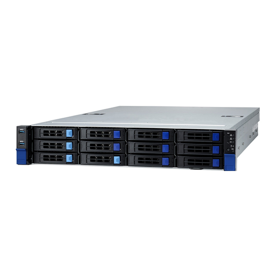
Page 24: About The Product
System Front View M1718T65-FPB Front Panel Board/ M1717T65-USB USB Board LAN1 LED ID Button LAN2 LED Power Button with green LED ID LED USB 3.1 Port Warning LED USB 3.1 Port HDD LED 3.5” /2.5” SSD/HDD/NVMe bays RESET Button http://www.tyan.com... - Page 25 Drive State Active LED (Green) Status LED (Red) Drive Present, No Active Solid on Drive Present with Active Blinking Don’t care Drive Failure Solid on Don’t care RAID Rebuild Blinking @4 Hz Don’t care Drive Locate Identifier Blinking @1 Hz http://www.tyan.com...
-
Page 26: System Rear View
LP card *1) Dedicated IPMI LAN PCIE Slot #03 (LAN3) Port (FH/HL card *1 or LP card*1) USB3.1 Ports PCIE Slot #02 (LP card *2) USB3.1 Ports PCIE Slot #01 (LP card *2) *LP card=Low profile card http://www.tyan.com... - Page 27 Right LED Link Green 10 Mbps Active Blinking Green Link Green Green 100 Mbps Active Blinking Green Green Link Green Amber 1000 Mbps(1Gps) Active Blinking Green Amber No Link NOTE: “Left” and “Right” are viewed from the rear panel. http://www.tyan.com...
- Page 28 2PSU + 2 AC cord are installed when system PS-ON. Solid on After system operation normally, one of PSU or AC cord be unplug. 1+1 PSU redundancy fail. Warning: All PSUs have to be AC-ON at the same time before you power on the system. http://www.tyan.com...
-
Page 29: System Top View
1.5.3 System Top View http://www.tyan.com... - Page 30 /M1296T65-BP12E-8 /M1298T65-BP12E-2 PSU1 HDD Backplane Board pre-installed (6) System fans PSU0 Memory Slot PCIE4.0 Slot x24 CPU Socket OCP 3.0 Slot Riser Card Bracket (M8252T75-R24-2F PCIE4.0 Slot x16 /M8252T75-R24-3F pre-installed) NOTE: The system is pre-installed with S8252GM2NE-2T system board http://www.tyan.com...
-
Page 31: Chassis Dimensions
1.5.4 Chassis Dimensions http://www.tyan.com... -
Page 32: Chapter 2: Setting Up
Caution! To avoid damaging the motherboard and associated components, use torque force within the range kgf/cm (6.09 lb/in) on each mounting screw for motherboard installation. Do not apply power to the board if it has been damaged. http://www.tyan.com... -
Page 33: Precautions
Components and electronic circuit boards can be damaged by discharges of static electricity. Working on a system that is connected to a power supply can be extremely dangerous. Follow the guidelines below to avoid damage to TS75-B8252 or injury to yourself. -
Page 34: Installing Motherboard Components
CPUs, memory modules and add on cards. 2.1.1 Removing the Chassis Cover Follow these instructions to remove TS75-B8252 chassis cover. 1. Remove the two screws securing the top cover to the chassis. Press firmly the locking latches. 2. Slide to lift the rear top cover up. -
Page 35: Installing The Cpu And Heatsink
Pull to release the rail frame. Then lift the rail frame to its fully open position. Remove the external cap from the rail frame. Using your thumbs and forefinger, remove the PnP cap by lifting it up vertically. http://www.tyan.com... - Page 36 During installation, observe the following: 1. Make sure to push the carrier frame with package towards the end of the rail frame until it clicks into place. 2. Do not drop the carrier frame or touch the package pad to avoid component damage. http://www.tyan.com...
- Page 37 7. Close the force frame. Then use a T20 Torx screwdriver to tighten the screws to secure the force frame in a sequential order (1 ->2->3). 8. Tighten the four screws in a diagonal sequence to secure the heat sink http://www.tyan.com...
-
Page 38: Installing The Memory
2. Align the memory module with the slot. When inserted properly, the memory slot locking levers lock automatically onto the indentations at the ends of the module. Follow the recommended memory population table to install the other memory modules. http://www.tyan.com... -
Page 39: Installing Hard Drives
2.1.4 Installing Hard Drives The TS75-B8252 supports twelve 3.5”/2.5” hot-swap HDD/SSDs. Installing 3.5” Hot-Swap Hard Drives Follow these instructions to install a 3.5” HDD. Warning!!! Always install the hard disk drive to the chassis after the chassis has been secured on the rack. - Page 40 Open the HDD tray and place the 3.5” hard disk drive into the HDD tray and lock the tray lever to secure HDD. Reinsert the HDD tray into the chassis. Push to secure the locking lever until it clicks into place. http://www.tyan.com...
- Page 41 http://www.tyan.com...
- Page 42 Follow these instructions to install a 2.5” HDD/SSD. Warning!!! Always install the hard disk drive to the chassis after the chassis has been secured on the rack. Press the locking lever latch and pull the locking lever open. Slide the HDD tray out. http://www.tyan.com...
- Page 43 Place the 2.5” HDD/SSD into the HDD tray and align the 2.5” HDD/SSD with its guide pins. Turn over the HDD tray and secure the HDD/SSD to the tray using 4 screws. http://www.tyan.com...
- Page 44 Reinsert the HDD tray into the chassis. Push to secure the locking lever until it clicks into place. http://www.tyan.com...
-
Page 45: Installing The Pci-E Card
2.1.5 Installing the PCI-E Card Follow these instructions to install the PCI-E card. There are four expansion slots in the chassis. Unscrew the riser card bracket NO.3. http://www.tyan.com... - Page 46 Unscrew the riser card bracket. 4. Remove the riser card bracket from the chassis. Follow the same procedures to remove the other riser card bracket from the chassis. http://www.tyan.com...
- Page 47 6. Unscrew to remove the dummy brackets. 7. Insert the PCI-E card into the riser card bracket and screw it firmly. Follow the same procedures to insert the card to the other side of the riser card bracket if necessary. http://www.tyan.com...
- Page 48 8. Reposition and screw the riser card bracket into the chassis. Screw the riser card bracket into the chassis. http://www.tyan.com...
- Page 49 http://www.tyan.com...
- Page 50 NO.One or four bracket Unscrew the riser card bracket NO.1 and NO. 4. Remove the riser card brackets for both sides from the chassis. Unscrew to remove the dummy brackets. http://www.tyan.com...
- Page 51 Insert the PCI-E card into the riser card bracket and screw it firmly. Reposition the riser card bracket to the chassis and secure the rotate screw firmly. Follow the same procedures to insert the card to the other side of the riser card bracket if necessary. http://www.tyan.com...
-
Page 52: Rack Mounting
19" rack. NOTE: Before mounting the TYAN TS75-B8252 chassis in a rack, ensure that all internal components have been installed and that the unit has been fully tested. However, to make the installation easier, we suggest that you remove all HDD trays before you insert the chassis into the rack. - Page 53 Install the Inner rail onto the chassis Align the inner sliding rail on the side of the server, and pull towards the arrow to secure the hooks Secure the inner rail to the chassis with 2pcs M4x4L screws on both side. http://www.tyan.com...
- Page 54 Pull the latch upward and remove the keyhole from standoff and slide inner rail forward to remove inner rail. Fix the Outer rail/bracket assembly to the frame Please according to the bracket type, and refer to the install/detach instruction. Secure the outer rails to the rack on each side. http://www.tyan.com...
- Page 55 Pull the middle rail fully extended in lock position, ensure ball bearing retainer is located at the front of the middle rail. Horizontally insert the chassis into middle-outer rails. When hit a stop, please pull/push the blue release tab on the inner rails. Tighten chassis with shipping screws. http://www.tyan.com...
-
Page 56: Removing The Server From Rack
2.2.2 Removing the Server from Rack 1. Loosen shipping screws to pull out chassis. 2. Pull the disconnect tab forward to remove chassis at the full extension position. 2. Push tab to slide the middle rail back. http://www.tyan.com... - Page 57 NOTE http://www.tyan.com...
-
Page 58: Chapter 3: Replacing Pre-Installed Components
This chapter explains how to replace the pre-installed components, including the Motherboard, M1717T65-FPB Front Panel Board, M1718T65-USB Board, M1297T65-BP12E-12 HDD Backplane, M8252T75-L16-1L M8252T75-L24-1F M8252T75-R24-2F/ M8252T75-R16-1L M8252T75-L16-2L/ M8252T75-R16-2L/ M8252T75-L24-2F M8252T75-R24-3F Riser cards, System fan and Power supply unit etc. Disassembly Flowchart The following flowchart outlines the disassembly procedure. http://www.tyan.com... -
Page 59: Removing The Cover
Removing the Cover Before replacing any parts you must remove the chassis cover first. Follow Chapter 2.1.1 to remove the cover of the TS75-B8252. Replacing Motherboard Components Follow these instructions to replace motherboard components, including the motherboard. 3.4.1 Replacing the Riser Card... - Page 60 Unscrew the riser card bracket. Remove the riser card brackets for both sides from the chassis. Unscrew the M8252T75-R24-1F riser card to replace with a new one. http://www.tyan.com...
- Page 61 Unscrew the M8252T75-R16-1L riser card to replace with a new one. Unscrew the M8252T75-L16-1L riser card to replace with a new one. Follow the steps described earlier in reverse to reinstall the riser card bracket. http://www.tyan.com...
-
Page 62: Pci-E Riser Cards Specification
12 layers Support (1) PCIE Gen4 slots Features PCIE x16 slot x1 M8252T75-R16-1F M8252T75-R16-1F Riser Card PCB Dimensions: 76.81mm x 270.04mm, thickness 1.6mm Layer: 12 layers Support (1) PCIE Gen4 slots Features PCIE x16 slot x1 http://www.tyan.com... - Page 63 PCIE x16 slot x1/ PCIE x8 slot x1 M8252T75-R16-2L M8252T75-R16-1F Riser Card PCB Dimensions: 76.81mm x 270.04mm, thickness 1.6mm Layer: 12 layers Support (2) PCIE Gen4 slots Features PCIE x16 slot x1/ PCIE x8 slot x1 http://www.tyan.com...
- Page 64 Support (1) PCIE Gen4 slots Features PCIE x16 slot x1 M8252T75-R24-2F M8252T75-R24-2F Riser Card PCB Dimensions: 76.81mm x 270.04mm, thickness 1.6mm Layer: 12 layers Support (2) PCIE Gen4 slots Features PCIE x16 slot x1/ PCIE x8 slot x1 http://www.tyan.com...
- Page 65 12 layers Support (3) PCIE Gen4 slots Features PCIE x16 slot x1/ PCIE x8 slot x2 NOTE: J4 is reserved for PCI-E device which need more power, the power could come from PSU Signal Signal J4 (PWR1) +12V http://www.tyan.com...
-
Page 66: Replacing The Front Panel Board
Replacing the Front Panel Board Follow these instructions to replace the M1718T65-FPB Front Panel Board. 1 Unscrew to release the Front Panel Board cover. 2 Remove the Front Panel Board cover. http://www.tyan.com... - Page 67 3 Unscrew the Front Panel Board to replace a new one. 4 Disconnect the Front Panel Board to replace a new one. 5 Follow the steps described earlier in reverse to reinstall the Front Panel Board. http://www.tyan.com...
-
Page 68: Front Panel Board Specifications
Form Factor Thickness: 1.6mm Layer: 4 layers power button with LED reset button ID button Specifications LED: LAN1 LED (green), LAN2 LED (green), ID LED (blue), HDD LED (green/Red), FAULT LED (Red/green/Blue), Power LED http://www.tyan.com... -
Page 69: Replacing The Usb Board
Replacing the USB Board Follow these instructions to replace the M1717T65-USB Board. 1 Unscrew to release the USB front cover. 2 Remove the USB front cover. http://www.tyan.com... - Page 70 3 Unscrew the USB Board. 4 Disconnect the USB Board to replace a new one. 5 Follow the steps described earlier in reverse to reinstall the USB Board. http://www.tyan.com...
-
Page 71: Usb Board Specifications
3.6.1 USB Board Specifications M1717T65-USB USB Board PCB Dimensions: 48.00*19.00*1.6mm Form Factor Thickness: 1.6mm Layer: 4 layers USB 3.0 Connector Specifications 5*2PIN input Connector http://www.tyan.com... -
Page 72: Replacing The System Fan
Replacing the System Fan Follow these instructions to replace the fan. Take out the fan from the chassis. Replace a new fan to the chassis. Reinstall a new fan to the chassis. http://www.tyan.com... -
Page 73: Replacing The Hdd Backplane Board
Disconnect all cables connected to the M1297T65-BP12E-12 HDD Backplane. Unscrew the HDD BP Board. Release the HDD Backplane from the hook. Follow the procedures described earlier to reinstall the HDD backplane board bracket into the chassis. http://www.tyan.com... -
Page 74: Hdd Backplane Board Features
Front View Rear View Form Factor Dimension: 422.4*29.8mm OCU Link Connector Input x 2 Specifications Mini SAS HD Connector Input x 3 Overview SGPIO Header x 4 SATA HDD or 8 SATA HDD x 12 + NVMe Output x 4 http://www.tyan.com... -
Page 75: Connector Definition
Reserved for AMD Platform SGPIO1 Reserved NOTE: The location, rebuilding, group raid and lamp function will be normally. When use LSI MR SAS 9361-8I Raid Card, the HDD backplane 3PHD_1 jumper need to be set to LSI RAID Mode. http://www.tyan.com... -
Page 76: Replacing The Power Supply
Follow these instructions to replace the power supply module in your system. Press the latch to pull the power supply out. After replacing a new power supply, press and hold the latch to push the power supply back into the chassis. http://www.tyan.com... -
Page 77: Disconnecting All Motherboard Cables
3.10 Disconnecting All Motherboard Cables Disconnect slim SAS cables connected to the motherboard. Disconnect slim SAS and power cables connected to the motherboard. http://www.tyan.com... -
Page 78: Removing The Motherboard
After removing all of the aforementioned cables, follow the instructions below to remove the motherboard from the chassis. Remove the air duct, processor and heatsink if installed. Remove three screws securing the bar from the chassis. Use a hex screwdriver and Phillips screwdriver to loosen screws. http://www.tyan.com... - Page 79 Unscrew the 13 screws with the Screwdriver. Carefully lift the motherboard from the chassis. http://www.tyan.com...
-
Page 80: Chapter 4: Installing Gpu Cards
T4 GPU card The TN75-B8252 supports four PCI-E Riser Card Brackets. Follow these instructions to install GPU card in your system. Unscrew the riser card bracket. Release the riser card bracket from the chassis. Remove the dummy bracket from the riser. http://www.tyan.com... - Page 81 Insert the tesla T4 GPU card and secure the tesla T4 GPU card to the riser. Reinstall the bracket to the chassis. Unscrew the riser card bracket. http://www.tyan.com...
- Page 82 Insert the tesla T4 GPU card and secure the tesla T4 GPU card to the riser. Reinstall the bracket to the chassis. http://www.tyan.com...
- Page 83 Secure GPU card onto the left and right riser card and secure the three screws and one rotary screw on both sides to the bracket. http://www.tyan.com...
-
Page 84: Installing The Nvidia Rtx6000 Gpu Card
Install the GPU card to the GPU bracket, and then secure the GPU card to the bracket with the four screws (2 screws for the front side of the bracket and 2 short screws for the rear side of the bracket). http://www.tyan.com... - Page 85 Connect the GPU power cable onto the GPU card to the bracket. http://www.tyan.com...
- Page 86 Reposition GPU card to the riser bracket and secure the three screws as in the image. Secure the two rotary screws. Reconnect the GPU power cables to the bracket. http://www.tyan.com...
-
Page 87: Chapter 5: Motherboard Information
Caution! To avoid damaging the motherboard and associated components, do not use torque force greater than 7kgf/cm (6.09 lb/in) on each mounting screw for motherboard installation. Do not apply power to the board if it has been damaged. http://www.tyan.com... -
Page 88: Board Image
Board Image S8252GM2NE-2T This picture is representative of the latest board revision available at the time of publishing. The board you receive may not look exactly like the above picture. http://www.tyan.com... -
Page 89: Block Diagram
Block Diagram S8252 Block Diagram http://www.tyan.com... -
Page 90: Motherboard Mechanical Drawing
Motherboard Mechanical Drawing http://www.tyan.com... -
Page 91: Board Parts, Jumpers And Connectors
The board you receive may not look exactly like the above diagram. The DIMM slot numbers shown above can be used as a reference when reviewing the DIMM population guidelines shown later in the manual. For the latest board revision, please visit our web site at http://www.tyan.com. http://www.tyan.com... - Page 92 10. X550 LAN Connector(X550_LAN1) 41. SYS_FAN_4 (SYS_FAN_4) 11. CPLD Flash FW(JTAG1) 42. SYS_FAN_3 (SYS_FAN_3) 43. Slim SAS CON(PCIE) (Slim SAS3) 12. TYAN Module Header (DBG_HD1) 13. IPMI LAN Connector(BMC_LAN) 44. Slim SAS CON(PCIE) (Slim SAS4) 45. SYS_FAN_2 (SYS_FAN_2) 14. USB3.0 x2 (USB3_2) 15.
- Page 93 SATA ACT LED (LED7) vii.BMC Heartbeat LED(BMC_HBLED) xvii. SATA ACT LED (LED8) Viii CPLD STATUS LED(LED2) xviii. SATA ACT LED (LED9) ix. CPLD RCR ERROR LED(LED1) Jumper Legend OPEN - Jumper OFF Without jumper cover CLOSED - Jumper ON With jumper cover http://www.tyan.com...
- Page 94 CPU1_FAN_1: CPU1 FAN Connector COM2/5 / COM1: COM1/2 Port Header Signal Signal FPIO_2: Front Panel Header Signal Signal PW_LED+ VDD3_DUAL IDLED+ PW_LED- IDLED- HD_LED+ HW_FAULT1- HD_LED- SYS_FAULT2- PW_SW# LAN0_LED LAN0_LED- RST_SW# SMBDATA SMBCLK IDLED_SW# INTRUDER# SYS_Air_Inlet LAN1_LED+ NMI_SW# LAN1_LED- http://www.tyan.com...
- Page 95 SSRX- SSRX+ USB DATA2- USB DATA2+ SSTX- SSTX+ SGPIO Header (P0_SATA_SGPIO0/ P0_SATA_SGPIO1/ P1_SATA_SGPIO1) Signal Signal SDIN DATA SDOUT SLOAD SCLOCK VDD3_DUAL DBG_HD1: TYAN Module Header Signal Signal P3V3 FRAME_N LAD0 LAD1 PLT_RST_N LAD2 LAD3 CLK_33M DBG_SERIRQ DBG_PRES_N VCC3_AUX TPM_ADDR_MB PCH_TPM_PP_EN...
- Page 96 TACH_SYS1 TACH_SYS6 TACH_SYS2 TACH_SYS7 TACH_SYS3 TACH_SYS8 TACH_SYS4 TACH_SYS9 TACH_SYS5 TACH_SYS10 PWM_SYS2 PWM_SYS1 TACH_SYS11 BMC_DAT3 TACH_SYS12 BMC_CLK3 VDD3_DUAL PWM_SYS3 VDD3_DUAL TACH_SYS13 TACH_CPU1 TACH_SYS14 TACH_CPU0 PWM_SYS4 PWM_SYS5 PWM_CPU0 J20/J25/J26/J27: 7 Pin Header for hot plug Signal Signal VDD_33_Dual HP_CLK HP_DATA HP-ALERT http://www.tyan.com...
- Page 97 P12_HDD2 P12_HDD2 PE_PW3: 8-pin Power Connector to HDD BP Signal Signal P12_HDD3 P12_HDD3 P12_HDD3 P12_HDD3 NOTE: The 8-pin GPU power connector can support up to 20A. PE_PW4: 8-pin Power Connector to GPU Card Signal Signal P12_GPU1 P12_GPU1 P12_GPU1 P12_GPU1 http://www.tyan.com...
- Page 98 PE_PW5: 8-pin Power Connector to GPU Card Signal Signal P12_GPU2 P12_GPU2 P12_GPU2 P12_GPU2 HD_PW1/HD_PW2: 8-pin Power Connector to GPU Card Signal Signal P12V_HD P12V_HD P12V_HD P12V_HD HD_PW3: 8-pin Power Connector to GPU Card Signal Signal VDD_12_PSU VDD_5_RUN SHD_PW4/ SHD_PW5/ SHD_PW6/ SHD_PW7/SHD_PW8 Signal Signal VDD_12_PSU VDD_5_RUN http://www.tyan.com...
-
Page 99: Thermal Interface Material
CPU lid (applying too much will actually reduce the cooling). NOTE: Always check with the manufacturer of the heat sink & processor to ensure that the thermal interface material is compatible with the processor and meets the manufacturer’s warranty requirements. http://www.tyan.com... -
Page 100: Tips On Installing Motherboard In Chassis
Be especially careful to look for extra stand-offs. If there are any stand-offs present that are not aligned with a mounting hole on the motherboard, it will likely short components on the back of the motherboard when installed. This will cause malfunction and/or damage to your motherboard. http://www.tyan.com... - Page 101 Some chassis include plastic studs instead of metal. Although the plastic studs are usable, MITAC recommends using metal studs with screws that will fasten the motherboard more securely in place. Below is a chart detailing what the most common motherboard studs look like and how they should be installed. http://www.tyan.com...
-
Page 102: Installing The Memory
Installing the Memory Before installing memory, ensure that the memory you have is compatible with the motherboard and processor. Check the TYAN Web site at http://www.tyan.com details of the type of memory recommended for your motherboard. (16+16) DIMM slots support /(L)RDDR4 up to 3200 w/ ECC (1.2V) ... - Page 103 Populating NVDIMMs NVDIMMs are identical only per channel pair. D-R,LR, or 3DS DIMM type Populating NVDIMMs with capacity-2x D RDIMMs or capacity LRDIMMs Table2.DIMM Interleaving Guidelines Slots DIMMs DIMM Frequency(MT/s) Populated 1.2V 2667 2667 2667 2400 2133 2133 2133 http://www.tyan.com...
- Page 104 √ √ P1_D3_UMC0_CH_E0 √ √ √ √ √ √ √ P1_D3_UMC0_CH_E1 √ P1_D3_UMC1_CH_F0 √ √ √ √ √ P1_D3_UMC1_CH_F1 √ √ √ P1_D2_UMC1_CH_G0 √ √ √ √ √ √ √ P1_D2_UMC1_CH_G1 √ P1_D2_UMC0_CH_H0 √ √ √ √ √ P1_D2_UMC0_CH_H1 http://www.tyan.com...
-
Page 105: Finishing Up
In the rare circumstance that you have experienced difficulty, you can find help by asking your vendor for assistance. If they are not available for assistance, please find setup information and documentation online at our website or by calling your vendor’s support line. http://www.tyan.com... - Page 106 NOTE http://www.tyan.com...
-
Page 107: Chapter 6: Bios Setup
Select the previous value/setting of the field <+> Select the next value/setting of the field <F8> Load Fail Safe default configuration values of the menu <F3> Load the Optimal default configuration values of the menu <F4> Save and exit <Enter> Execute command or select submenu http://www.tyan.com... - Page 108 BIOS menus are continually changing due to continual BIOS updates over the product lifespan of the motherboard. The BIOS menus provided are current as of the date when this manual was written. Please visit TYAN’s website at http://www.tyan.com for information on BIOS updates available for this specific motherboard.
-
Page 109: Main Menu
It displays Platform information. Memory Information This displays the total memory size. System Language Choose the system default language. System Date Set the Date. Use Tab to switch between Date elements. Default Ranges: Year: 2005-2099 Months: 1-12 Days: dependent on month http://www.tyan.com... - Page 110 System Time Set the Time. Use Tab to switch between Time elements. http://www.tyan.com...
-
Page 111: Advanced Menu
PCIE Slot Configuration Onboard PCIE Slot Configuraion Trusted Computing Trusted Computing Setting Hardware Health Configuration Hardware health Configuration S5 RTC Wake Settings S5 RTC Wake Settings Serial Port Console Redirection Serial Port Console Redirection CPU Configuration CPU Configuration Parameters http://www.tyan.com... - Page 112 NVMe Device Options Settings SATA Configuration SATA Devices Information NVDIMM Force Self Refresh NVDIMM Force Self Refresh Configuration Network Stack Configuration Network Stack Settings AMD Mem Configuration Status To display memory configuration (initialized by ABL) status iSCSI Configuration Configure the iSCSI parameters. http://www.tyan.com...
- Page 113 Disabled / Enabled Active Video Select between onboard or external VGA support. Onboard Offboard Onboard LAN Enable/Disable Onboard LAN Devices. Disabled Enabled NMI Button Enable or Disable NMI button Disabled Enabled Clock Spread Spectrum Enable/Disable CG1_PLL Spread Spectrum Disabled Enabled http://www.tyan.com...
- Page 114 J5-J6 SATA or NVMe link Select Select link header function as Nvme or SATA function NVMe / SATA Global PCIe ASPM Support Control all the PCIe devices ASPM Support Disabled / L0s Entry / L1 Entry / L0s And L1 Entry http://www.tyan.com...
- Page 115 Auto / Gen 1 (2.5 GT/s) / Gen 2 (5 GT/s) / Gen 3 (8 GT/s) Riser 2 Down Slot Link Speed OnBoard PCIE Slot Link Speed Configuration Auto / Gen 1 (2.5 GT/s) / Gen 2 (5 GT/s) / Gen 3 (8 GT/s) http://www.tyan.com...
- Page 116 6.3.4 Trusted Computing Security Device Support Enable or disable BIOS support for security device. O.S. will not show Security device. O.S. will not show Security Device. TCG EFI protocol and INT1A interface will not be available. Enabled / Disabled http://www.tyan.com...
- Page 117 On / Off NOTE: When Auto Fan Control was set to [Manual] PWM Minimal Duty Cycle And BMC Alert Beep Item will appear. PWM Minimal Duty Cycle PWM Minimal Duty Cycle BMC Alert Beep Enable/Disable BMC Alert Beep On / Off http://www.tyan.com...
- Page 118 1 / 1+1 / 2+1 6.3.5.1 Sensor Data Register Monitoring When you enter the Sensor Data Register Monitoring submenu, you will see the following dialog window pop out. Please wait 8~10 seconds. NOTE 1: SDR can not be modified. Read only. http://www.tyan.com...
- Page 119 http://www.tyan.com...
- Page 120 http://www.tyan.com...
- Page 121 Select 0-23. For example enter 3 for 3am and 15 for 3pm. Wake up minute Select 0-59 for Minute. Wake up second Select 0-59 for Second. When Wake system from S5 is set to [Dynamic Time] Wake up Minute increase 1-5. http://www.tyan.com...
- Page 122 NOTE: Console Redirection Settings menu only appear when Console Redirection was set to [Enabled]. Legacy Console Redirection Legacy Console Redirection Settings Serial Port for Out-Of-Band Management/Windows Emergency Services (EMS) Console Redirection Console redirection enable or disable. Disabled / Enabled http://www.tyan.com...
- Page 123 0 if the num of 1’s in the data bits is even. Odd: parity bit is 0 if the num of 1’s in the data bits is odd. Mark: parity bit is always 1. Space: parity bit is always 0. Mark and Space parity do not allow for error detection. None / Even / Odd / Mark / Space http://www.tyan.com...
- Page 124 Disabled / Enabled Legacy OS Redirection Resolution On Legacy OS, the number of rows and columns supported redirection. 80x24 / 80x25 Putty KeyPad Select FunctionKey and KeyPad on Putty. VT100 / LINUX / XTERMR6 / SCO / ESCN / VT400 http://www.tyan.com...
- Page 125 0 if the num of 1’s in the data bits is even. Odd: parity bit is 0 if the num of 1’s in the data bits is odd. Mark: parity bit is always 1. Space: parity bit is always 0. Mark and Space parity do not allow for error detection. None / Even / Odd / Mark / Space http://www.tyan.com...
- Page 126 With this mode enabled only text will be sent. This is to capture Terminal data. Disabled / Enabled Resolution 100x31 Enable or disable extended terminal resolution. Disabled / Enabled Putty KeyPad Select FunctionKey and KeyPad on Putty. VT100 / LINUX / XTERMR6 / SCO / ESCN / VT400 http://www.tyan.com...
- Page 127 When Bootloader is selected, then Legacy Console Redirection is disabled before booting to legacy OS. When Always Enable is selected, then Legacy Console Redirection is enabled for Legacy OS. Default setting for this option is set to Always Enable. Always Enable / BootLoader http://www.tyan.com...
- Page 128 VT-UTF8 / VT100 / VT100+ / ANSI Bits per Second Select serial port transmission speed. The speed must be matched on the other side. Long or noisy lines may require lower speeds. 115200 / 9600 / 19200 / 38400 / 57600 http://www.tyan.com...
- Page 129 None / Hardware RTS/CTS Data Bits / Parity / Stop Bits Read only. 6.3.8 CPU Configuration submenu SVM Mode Enable/disable CPU Virtualization Disabled / Enabled SMEE Control secure memory encryption enable Disabled / Enabled http://www.tyan.com...
- Page 130 CPU 0 Information View Information related to CPU 0 CPU 1 Information View Information related to CPU 1 6.3.8.1 CPU0 Information http://www.tyan.com...
- Page 131 6.3.8.2 CPU1 Information Read only. http://www.tyan.com...
- Page 132 6.3.9 AST2500 Super IO Configuration http://www.tyan.com...
- Page 133 / IO=3F8h, IRQ=3, 4, 5, 6, 7, 9, 10, 11, 12;DMA; / IO=2F8h; IRQ=3, 4, 5, 6, 7, 9, 10, 11, 12;DMA; / IO=3E8h, IRQ=3, 4, 5, 6, 7, 9, 10, 11, 12;DMA; / IO=2E8h, IRQ=3, 4, 5, 6, 7, 9, 10, 11, 12;DMA; http://www.tyan.com...
- Page 134 / IO=3F8h, IRQ=3, 4, 5, 6, 7, 9, 10, 11, 12;DMA; / IO=2F8h; IRQ=3, 4, 5, 6, 7, 9, 10, 11, 12;DMA; / IO=3E8h, IRQ=3, 4, 5, 6, 7, 9, 10, 11, 12;DMA; / IO=2E8h, IRQ=3, 4, 5, 6, 7, 9, 10, 11, 12;DMA; http://www.tyan.com...
- Page 135 If system has SR-IOV capable PCIe devices, this option Enables or Disables Single Root IO virtualization Support Enabled / Disabled BME DMA Mitigation Re-enable Bus Master Attribute disabled during Pci enumeration for PCI Bridges after SMM Locked Enabled / Disabled PCI Express Settings Change PCI Express Devices Settings. http://www.tyan.com...
- Page 136 Set Maximum Read Request Size of PCI Express Device or allow system BIOS to select the value Auto 128 Bytes / 256 Bytes / 512 Bytes / 1024 Bytes / 2048 Bytes / 4096 Bytes MMIO Limit Address MMIO Limit Address 512 G / 1T / 2T / 4T / 255T http://www.tyan.com...
- Page 137 PCI Device http://www.tyan.com...
- Page 138 USB Mass Storage Driver Support Enable/Disable USB Mass Storage Driver Support Enabled / Disabled Port 60/64 Emulation Enables I/O port 60h/64h emulation support. This should be enabled for the complete USB keyboard legacy support for non-USB aware OSes. Enabled / Disabled http://www.tyan.com...
- Page 139 Controller. AUTO uses default value: for a Root port it is 100 ms, for a Hub port the delay is taken from Hub descriptor. Auto / Manual 6.3.12 CSM Configuration CSM support Enable/Disable CSM Support Enabled / Disabled Option ROM Messages Set display mode for Option ROM Force BIOS / Keep Current http://www.tyan.com...
- Page 140 Do not launch / UEFI / legacy Video Controls the execution of UEFI and legacy PXE OpROM Do not launch / UEFI / legacy Other PCI devices Determines OpRom execution policy for devices other than network, storage, or video legacy / UEFI 6.3.13 NVMe Configuration http://www.tyan.com...
- Page 141 6.3.14 SATA Configuration http://www.tyan.com...
- Page 142 6.3.15 NVDIMM Force Self Refresh Configuration NVDIMM Force Self Refresh Asset NVDIMM Save on cold reset and warm reset Enabled / Disabled Asset NVDIMM Save on Shutdown Asset NVDIMM Save on Shutdown Enabled / Disabled http://www.tyan.com...
- Page 143 6.3.16 Network Stack Configuration Network Stack Enable/Disable UEFI Network Stack Enabled / Disabled http://www.tyan.com...
- Page 144 6.3.17 AMD Mem Configuration Status Socket 0 Socket-specific memory configuration status Socket 1 Socket-specific memory configuration status http://www.tyan.com...
- Page 145 6.3.17.1 Socket Configuration Status Channel 0/1/2/3/4/5/6/7 Channel-specific memory configuration status http://www.tyan.com...
- Page 146 6.3.17.1.1 Channel 0/1/2/3/4/5/6/7 Configuration Status http://www.tyan.com...
- Page 147 6.3.18 iSCSI Configuration http://www.tyan.com...
-
Page 148: Chipset Menu
Enable or Disable Non uniform Memory Access (NUMA). Enabled / Disabled PCIe Link Training Type PCIe Link training in 1 or 2 steps. 1 Step / 2 Step PCIe Compliance Mode PCIe Link Compliance Mode Off / On North Bridge North Bridge Patameters http://www.tyan.com... - Page 149 6.4.1 North Bridge Configuration Socket 0 Information View Information related to socket 0 Socket 1 Information View Information related to Socket 1 http://www.tyan.com...
- Page 150 6.4.1.1 Socket 0 Information http://www.tyan.com...
- Page 151 6.4.1.2 Socket 1 Information http://www.tyan.com...
-
Page 152: Amd Configuration
AMD Configuration http://www.tyan.com... - Page 153 Enable/disable PFEH, cloak individual banks, and mask deferred error interrupt from each bank. Enabled / Disabled / Auto Core Performance Boost Disable CPB Disabled / Auto Global C-state Control Controls IO based C-state generation and DF C-states. Enabled / Disabled / Auto http://www.tyan.com...
- Page 154 PDM function as expected. breakpoint redirect capability compromised silver workaround: DbReq, PDM, and breakpoint redirect function as expected, SCAN capability compromised Auto / No workaround / Bronze Workaround / Silver Workaround PPIN Opt- in Turn on PPIN feature. Disabled / Enabled / Auto http://www.tyan.com...
- Page 155 6.5.2 Performance Options Custom Core Pstates CCD/Core/Thread Enablement http://www.tyan.com...
- Page 156 6.5.2.1 Custom Core Pstates Options http://www.tyan.com...
- Page 157 WARNING – DAMAGE CAUSED BY USE OF YOUR AMD PROCESSOR OUTSIDE OF SPECIFICATION OR IN EXCESS OF FACTORY SETTINGS ARE NOT COVERED UNDER YOUR AMD PRODUCT WARRANTY AND MAY NOT BE COVERED BY YOUR SYSTEM Disabled / CUSTOM / AUTO http://www.tyan.com...
- Page 158 WARNING – DAMAGE CAUSED BY USE OF YOUR AMD PROCESSOR OUTSIDE OF SPECIFICATION OR IN EXCESS OF FACTORY SETTINGS ARE NOT COVERED UNDER YOUR AMD PRODUCT WARRANTY AND MAY NOT BE COVERED BY YOUR SYSTEM Disabled / CUSTOM / AUTO 6.5.2.2 CCD/Core/ Thread Enablement http://www.tyan.com...
- Page 159 Auto /TWO (1+1) / FOUR (2+2) / SIX (3+3) SMT Control Can be used to disable symmetric multithreading. To re-enable SMT, a POWER CYCLE is needed after selecting the ‘Auto’ option. WARNING - S3 is NOT SUPPORTED on systems where SMT is disabled. Diabled / Auto http://www.tyan.com...
- Page 160 6.5.2.1.3 Prefetcher settings L1 Stream HW Prefetcher Option to Enable / Disable L1 Stream HW Prefetcher Disable / Enable / Auto L2 Stream HW Prefetcher Option to Enable / Disable L1 Stream HW Prefetcher Disable / Enable / Auto http://www.tyan.com...
- Page 161 6.5.2.1.4 Core Watchdog Core Watchdog Timer Enable Enable or disable CPU Watchdog Timer Disable / Enable / Auto http://www.tyan.com...
- Page 162 Control whether or not the CC6 save/restore memory is encrypted System probe filter Controls whether or not the probe filter is enabled. Has no effect on parts where the probe filter is fuse disabled. Disabled / Enabled / Auto http://www.tyan.com...
- Page 163 Provide a value that is the number of hours to scrub memory. Disabled / 1hour / 4 hours / 8 hours / 16 hours / 24 hours / 48 hours / Auto Poison scrubber control Control DF:: RedirScrubCtrl[RedirScrubMode[1]] Disabled / Enabled / Auto http://www.tyan.com...
- Page 164 Disabled / Enabled / Auto 5.5.3.2 Memory Options NUMA nodes per socket Specifies the number of desired NUMA nodes per socket. Zero will attempt to interleave the two sockets together. NPS0 / NPS1 / NPS2 / NPS4 / Auto http://www.tyan.com...
- Page 165 DRAM or distributed. Note that distributed requires memory on all dies. Note that it will always be at the top of DRAM if some dies don’t have memory regardless of this option’s setting. Distributed / Consolidated / Auto http://www.tyan.com...
- Page 166 Disabled / Enabled / Auto ACPI SLIT Distance Control Determines how the SLIT distances are declared. Manual / Auto ACPI SLIT remote relative distance Set the remote socket distance for 2P systems as near (2.8) or far (3.2). Near / Far / Auto http://www.tyan.com...
- Page 167 10.667Gbps / 13Gbps / 16Gbps / 18Gbps / Auto 3-link xGMI max speed 10.667Gbps / 13Gbps / 16Gbps / 18Gbps / Auto xGMI TXEQ Mode Select XGMI TXEQ/RX vetting Mode TXEQ_Disabled / TXEQ_Lane / TXEQ_link / TXEQ_RX_Vet / Auto http://www.tyan.com...
- Page 168 6.5.3.5 UMC Common Options http://www.tyan.com...
- Page 169 6.5.3.6 DDR4 Common Options http://www.tyan.com...
- Page 170 6.5.3.6.1 DRAM Timing Configuration http://www.tyan.com...
- Page 171 6.5.3.6.1.1 I Accept Configuration Overclock Memory Overclock settings Auto / Enabled http://www.tyan.com...
- Page 172 6.5.3.6.2 DRAM Controller Configuration Cmd2T Select between 1T and 2T mode on ADDR/CMD 1T / 2T / Auto Gear Down Mode Disabled / Enabled / Auto http://www.tyan.com...
- Page 173 CAD Bus Configuration CAD Bus Timing User Controls Setup time on CAD bus signals to Auto or Manual Auto / Manual CAD Bus Drive Strength User Control Drive Strength on CAP bus signals to Auto or Manual Auto / Manual http://www.tyan.com...
- Page 174 6.5.3.6.4 Data Bus Configuration Data Bus Configuration User Control Specify the mode for drive strength to Auto or Manual Auto / Manual http://www.tyan.com...
- Page 175 Enable or Disable DRAM Post Package Repair Disable / Enable RCD Parity Disabled / Enabled / Auto DRAM Address Command Parity Retry UMC_CH:: RecCtrl[RecEn] [0] and UMC_CH:: RecCtrl[MaxParRply] Disabled / Enabled / Auto Write CRC Enable Disabled / Enabled / Auto http://www.tyan.com...
- Page 176 DRAM ECC Enable Use this option to enable / disable DRAM ECC. Auto will set ECC to enable. Disabled / Enabled / Auto DRAM UECC Retry Use this option to enable / disable DRAM UECC Retry Disabled / Enabled / Auto http://www.tyan.com...
- Page 177 6.5.3.8 Security TSME Transparent SME: AddrTweakEn=1; ForceEncrEn =1;DataEncrEn=0 Disabled / Enabled / Auto Data Scramble Data scrambling: DataScrambleEn Disabled / Enabled / Auto http://www.tyan.com...
- Page 178 Disabled / Enabled / Auto BankGroupSwapAlt Disabled / Enabled / Auto Address Hash Bank Enable or disable bank address hashing Disabled / Enabled / Auto Address Hash CS Enable or disable CS address hashing Disabled / Enabled / Auto http://www.tyan.com...
- Page 179 Disabled / Enabled / Auto SPD Read Optimization Enable or disable SPD Read Optimization, Enabled – SPD reads are skipped for Reserved fields and most of upper 256 Bytes, Disabled – read all 512 SPD Bytes Disabled / Enabled / Auto 6.5.3.10 NVDIMM http://www.tyan.com...
- Page 180 Interface Mode / Data Eye Mode / Both / Auto MBIST Aggressors Enable or disable MBIST Aggressor test Disabled / Enabled / Auto MBIST Per Bit Slave Die Reporting Reports 2D Data Eye Results in ABL Log for each DQ. Chipselect, and Channel Disabled / Enabled / Auto http://www.tyan.com...
- Page 181 The default is set to disabled. Disabled / 1 Aggressor channel / 3 Aggressor channels / 7 Aggressor Channels Aggressor Static Lane Control This option, if enabled, will control the Aggressor Static Lane Controls. Disabled / Enabled Target Static Lane Control Disabled / Enabled http://www.tyan.com...
- Page 182 This option determines the step size for write Data Eye voltage sweep, Supported options are 1,2 and 4 1 / 2 / 4 Write Timing Sweep Step Size This options supports step size for write Data Eye. Support options are 1,2 and 4 1 / 2 / 4 http://www.tyan.com...
- Page 183 PCIe ARI Support Enable Alternative Routing-ID Interpretation Disabled / Enabled / Auto PCIe Ten Bit Tag Support Enables PCIe ten bit tags for supported devices. Auto = Disabled Disabled / Enabled / Auto HD Audio Enable Disabled / Enabled / Auto http://www.tyan.com...
- Page 184 Presence Detect Select mode Control the Presence Detect select mode OR / AND / Auto Preferred IO Preferred IO Select Type Manual: Bus Number manuality Auto: Default Auto / Manual Loopback Mode Enable/Disable Pcie Loopback Mode Disabled / Enabled / Auto http://www.tyan.com...
- Page 185 Manual = User can set customized TDP*** TDP is used to define the RC thermal model only *** Manual / Auto CLDO_VDDP Control Manual = User can set customized CLD0_VDDP voltage Manual / Auto EfficiencyModeEn 0= use performance optimized CCLK DPM settings 1= use power efficiency optimized CCLK DPM settings Auto / Enabled http://www.tyan.com...
- Page 186 DF Cstates Enable = Enable DF C-states Disable = Disable DF C-states Disabled / Enabled / Auto CPPC FEATURE_CPPC_MASK Disabled / Enabled / Auto BoostFmaxEn Auto = Use the default Fmax Manual = User can set the boost Fmax http://www.tyan.com...
- Page 187 6.5.3.15 Fan Control Configuration Fan Control Auto = Use the default fan table Manual = User can set customized fan table Manual / Auto http://www.tyan.com...
- Page 188 NBIO SyncFlood Generation This value may be used to mask SyncFlood caused by NBIO RAS options. When set to TRUE SyncFlood from NBIO is masked, when set to FALSE NBIO is capable of generating SynFlood. Disabled / Enabled / Auto http://www.tyan.com...
- Page 189 A value of 2 provides for Firmware First handling of errors through generation of a system management interrupt (SMI). Firmware First / OS First / MCA / Auto Edpc Control (0) Disabled; (1) Enabled; (3) Auto Disabled / Enabled / Auto NBIO Poison Consumption Disabled / Enabled / Auto http://www.tyan.com...
- Page 190 When ‘Sync Flood on PCIe Fatal Error’ is True, PcdAmdPcieSyncFloodOnFatal should be set to True. When ‘Sync Flood on PCIe Fatal Error’ is False, PcdAmdPcieSyncFloodOnFatal should be set to False. When’ Sync Flood on PCie Fatal error’ is Auto, PcdAmd PcieSyncFloodOnFatal 6.5.4 FCH Common Options http://www.tyan.com...
- Page 191 Sata Disable AHCI Prefetch Function Disable or enable Sata Disabled AHCI Prefetch Function Disabled / Enabled / Auto Aggressive SATA Device Sleep Port 0 Disabled / Enabled / Auto Aggressive SATA Device Sleep Port 1 Disabled / Enabled / Auto http://www.tyan.com...
- Page 192 6.5.4.1.1 SATA Controller Options http://www.tyan.com...
- Page 193 Disabled / Enabled / Auto Sata3 Enable Enable or Disable Sata3.Each IOD has 4 Sata Controllers. Disabled / Enabled / Auto Sata4 (Socket1)Enable Enable or Disable Sata4 on Socket 1 (IOD1).. Each IOD has 4 Sata Controllers. Disabled / Enabled / Auto http://www.tyan.com...
- Page 194 Enable or Disable Sata6 on Socket 1 (IOD1).. Each IOD has 4 Sata Controllers. Disabled / Enabled / Auto Sata7 (Socket1)Enable Enable or Disable Sata7 on Socket 1 (IOD1).. Each IOD has 4 Sata Controllers. Disabled / Enabled / Auto http://www.tyan.com...
- Page 195 6.5.4.1.1.2 SATA Controller eSATA http://www.tyan.com...
- Page 196 6.5.4.1.1.3 SATA Controller DevSlp http://www.tyan.com...
- Page 197 6.5.4.1.1.3.1 SATA Controller DevSlp Socket1 DevSlp0 Enable Only Sata0 on each IOD/socket support DevSlp Disabled / Enabled / Auto Socket1 DevSlp1 Enable Only Sata0 on each IOD/socket support DevSlp Disabled / Enabled / Auto http://www.tyan.com...
- Page 198 Sata2 SGPIO Enable or Disable SataSgpio on Sata2 Disabled / Enabled / Auto Sata3 SGPIO Enable or Disable SataSgpio on Sata3 Disabled / Enabled / Auto Sata4 SGPIO Enable or Disable SataSgpio on Sata (Socket1) Disabled / Enabled / Auto http://www.tyan.com...
- Page 199 Enable or Disable SataSgpio on Sata5 Disabled / Enabled / Auto Sata7 SGPIO Enable or Disable SataSgpio on Sata7(Socket7) Disabled / Enabled / Auto 6.5.4.1.2 USB Configuration Options XHCI Controller0 enable Enable or disable USB3 controller Disabled / Enabled / Auto http://www.tyan.com...
- Page 200 XHCI Controller1 enable Enable or disable USB3 controller. Disabled / Enabled / Auto USB ecc SMI Enable Enabled / Off / Auto http://www.tyan.com...
- Page 201 6.5.4.1.2.1 MCM USB enable Options XHCI2 enable (Socket1) Enable or disable USB3 controller. Disabled / Enabled / Auto XHCI3 enable (Socket1) Enable or disable USB3 controller. Disabled / Enabled / Auto http://www.tyan.com...
- Page 202 6.5.4.1.2.2 SD Dump Options SD Configuration Mode Select SD Mode SD Dump disabled / SD Dump enabled http://www.tyan.com...
- Page 203 6.5.4.1.2.3 Ac Power Loss Options Ac Loss Control Select Ac Loss Control Method Always Off / Always On / Reserved / Previous / Auto http://www.tyan.com...
- Page 204 I2C 1 Enable Disabled / Enabled / Auto I2C 2 Enable Disabled / Enabled / Auto I2C 3 Enable Disabled / Enabled / Auto I2C 4 Enable Disabled / Enabled / Auto I2C 5 Enable Disabled / Enabled / Auto http://www.tyan.com...
- Page 205 Uart 1 Enable Uart 1 has no HW FC if Uart 3 is enabled Disabled / Enabled / Auto Uart 2 Enable (no HW FC) Disabled / Enabled / Auto Uart 3 Enable (no HW FC) Disabled / Enabled / Auto http://www.tyan.com...
- Page 206 6.5.4.1.2.6 ESPI Configuration Options ESPI Enable Disabled / Enabled / Auto http://www.tyan.com...
- Page 207 High Speed SDR / eMMC High Speed DDR / eMMC HS200 / eMMC HS400 / eMMC HS300 / Auto Driver Type Bios will select MS driver for SD selections. AMD eMMC Driver / MS Driver / Auto D3 Cold Support Disabled / Enabled / Auto eMMC Boot Disabled / Enabled / Auto http://www.tyan.com...
- Page 208 6.5.4.1.2.8 FCH RAS Options Alink RAS Support Disabled / Enabled / Auto Reset after sync flood Enable AB to forward downstream sync-flood message to system controller. Disabled / Enabled / Auto http://www.tyan.com...
- Page 209 6.5.4.1.8 NTB Common Options NTB Enable Enabled / Auto http://www.tyan.com...
- Page 210 Auto: Keep default behavior Disabled / Enabled / Auto ABL PMU message Control To control the total number of PMU debug messages. Several major controls are listed below: 1.Detailed debug messages(e.g.Eye delays) 2.Coarse debug message (e.g.rank information) 3.Stage completion http://www.tyan.com...
- Page 211 BMC response for specified time out. BMC starts at the same time when BIOS starts during AC power ON. It takes around 30 seconds to initialize Host to BMC interfaces. Disabled / Enabled FRB-2 Timer Enable or Disable FRB-2 timer (POST timer) Disabled / Enabled http://www.tyan.com...
- Page 212 Do Nothing / Reset / Power Down / Power Cycle BMC Logo Enable or disable BMC logo Disabled / Enabled System Event Log Press<Enter> to change the SEL event log configuration. BMC network configuration Configure BMC network parameters BMC Warm Reset Press<Enter> to do warm Reset BMC http://www.tyan.com...
- Page 213 Do Nothing / Erase Immediately / Delete Oldest Record Log EFI Status Codes Disable the logging of EFI Status Codes or log only error code or only progress code or both. Both / Disabled / Error Code / Progress Code http://www.tyan.com...
- Page 214 6.5.5.2 BMC Network Configuration http://www.tyan.com...
- Page 215 Enable or Disable LAN1 IPV6 Support Enabled / Disabled Configuration Address source Select to configure LAN channel parameters statically or dynamically (by BIOS or BMC). Unspecified option will not modify any BMC network parameters during BIOS phase Unspecified / Static / DynamicBmcDhcp http://www.tyan.com...
-
Page 216: Security
Set user password in the Create New Password window. After you key in the password, the Confirm New Password window will pop out to ask for confirmation. Security Frozen Mode Enable or disable HDD security freeze lock. Disable to support secure erase function. Disabled / Enabled http://www.tyan.com... - Page 217 Restore Factory Keys Force System to User Mode. Install factory default Secure Boot Key databases. Reset To Setup Mode Delete all Secure Boot Key database from NVRAM Key Management Enables expert users to modify Secure Boot Policy variables without full authentication http://www.tyan.com...
- Page 218 Copy NVRAM content of Secure Boot variables to files in a root folder on a file system device Enroll Efi Image Allow the image to run in Secure Boot mode. Enroll SHA256 hash of the binary into Autorized Signature Database (db) http://www.tyan.com...
- Page 219 (DER encoded) c)EFI_CERT_RSA2048(bin) d)EFI_CERT_SHA256,384,512 2.Autheticated UEFI Variable 3.EFI PE/COFF Image (SHA256) Key Source: Default, External, Mixed, Test Save to File / set New / Append / Erase Forbidden Signatures Enroll Factory Defaults or load certificates from a file: http://www.tyan.com...
- Page 220 OsRecovery Signatures Enroll Factory Defaults or load certificates from a file: 1. Public Key Certificate in: a)EFI_signature_LIST b)EFI_CERT_X509 (DER encoded) c)EFI_CERT_RSA2048(bin) d)EFI_CERT_SHA256,384,512 2.Autheticated UEFI Variable 3.EFI PE/COFF Image (SHA256) Key Source: Default, External, Mixed, Test Set New / Append http://www.tyan.com...
-
Page 221: Boot
Enable or disable Quiet Boot option. Disabled / Enabled Endless Boot Enable or disable Endless Boot. Disabled / Enabled Wait For “ESC” If Error Enable or disable wait ‘ESC’ key Function. When chassis intrusion CMOS clear or BMC not Response. Disabled / Enabled http://www.tyan.com... - Page 222 Boot Option #3 Select the first boot device. Device Name / Device Name / Disabled 6.7.1 Delete Boot Option Configuration Delete Boot Option Remove an EFI boot option from the boot order Select one to Delete / Device Name http://www.tyan.com...
- Page 223 6.7.2 Hard Drive BBS Priorities Configuration Boot Option #1 Device Name / Disabled http://www.tyan.com...
- Page 224 6.7.3 Network Device BBS Priorities Configuration Boot Option #1 Sets the system boot order. Device Name / Device Name / Disabled Boot Option #2 Sets the system boot order. Device Name / Device Name / Disabled http://www.tyan.com...
-
Page 225: Save & Exit
Save Changes Save changes done so far to any of the setup options. Discard Changes Discard changes done so far to any of the setup options. Restore Defaults Restore/Load Default values for all the setup options. Save as User Defaults http://www.tyan.com... - Page 226 Save the changes done so far as User Defaults. Restore User Defaults Restore the User Defaults to all the setup options. http://www.tyan.com...
-
Page 227: Appendix I: Installing Io Plate For Ocp Card
Follow these instructions to install the IO Plate for OCP Card. Here shows how to install the OCP 3.0 card 1. Use a screwdriver to remove the dummy cover for the OCP card slot. 7. Insert the OCP 3.0 card into the OCP slot http://www.tyan.com... - Page 228 8. Secure the OCP 3.0 card to the chassis 8. The OCP 3.0 card to the chassis has been completed. http://www.tyan.com...
-
Page 229: Appendix Ii: Cable Connection Tables
SLIMSAS J56 Not connected Power Cable PE_PW4 Power Cable PE_PW3 HDR 7P Cable HDR1 Front Panel Control Cable Front Panel Connect to S8252GM2NE-2T/MB M1718T65-FPB FPIO_2 Front Panel USB Cable Front Panel Connect to S8252GM2NE-2T/MB M1717T65-USB USB3_FPIO1 http://www.tyan.com... -
Page 230: Appendix Iii: Fan And Temp Sensors
CPU0_FAN/CPU1_FAN, which detects the fan speed (rpm) Temp Sensor: OCP_Air_Inlet(U13) ,and MB_Air_Inlet(RT2) etc. They detect the system temperature around. NOTE: The system temperature is measured in a scale defined by AMD, not in Fahrenheit or Celsius. http://www.tyan.com... - Page 231 BIOS Temp Sensor Name Explanation: http://www.tyan.com...
- Page 232 The highest temperature of CPU0 UMC3 channel C slot P0_UMC2_CH_D The highest temperature of CPU0 UMC2 channel D slot P0_UMC6_CH_E The highest temperature of CPU0 UMC6 channel E slot P0_UMC7_CH_F The highest temperature of CPU0 UMC7 channel F slot http://www.tyan.com...
- Page 233 Fan speed of SYS_FAN_1 SYS_FAN_2 Fan speed of SYS_FAN_2 SYS_FAN_3 Fan speed of SYS_FAN_3 SYS_FAN_4 Fan speed of SYS_FAN_4 SYS_FAN_5 Fan speed of SYS_FAN_5 SYS_FAN_6 Fan speed of SYS_FAN_6 PSU0_FAN Fan speed of PSU0_FAN PSU1_FAN Fan speed of PSU1_FAN http://www.tyan.com...
-
Page 234: Appendix Iv: Fru Parts Table
Appendix IV: FRU Parts Table TS75-B8252 FRU Parts Model Item Part Number Picture Description Number 1600W PSU CHICONY,R18-1K6P1WA Power Supply FRU-PS-0310 471100000398 R1K6AS02P,(00),1U MODULE,REV:00 FRU-TF-FAN MODULE TF-FAN;SBU,FAN,12V,PIA060K12W-P11- EB,2BALL,3.56 A,42.72 W,23000 FAN module FRU-TS-9230 336210000072 RPM,89.13 CFM,6.5 inch-H2O,68.70dBA,121 g,60*60*38mm,6 PIN (HEADER 1*6), WIRE L=25MM HF-HEATSINK;SBU,AL/CU,SOLDERING+... - Page 235 550 mm,SlimSAS 8i to MiniSAS CABLE,SlimSAS 8i 74P/MiniSAS FRU-CS-1260 422T60900008 36P*2,TS65-B8036,HDD BP MiniSAS<=>MB SlimSAS-J12,J56 System FRU HDD Tray kit for TS75-B8252 & TS75A-B8252; 2.5" HDD tray kit; RoHS FRU-SO-9290 5412T6150007 Max. up to two sets of FRU-SO-9290 are supported in the TS75-B8252 system.
-
Page 236: Appendix V: Technical Support
MITAC serves multiple market segments with the industry’s most competitive services to support them. TYAN's tech support is some of the most impressive we've seen, with great response time and exceptional organization in general.” — Anandtech.com Please feel free to contact us directly for this service at tech-support@tyan.com... - Page 237 Return Merchandise Authorization (RMA) number. The RMA number should be prominently displayed on the outside of the shipping carton and the package should be mailed prepaid. TYAN will pay to have the board shipped back to you. ® TS75-B8252 Service Engineer’s Manual V1.0...
Need help?
Do you have a question about the TS75-B8252 and is the answer not in the manual?
Questions and answers