Table of Contents
Advertisement
Quick Links
Advertisement
Table of Contents

Subscribe to Our Youtube Channel
Related Manuals for TYAN TS65A-B8036


Summary of Contents for TYAN TS65A-B8036
- Page 1 TS65A-B8036 Service Engineer’s Manual...
- Page 2 TECHNOLOGY CORPORATION and has been reviewed for accuracy and reliability prior to printing. MITAC assumes no liability whatsoever, and disclaims any express ® or implied warranty, relating to sale and/or use of TYAN products including liability or warranties relating to fitness for a particular purpose or merchantability. MITAC retains the right to make changes to produce descriptions and/or specifications at any time, without notice.
- Page 3 FCC Declaration ● Notice for the USA Compliance Information Statement (Declaration of Conformity Procedure) DoC FCC Part 15: This device complies with part 15 of the FCC Rules. This device complies with Part 15 of the FCC Rules. Operation is subject to the following conditions: ‧This device may not cause harmful interference.
- Page 4 Warning This equipment is compliant with Class A of CISPR 32. In a residential environment this equipment may cause radio interference. CAUTION Lithium battery included with this board. Do not puncture, mutilate, or dispose of battery in fire. There will be danger of explosion if battery is incorrectly replaced. Replace only with the same or equivalent type recommended by manufacturer.
- Page 5 How this guide is organized This guide contains the following parts: Chapter 1: Overview This chapter provides an introduction to the TYAN TS65A-B8036 barebones and standard parts list, describes the external components, gives an overview of the product from different angles.
- Page 6 Safety and Compliance Information Before installing and using TYAN TS65A-B8036, take note of the following precautions: ·Read all instructions carefully. ·Do not place the unit on an unstable surface, cart, or stand. ·Do not block the slots and opening on the unit, which are provided for ventilation.
- Page 7 You must become familiar with the safety information in this guide before you install, operate, or service TYAN products. Symbols on Equipment Caution. This symbol indicates a potential hazard.
- Page 8 · Make sure the stabilizing feet are attached to the rack if it is a single-rack installation. · Make sure racks are coupled together if it is a multiple-rack installation. · Make sure the rack is level and stable before installing an appliance in the http://www.tyan.com...
- Page 9 · Use only the power cords and power supply units provided with your system. The system might have one or more power cords. · Plug the power cord into a grounded (earthed) electrical outlet that is easily accessible at all times. http://www.tyan.com...
- Page 10 TYAN, your authorized TYAN partner, or their agents. Equipment Modifications · Do not make mechanical modifications to the system. TYAN is not responsible for the regulatory compliance of TYAN equipment that has been modified.
- Page 11 – Liquid has been spilled on the product or an object has fallen into the product. – The product has been exposed to rain or water. – The product has been dropped or damaged. – The product does not operate normally when you follow the operating instructions. http://www.tyan.com...
-
Page 12: Table Of Contents
Table of Contents Chapter 1: Overview ................ 15 About the TYAN TS65A-B8036 ..........15 Product Model ................ 15 Features.................. 16 Standard Parts List ..............24 1.4.1 Box Contents ..............24 1.4.2 Accessories ..............25 About the Product ..............26 1.5.1 System Front View ............ - Page 13 Removing the Motherboard ........... 87 Appendix I: Installing IO Plate for OCP Card ........ 89 Appendix II: Cable Connection Tables .......... 93 Appendix III: Fan and Temp Sensors ..........96 Appendix IV: FRU Parts Table ............100 Appendix V: Technical Support ............ 101 http://www.tyan.com...
- Page 14 NOTE http://www.tyan.com...
-
Page 15: Chapter 1: Overview
PCI-E bus implementation. The TS65A-B8036 not only empowers your company in nowadays IT demand but also offers a smooth path for future application usage. ® TYAN also offers the TS65A-B8036 in a version that can support up to twenty hot-swap 2.5” SATA HDD/SSD or sixteen... -
Page 16: Features
External Drive Bay Interface SATA 6Gb/s (@ rear) The SAS/SATA HDD backplane is connected to onboard SATA connection by default. Please Notification contact Tyan technical support if a discrete SAS HBA/RAID adapter installed is required. System Cooling (3) 8cm fans Configuration Type... - Page 17 (2) PCI-E Gen4 x8 slots (HH, HL w/ PCI-E tall bracket), (4) PCI-E Gen4 x8 slots (FH, HL) M8036-L24-3F riser card for (2) FH/HL + (1) HH/HL PCI-E Gen4 Pre-install TYAN x8 slots (left), Riser Card M8036-R24-3F riser card for Expansion Slots (PCI-E Gen4)
- Page 18 Hardware Monitor, SMBIOS 3.0/PnP/Wake on LAN, Boot from BIOS USB device/PXE via LAN/Storage, Feature Console Redirection, ACPI 6.1, ACPI sleeping states S0, S5, FAN speed control automatic Please refer to our AVL support Operating System OS supported list lists. http://www.tyan.com...
- Page 19 10° C ~ 35° C (50° F~ 95° F) Non-operating Temp. - 40° C ~ 70° C (-40° F ~ 158° F) Operating Environment In/Non-operating 90%, non-condensing at 35° C Humidity RoHS RoHS 6/6 Compliant Barebone (1) TS65A-B8036 Barebone Package Contains Manual (1) Quick Installation Guide http://www.tyan.com...
- Page 20 External Drive Bay Interface (@ rear) The SAS/SATA HDD backplane is connected to onboard SATA connection by default. Please Notification contact Tyan technical support if a discrete SAS HBA/RAID adapter installed is required. System Cooling (3) 8cm fans Configuration Type...
- Page 21 (2) PCI-E Gen4 x8 slots (HH, HL w/ PCI-E tall bracket), (4) PCI-E Gen4 x8 slots (FH, HL) M8036-L24-3F riser card for (2) Pre-install TYAN FH/HL + (1) HH/HL PCI-E Gen4 x8 Riser Card slots (left), (1) M8036-R24-3F riser Expansion Slots...
- Page 22 USB device/PXE via LAN/Storage, Feature Console Redirection, ACPI 6.1, ACPI sleeping states S0, S5, FAN speed control automatic Please refer to our AVL support Operating System OS supported list lists. FCC (SDoC) Class A CE (DoC) Class A Regulation CB/LVD Class A http://www.tyan.com...
- Page 23 In/Non-operating 90%, non-condensing at 35° C Humidity RoHS RoHS 6/6 Compliant Barebone (1) TS65A-B8036 Barebone Package Contains Manual (1) Quick Installation Guide NOTE: 1. The specifications are subject to change without prior notice. 2. Please visit our website for the latest specifications.
-
Page 24: Standard Parts List
Standard Parts List This section describes TS65A-B8036 package contents and accessories. Open the box carefully and ensure that all components are present and undamaged. The product should arrive with packaged as illustrated below. 1.4.1 Box Contents If any items are missing or appear damaged, contact your retailer or browse to TYAN’s website for service:... -
Page 25: Accessories
(2) US power cord (2) EU power cord (1) IO PLATE LAN Kit (with gasket) (1) IO PLATE SFP Kit (1) 2.5” HDD screw pack (1) TYAN Quick Installation Guide (1) M.2 Screw http://www.tyan.com... -
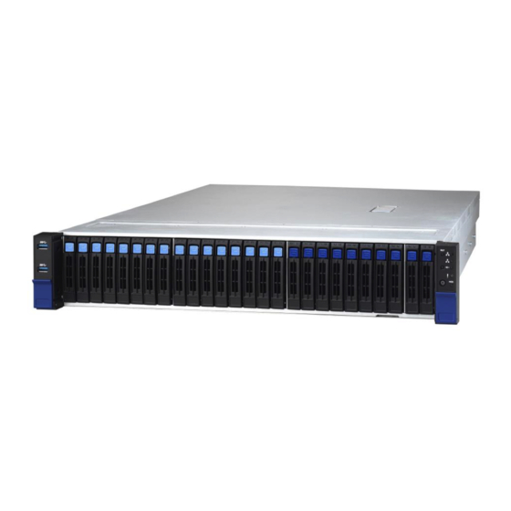
Page 26: About The Product
3.5” /2.5” SSD/HDD/NVMe bays RESET Button NVMe SKU #00 ~ #15 from M/B NVMe port #16 ~ #23 from SAS card (option) #24~ #25 from M/B SATA port LE SKU #00 ~ #19 from M/B SATA port #20~#25 from SAS card (option) http://www.tyan.com... - Page 27 DRIVE STATE Active LED (Green) Status LED (Red) Drive Present, No Active Solid on Drive Present with Active Blinking Don’t care Drive Failure Solid on Don’t care RAID Rebuild Blinking @4 Hz Don’t care Drive Locate Identifier Blinking @1 Hz http://www.tyan.com...
-
Page 28: System Rear View
Dedicate to IPMI Port (LAN3) VGA Port RJ45 LAN Port (LAN2/LAN1) Add-On Card field Dedicate to OCP Card Add-On Card field ID Button ID LED (Blue) ID LED State Color Description Blue System identified ID LED System not identified http://www.tyan.com... - Page 29 The chart below illustrates the different LED states. 10/100/1000 Mbps LAN Link/Activity LED Scheme Left LED Right LED Link Green 10 Mbps Active Blinking Green Link Green Green 100 Mbps Active Blinking Green Green Link Green Amber 1000 Mbps Active Blinking Green Amber No Link http://www.tyan.com...
-
Page 30: System Top View
1.5.3 System Top View http://www.tyan.com... - Page 31 HDD Module M1295TS65-BP12-8/M1296TS65-BP12E-8/M1298T65-BP12E-2 HDD Backplane Board (3) System fans M7100F48B-PDB Power Distribution Board M7063F86-PBP Power Backplane Board Power Module Riser Card Bracket (M8036-L24-3F, M8036-R24-3F pre-installed) Memory Slots CPU Sockets PCIE3.0 SLOT x24 OCP A Slot (OCP1_A) OCP B Slot (OCP1_B) http://www.tyan.com...
-
Page 32: Chapter 2: Setting Up
Caution! To avoid damaging the motherboard and associated components, use torque force within the range kgf/cm (6.09 lb/in) on each mounting screw for motherboard installation. Do not apply power to the board if it has been damaged. http://www.tyan.com... -
Page 33: Precautions
Working on a system that is connected to a power supply can be extremely dangerous. Follow the guidelines below to avoid damage to TS65A-B8036 or injury to yourself. Ground yourself properly before removing the top cover of the system. -
Page 34: Installing Motherboard Components
This section describes how to install components on to the mainboard, including CPUs, memory modules and add on cards. 2.1.1 Removing the Chassis Cover Follow these instructions to remove TS65A-B8036 chassis cover. 1. Release the latch on the left side. 2. Slide to lift the rear top cover up. http://www.tyan.com... -
Page 35: Removing The Air Duct
2.1.2 Removing the Air Duct 1. Remove two PCIE bracket and the air duct from the chassis. http://www.tyan.com... -
Page 36: Board Image
2.1.3 Board Image S8036GM2NE http://www.tyan.com... - Page 37 S8036GM2NE-LE This picture is representative of the latest board revision available at the time of publishing. The board you receive may not look exactly like the above picture. http://www.tyan.com...
-
Page 38: Block Diagram
2.1.4 Block Diagram S8036 Block Diagram http://www.tyan.com... -
Page 39: Motherboard Mechanical Drawing
2.1.5 Motherboard Mechanical Drawing http://www.tyan.com... -
Page 40: Board Parts, Jumpers And Connectors
The board you receive may not look exactly like the above diagram. The DIMM slot numbers shown above can be used as a reference when reviewing the DIMM population guidelines shown later in the manual. For the latest board revision, please visit our web site at http://www.tyan.com. http://www.tyan.com... - Page 41 29. CPU_FAN (CPU_FAN) 30. PCIE/SATA 74P SLIMSAS Connector 7. BCM5720 RJ45 LAN Connector (LAN3) (SLIMSAS2) 31. PCIE/SATA 74P SLIMSAS Connector 8. TYAN Module Header (DBG_HD1) (SLIMSAS1) 9. Rear ID LED Button (ID LED_BTN1) 32. Front Fan_3 (SYS_FAN_3) 10. HDT Header (HDT1) 33.
- Page 42 Onboard BMC IPMI ALERT LED (IPMI__LED2) v Rear ID LED (ID_LED2) x HDD_ACT_LED (HDD_LED3) NOTE: 1. SD card socket is an OEM-reserved feature which is not enabled on current product offering. 2. HDR_1-5: NVME Hotplug I2C connector for NVME HDD backplane. http://www.tyan.com...
-
Page 43: Installing The Cpu And Heatsink
Note: The force frame will automatically eject after the captive screws are being released. By placing your both index fingers on the sides on the metal handle, pull to release the rail frame. Then lift the rail frame to its fully open position. Remove the external cap from the rail frame. http://www.tyan.com... - Page 44 During installation, observe the following: 1. Make sure to push the carrier frame with package towards the end of the rail frame until it clicks into place. 2. Do not drop the carrier frame or touch the package pad to avoid component damage. http://www.tyan.com...
- Page 45 7. Close the force frame. Then use a T20 Torx screwdriver to tighten the screws to secure the force frame in a sequential order (1 ->2->3). 8. To secure the heatsink, use a T30 Security Torx to tighten the screws. Tighten the four screws in a diagonal sequence to secure the heat sink. http://www.tyan.com...
-
Page 46: Installing The Pci-E Card
2.1.8 Installing the PCI-E Card Follow these instructions to install the PCI-E card. 1. Unscrew the riser card bracket. 2. Remove the riser card bracket from the chassis. http://www.tyan.com... - Page 47 3. Unscrew to remove the dummy brackets. 4. Insert the PCI-E card into the riser card bracket and screw it firmly. Follow the same procedures to insert the card to the other side of the riser card bracket if necessary. http://www.tyan.com...
- Page 48 5. The same procedure to install the PCIE card to the second riser card. 6. Reposition and screw the riser card bracket into the chassis. http://www.tyan.com...
-
Page 49: Installing The Memory
2. Align the memory module with the slot. When inserted properly, the memory slot locking levers lock automatically onto the indentations at the ends of the module. Follow the recommended memory population table to install the other memory modules. http://www.tyan.com... - Page 50 Memory Population table http://www.tyan.com...
-
Page 51: Installing Hard Drives
2.1.10 Installing Hard Drives The TS65A-B8036 supports twenty-six 2.5” hot-swap HDD/NVMe SSDs and two 2.5” hot-swap SSDs. Installing 2.5” Hot-Swap Hard Drives Follow these instructions to install a 2.5” HDD. Warning!!! Always install the hard disk drive to the chassis after the chassis has been secured on the rack. - Page 52 Open the lock to place the 2.5” hard disk drive into the HDD tray. Lock the tray lever to secure HDD. Reinsert the HDD tray into the chassis. Push to secure the locking lever until it clicks into place. http://www.tyan.com...
- Page 53 Always install the hard disk drive to the chassis after the chassis has been secured on the rack. Press the locking lever latch and pull the locking lever open. Open the lock to place a 2.5” hard disk drive into the HDD tray. Lock the tray lever to secure HDD. http://www.tyan.com...
- Page 54 Reinsert the HDD tray into the chassis. Push to secure the locking lever until it clicks into place. http://www.tyan.com...
-
Page 55: Rack Mounting
19" rack. NOTE: Before mounting the TYAN TS65A-B8036 in a rack, ensure that all internal components have been installed and that the unit has been fully tested. However, to make the installation easier, we suggest that you remove all HDD trays before you insert the chassis into the rack. - Page 56 Align the inner sliding rail on the side of the server, and pull towards the arrow to secure the hooks Repeat steps 2 to 4 to secure the sliding rail to the other side of the server. http://www.tyan.com...
- Page 57 Secure the outer rails to the rack on each side. Rack Mounting the Server Draw out the middle rail to the latch position. When the inner rails come to a stop, pull the tab to release the latch and push the whole system in. http://www.tyan.com...
- Page 58 Secure the mounting ears of the unit to the rack using two M5 x 20L screws (A). http://www.tyan.com...
- Page 59 NOTE http://www.tyan.com...
-
Page 60: Chapter 3: Replacing Pre-Installed Components
Front Panel Board, M1718T65-USB Board, M1295T65-BP12-8/ M1296T65-BP12E-8 HDD Backplane, M1298T65-BP12-2 Power Distribution board, HDD Backplane, M7100F48B-PDB M7063F86-PBP Power Backplane Board. M8036-L24-3F M8036-R24-3F Riser cards, System fan and Power supply unit etc. Disassembly Flowchart The following flowchart outlines the disassembly procedure. http://www.tyan.com... -
Page 61: Removing The Cover
Removing the Cover Before replacing any parts you must remove the chassis cover first. Follow Chapter 2.1.1 to remove the cover of the TS65A-B8036. Replacing Motherboard Components Follow these instructions to replace motherboard components, including the motherboard. 3.4.1 Replacing the Riser Card... - Page 62 Unscrew the M8036-L24-3F riser card to replace with a new one. Unscrew the M8036-R24-3F riser card to replace with a new one. Follow the steps described earlier in reverse to reinstall the riser card bracket. http://www.tyan.com...
-
Page 63: Pci-E Riser Cards Specification
3.4.2 PCI-E Riser Cards Specification M8036-L24-3F Riser Card 3.4.3 Connector Pin Definition (M8036-L24-3F) Location Definition PCIe X16 SLOT 4P Power Connector PCIe X8 SLOT PCIe X8 SLOT http://www.tyan.com... -
Page 64: Connector Pin Definition (M8036-R24-3F)
M8036-R24-3F Riser Card 3.4.4 Connector Pin Definition (M8036-R24-3F) Location Definition PCIe X8 SLOT 4Pin Power Connector PCIe X16 SLOT PCIe X8 SLOT PCIe X1 SLOT Signal Signal J2 (PWR1) +12V http://www.tyan.com... -
Page 65: Replacing The Front Panel Board
Replacing the Front Panel Board Follow these instructions to replace the M1718T65-FPB Front Panel Board. 1 Unscrew to release the Front Panel Board cover. 2 Remove the Front Panel Board cover. http://www.tyan.com... - Page 66 3 Unscrew the Front Panel Board to replace a new one. 4 Disconnect the Front Panel Board to replace a new one. 5 Follow the steps described earlier in reverse to reinstall the Front Panel Board. http://www.tyan.com...
-
Page 67: Front Panel Board Specifications
Form Factor Thickness: 1.6mm Layer: 4 layers power button with LED reset button ID button Specifications LED: LAN1 LED (green), LAN2 LED (green), ID LED (blue), HDD LED (green/Red), FAULT LED (Red/green/Blue), Power LED http://www.tyan.com... -
Page 68: Replacing The Usb Board
Replacing the USB Board Follow these instructions to replace the M1717T65-USB Board. 1 Unscrew to release the USB front cover. 2 Remove the USB front cover. http://www.tyan.com... - Page 69 3 Unscrew the USB Board. 4 Disconnect the USB Board to replace a new one. 5 Follow the steps described earlier in reverse to reinstall the USB Board. http://www.tyan.com...
-
Page 70: Usb Board Specifications
3.6.1 USB Board Specifications M1717T65-USB USB Board PCB Dimensions: 48.00*19.00*1.6mm Form Factor Thickness: 1.6mm Layer: 4 layers USB 3.1 Connector Specifications 5*2PIN input Connector http://www.tyan.com... -
Page 71: Replacing The System Fan
Replacing the System Fan Follow these instructions to replace the fan. Take out the fan from the chassis. Replace a new fan to the chassis. Reinstall a new fan to the chassis. http://www.tyan.com... -
Page 72: Replacing The Hdd Backplane Board
Disconnect all cables connected to the M1295T65-BP12-8/ M1296T65-BP12E-8 HDD backplane Board. Unscrew the HDD BP Board. Release the HDD Backplane from the hook. Follow the procedures described earlier to reinstall the HDD backplane board bracket into the chassis. http://www.tyan.com... -
Page 73: Hdd Backplane Board Features
M1295T65-BP12-8 Front View Rear View PCB Dimensions: 131mm*76mm*3mm Form Factor Thickness: 3mm Layer: 6 layers 10-Pin FAN Header x 1 Specifications Mini SAS HD Connector x 2 (Input) Overview 5-Pin SGPIO Header x 1 SATA/SAS HDD x 8 (Output) http://www.tyan.com... -
Page 74: Connector Definition
SATA Connector HDD2 SATA Connector HDD3 SATA Connector HDD4 SATA Connector HDD5 SATA Connector HDD6 SATA Connector HDD7 SATA Connector SATA0_3 Mini SAS HD Connector SATA4_7 Mini SAS HD Connector Power Connector SGPIO0 SGPIO Header for HDD0~7 SGPIO1 Reserved http://www.tyan.com... - Page 75 PCB Dimensions: 131mm*76mm*3mm Form Factor Thickness: 3mm Layer: 8 layers 10 Pin FAN Header x 1 SlimSAS Connector x4 Input Specifications 5Pin SGPIO Header x 2 Overview NVMe HDD x 8 (Output) Smbus Header x1 (HDR_1) FAN Connector x 3 http://www.tyan.com...
-
Page 76: Replacing The Power Distribution Board
Power Distribution Board in your system. Disconnect all cables connected to the power distribution board. Unscrew to take off the power distribution board and replace with a new one. Insert the PDB into the chassis following the above procedures in reverse. http://www.tyan.com... -
Page 77: Power Distribution Board Features
Power Distribution Board Features M7100F48B-PDB Power Distribution Board Board Size 82mm x 127.3mm, 6-layer PCB (3) 8-pin power connector (3) 4-pin power connector (2) 20-pin power connector Integrated I/O (1) 24-pin power connector (1) PSMI connector (1) 50-pin golden finger http://www.tyan.com... -
Page 78: Pin Definitions
3.9.2 Pin Definitions J1: PSMI Connector Definition Definition SMBUS_Clock SMBUS_Data SMBUS_Alert PW1/PW4/PW9: 4-pin Power Connector Definition Definition PW6/PW7/PW8: 8-pin Power Connector Definition Definition PW2/PW3: 20-Pin Power Connector Definition Definition http://www.tyan.com... - Page 79 PW5: 24-pin Power Connector Definition Definition 3.3V 3.3V 3.3V PS_ON PW_GD 5VSB 3.3V http://www.tyan.com...
-
Page 80: Replacing The Power Backplane Board
Replacing the Power Backplane Board Follow these instructions to replace the M7063F86-PBP Power Backplane Board. Unscrew the Power BP Board bracket from the chassis. Remove the bracket beside and release the power distribution tray. Slide to take out the power backplane board tray. http://www.tyan.com... - Page 81 Unscrew to replace with a new power backplane board. Follow the steps described earlier in reverse order to reinstall the power backplane board tray into the chassis. http://www.tyan.com...
-
Page 82: Replacing The Rear Hdd Backplane Board
3.11 Replacing the Rear HDD Backplane Board Follow the instructions to replace the M1298T65-BP12-2 HDD backplane Board Disconnect all cables and unscrew the power distribution board. http://www.tyan.com... -
Page 83: Hdd Backplane Features
4P Power CON (PW1) Header for PCA9544 SMBUS address Select (3PHD-1) The rear 2 SATA SSDs/HDDs (SATA0 & SATA1) are not available when AMD EPYC™ 7002 Series Processors deployed in all configurations. Please contact Tyan Technical Support for more details. http://www.tyan.com... -
Page 84: Hdd Led Definition
3.11.2 HDD LED Definition Color State Description NVME/SATA/SAS HDD fail HDD fail LED No failure found NVME/SATA/SAS HDD ready Green HDD Power/Access Blinking NVME/SATA/SAS HDD access activity Power disconnected http://www.tyan.com... -
Page 85: Replacing The Power Supply
Follow these instructions to replace the power supply module in your system. Press the latch to pull the power supply out. After replacing a new power supply, press and hold the latch to push the power supply back into the chassis. http://www.tyan.com... -
Page 86: Disconnecting All Motherboard Cables
3.13 Disconnecting All Motherboard Cables Disconnect all cables connected to the motherboard. http://www.tyan.com... -
Page 87: Removing The Motherboard
After removing all of the aforementioned cables, follow the instructions below to remove the motherboard from the chassis. Remove the air duct, processor and heatsink if installed. Remove nine screws securing the motherboard to the chassis. Carefully lift the motherboard from the chassis. http://www.tyan.com... - Page 88 NOTE http://www.tyan.com...
-
Page 89: Appendix I: Installing Io Plate For Ocp Card
Appendix I: Installing IO Plate for OCP Card Follow these instructions to install the IO Plate for OCP Card. Here shows how to install the IO Plate for the dual-port LAN card M7062-I599-2T. Unscrew the riser card bracket. Remove the riser card bracket from the chassis. http://www.tyan.com... - Page 90 4. Take out the IO plate for LAN card. Use a screwdriver to break the LAN port’s semi shearing. Break one semi-shearing if a single-port LAN card is installed. Break both for a dual-port LAN card. http://www.tyan.com...
- Page 91 5. Insert the IO Plate to the OCP card LAN port. 6. Screw the IO Plate to the chassis http://www.tyan.com...
- Page 92 7. Insert the LAN card into the OCP slot 8. Secure the LAN card to the chassis http://www.tyan.com...
-
Page 93: Appendix Ii: Cable Connection Tables
Connect to S8036GM2NE-LE/MB M1295T65A-BP12-8 SlimSAS 8I to Mini-SAS SLIMSAS1 SlimSAS 8I to Mini-SAS Front Backplane (BP) Board to S8036MB HDD BP 2 Cable Connect to S8036GM2NE-LE/MB M1295T65A-BP12-8 SlimSAS 8I to Mini-SAS SLIMSAS2 SlimSAS 8I to Mini-SAS http://www.tyan.com... - Page 94 FAN_HD1 FAN Ctrl Cable HDD BP Connect to S8036GM2NE-LE/MB M1295T65A-BP12-8 FAN_HD1 Front Panel Control Cable Front Panel S8036GM2NE/MB Connect to M1701T70-FPB S8036GM2NE-LE/MB FPIO_2 Front Panel USB Cable Front Panel S8036GM2NE/MB Connect to M1702T70-USB S8036GM2NE-LE/MB USB3_FPIO1 http://www.tyan.com...
- Page 95 PSMI HD1 Power Supply Cables M7100F48B-PDB Connect to HDD BP M1297T65-BP12E-12 PW1, PW2 Power Supply Cables Front HDD BP M7100F48B-PDB Connect to M1298T65-BP12E-2 Power Supply Cables Rear HDD BP M7100F48B-PDB Connect to M1298T65-BP12E-2 http://www.tyan.com...
-
Page 96: Appendix Iii: Fan And Temp Sensors
(rpm) Temp Sensor: SYS_Air_Outlet(RT3) ,and MB_Air_Inlet(RT2) etc. They detect the system temperature around. NOTE: The system temperature is measured in a scale defined by AMD, not in Fahrenheit or Celsius. http://www.tyan.com... - Page 97 BIOS Temp Sensor Name Explanation: http://www.tyan.com...
- Page 98 The highest temperature of CPU0 D3 UMC1 channel F slot P0_D2_UMC1_CH_G The highest temperature of CPU0 D2 UMC1 channel G slot P0_D2_UMC0_CH_H The highest temperature of CPU0 D2 UMC0 channel H slot BIOS FAN Sensor Name Explanation CPU0_FAN Fan speed of CPU0_FAN http://www.tyan.com...
- Page 99 Fan speed of SYS_FAN_5 SYS_FAN_6 Fan speed of SYS_FAN_6 SYS_FAN_7 Fan speed of SYS_FAN_7 SYS_FAN_8 Fan speed of SYS_FAN_8 SYS_FAN_9 Fan speed of SYS_FAN_9 SYS_FAN_10 Fan speed of SYS_FAN_10 SYS_FAN_11 Fan speed of SYS_FAN_11 SYS_FAN_12 Fan speed of SYS_FAN_12 http://www.tyan.com...
-
Page 100: Appendix Iv: Fru Parts Table
Appendix IV: FRU Parts Table TS65A-B8036 FRU Parts Item Model Number Part Number Picture Description Power FRU-PS-0320 471100000417 1200 W,CHICONY Supply FRU-TH-0270 336210000065 22000RPM,40*40*28MM Heatsink FRU-TH-0310 343T60900003 Heatsink Air duct FRU-TA-0180 344T60900011 Air duct FRU-RC-1000 5411T6090008 M8036-L24-3F Riser Card PCBA... -
Page 101: Appendix V: Technical Support
MITAC serves multiple market segments with the industry’s most competitive services to support them. TYAN's tech support is some of the most impressive we've seen, with great response time and exceptional organization in general.” — Anandtech.com Please feel free to contact us directly for this service at tech-support@tyan.com... - Page 102 Return Merchandise Authorization (RMA) number. The RMA number should be prominently displayed on the outside of the shipping carton and the package should be mailed prepaid. TYAN will pay to have the board shipped back to you. ® TS65A-B8036 Service Engineer’s Manual V1.0b...
Need help?
Do you have a question about the TS65A-B8036 and is the answer not in the manual?
Questions and answers