Table of Contents
Advertisement
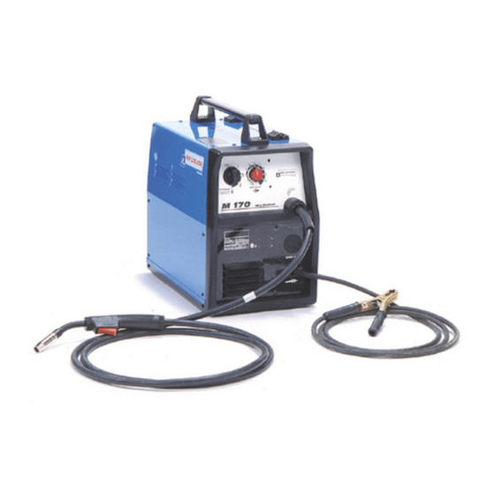
M 130 - M 170
The technical specifications and the wiring diagrams contained in this owner's manual are valid only
for the model that has the part number indicated below.
Air Liquide Welding is a trademark of L'Air Liquide S.A.
OWNER'S MANUAL
KEEP THIS MANUAL
M 130
ALW-M120500381
:
M 170
ALW-M120500382
:
08/01
Advertisement
Table of Contents
Troubleshooting

Related Manuals for Air Liquide M 130


Summary of Contents for Air Liquide M 130
- Page 1 The technical specifications and the wiring diagrams contained in this owner’s manual are valid only for the model that has the part number indicated below. M 130 ALW-M120500381 M 170 ALW-M120500382 Air Liquide Welding is a trademark of L’Air Liquide S.A. 08/01...
-
Page 2: Table Of Contents
..........20 10 M 130 – M 170 COMMON SPARE PARTS LIST . -
Page 3: Safety Precautions - Read Before Using
The publisher does not assume and hereby disclaims any liability to any party for any loss or damage caused by any error or omission in the Air Liquide M 130 – M 170 Owner’s Manual, whether such error results from neg- ligence, accident or any other causes. -
Page 4: Fire And Explosion Prevention
5. In the event that a welding operation occurs in a confined place, the operator should be accompanied by another person. Compressed gas cylinders are potentially dangerous. Consult the supplier 6. Always keep gas cylinders in a well-ventilated for correct handling procedures. Always protect area. -
Page 5: Radiation Can Cause Injury
1.9 WELDING AND THE EFFECTS OF LOW 1.7 H.F. RADIATION CAN CAUSE INJURY FREQUENCY AND MAGNETIC FIELDS As welding current flows through welding cables, it High frequency (HF) emissions can can cause electromagnetic fields. To reduce mag- interfere with radio navigation, safety devices, netic fields, use the following procedures: computers and communication equipment. - Page 6 EQUIPMENT INSTALLATION AND MAINTENANCE MUST BE PERFORMED IN COMPLIANCE WITH LOCAL SAFETY STANDARDS. Electric shock could be fatal Fumes and gases may repre- Use a protective mask with suit- sent a safety hazard. able glass filter (at least NR10) 1. Never touch exposed electrical Fumes and gases generated to safeguard eyes.
-
Page 7: Specifications And Description
2.3 COMES COMPLETE WITH: 1. 2.4 m (8 ft) input power cord with 5p-15 plug (M 130) or 6p-50 plug (M 170) 2. 3 m (10 ft) MIG gun 3. Extra contact tips 4. 3 m (10 ft) ground cable with clamp 5. -
Page 8: Duty Cycle And Overheating
Duty cycle is the percentage of 10 minutes that the unit can weld at its rated output without overheating. If the unit overheats, the weld output will stop. To correct this situation, wait fifteen minutes for the unit to cool. Reduce amperage or duty cycle before starting to weld again. M 130 Duty Cycle DUTY CHART M 130 30 40... -
Page 9: Volt-Ampere Curves
2.5 VOLT-AMPERE CURVES Volt-ampere curves show the maximum voltage and amperage output capabilities of the welding power source. Curves of other settings fall under curves shown. M 130 Volt-Ampere Curve Amps M 170 Volt-Ampere Curve Amps... -
Page 10: Installation
3. INSTALLATION CONNECTING THE EQUIPMENT TO 3.3 CHANGING POLARITY THE MAIN SUPPLY T U R N O F F W E L D E R B E F O R E M A K I N G CONNECTIONS. The equipment works within an input range of ±10%. - Page 11 INSTALLING WELDING GUN TURN OFF WELDER BEFORE MAKING CONNECTIONS. Supplied with machine...
-
Page 12: Installing Wire Spool And Adjusting Hub Tension
4. Remove gun nozzle and contact tip. vent slippage. 5. Press the gun trigger until wire comes out of 9. Cut off wire and begin welding. the welding gun. Typical Weld Parameter Settings : M 130 Typical Weld Parameter Settings : M 170... -
Page 13: Installing Sg 185 Spool Gun
3.7 INSTALLING SG 185 SPOOL GUN 1. Lift and position the side panel into an upright position. 2. Remove gun inlet cover located on the front panel of the welding machine. 3. Insert the SG 185 Spool Gun through the gun inlet. 4. -
Page 14: Operation
4 OPERATION FRONT PANEL CONTROLS DATA PLATE WIRE SPEED CONTROL Use this control to adjust wire feed speed. When M 130 wire speed is increased, welding amperage increases. When wire feed speed decreases, welding amperage decreases. M 170 VOLTAGE SWITCH Use this control to turn the wire feed unit on and to adjust welding voltage. -
Page 15: Replacing Gun Liner
REPLACING THE GUN LINER 1. Turn OFF welder. 2. Follow the instructions in the figure below: TROUBLESHOOTING TYPE OF BREAKDOWN POSSIBLE CAUSES CHECKS AND SOLUTIONS No functions operate Faulty power cord (one or more Check and remedy phases disconnected) Blown fuse Replace Irregular wire feed Insufficient spring pressure... -
Page 16: M 130 Electrical Diagram
6. M 130 ELECTRICAL DIAGRAM... -
Page 17: M 170 Electrical Diagram
7. M 170 ELECTRICAL DIAGRAM... -
Page 18: M 130 Spare Parts List
8. M 130 SPARE PARTS LIST... - Page 19 CODE...
-
Page 20: M 170 Spare Parts List
9. M 170 SPARE PARTS LIST... - Page 21 CODE...
-
Page 22: 130 - M 170 Common Spare Parts List
10. M 130 – M 170 COMMON SPARE PARTS LIST CODE CODE... -
Page 23: Mg 140 Spare Parts List
11. MG 140 SPARE PARTS LIST...