Table of Contents
Advertisement
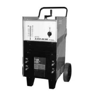
A 225 AC/DC - A 250 AC/DC
The technical specifications and the wiring diagrams contained in this owner's manual are valid only
OWNER'S MANUAL
KEEP THIS MANUAL
for the model that has the part number indicated below.
A 225 AC/DC
ALW-M110500425
:
A 250 AC/DC
ALW-M110500426
:
Air Liquide Welding is a trademark of L'Air Liquide S.A.
08/01
Advertisement
Table of Contents

Related Manuals for Air Liquide A 225 AC/DC: ALW-M110500425


Summary of Contents for Air Liquide A 225 AC/DC: ALW-M110500425
- Page 1 The technical specifications and the wiring diagrams contained in this owner’s manual are valid only for the model that has the part number indicated below. A 225 AC/DC ALW-M110500425 A 250 AC/DC ALW-M110500426 Air Liquide Welding is a trademark of L’Air Liquide S.A. 08/01...
-
Page 2: Table Of Contents
TABLE OF CONTENTS SAFETY PRECAUTIONS - READ BEFORE USING INSTALLATION OF EQUIPMENT ..........3 PERSONAL PROTECTION . -
Page 3: Safety Precautions - Read Before Using
The publisher does not assume and hereby disclaims any liability to any party for any loss or damage caused by any error or omission in the Air Liquide A 225 AC/DC – A 250 AC/DC Owner’s Manual, whether such error results from negligence, acci- dent or any other causes. -
Page 4: Fire And Explosion Prevention
5. In the event that a welding operation occurs in a confined place, the operator should be Compressed gas cylinders accompanied by another person. are potentially dangerous. Consult the supplier for correct handling procedures. Always protect 6. Always keep gas cylinders in a well-ventilated compressed gas cylinders from the sun’s rays, area. -
Page 5: Transporting The Power Source
1.7 H.F. RADIATION CAN CAUSE INJURY 1.9 WELDING AND THE EFFECTS OF LOW FREQUENCY AND MAGNETIC FIELDS As welding current flows through welding cables, it High frequency (HF) emissions can can cause electromagnetic fields. To reduce mag- interfere with radio navigation, safety devices, netic fields, use the following procedures: computers and communication equipment. -
Page 6: Principal Safety Standards
EQUIPMENT INSTALLATION AND MAINTENANCE MUST BE PERFORMED IN COMPLIANCE WITH LOCAL SAFETY STANDARDS. Electric shock could be fatal Fumes and gases may repre- Use a protective mask with suit- sent a safety hazard. able glass filter (at least NR10) 1. Never touch exposed electrical Fumes and gases generated to safeguard eyes. -
Page 7: Specifications And Description
2. SPECIFICATIONS AND DESCRIPTION 2.1 DESCRIPTION The 225 AC/DC sets a new standard for econom- The 250 AC/DC sets a new standard for AC/DC ical AC/DC arc welding machines. This ruggedly- arc welding machines. This ruggedly-built welder built welder is a proven performer with serious is a proven performer with serious amperage to amperage to burn 2.5 mm ( in) to 4.0 mm... -
Page 8: Duty Cycle And Overheating
2.4 DUTY CYCLE AND OVERHEATING: Duty cycle is the percentage of 10 minutes that the To correct this situation, wait fifteen minutes for the unit can weld at its rated output without overheat- unit to cool. Reduce amperage or duty cycle ing. -
Page 9: Volt-Ampere Curves
2.5 VOLT-AMPERE CURVES Volt-ampere curves show the maximum voltage and amperage output capabilities of the welding power source. Curves of other settings fall under curves shown. A 225 AC/DC A225 AC/DC MAX DC MAX AC MIN AC MIN DC Corrente (A) Amperage (A) A 250 AC/DC A250 AC/DC... -
Page 10: Operation
3. OPERATION 3.1 FRONT PANEL CONTROLS AMPERAGE ADJUSTMENT CONTROL 5/6. AC WELD OUTPUT RECEPTACLE POWER-ON LIGHT POSITIVE WELD OUTPUT RECEPTACLE POWER SWITCH NEGATIVE WELD OUTPUT RECEPTACLE AMPERAGE INDICATOR DATA PLATE... -
Page 11: Installation
4. INSTALLATION 4. Avoid areas where dust or other objects could be sucked into the system. Before connecting, preparing or using equipment, read Section 1: Safety Precautions. 5. Equipment must not obstruct corridors or work activities of other personnel. 7. Position the power source securely to avoid 4.1 CONNECTING THE EQUIPMENT TO falling or overturning. -
Page 12: Welding Parameters
4.4 WELDING PARAMETERS... -
Page 13: Internal Connection For Operating 230, 460 Or 575 Volts
4.5 INTERNAL CONNECTION FOR INSTALLING 230, 460 OR 575 VOLTS TURN OFF WELDER BEFORE MAKING CONNECTIONS. A 225 AC/DC A 250 AC/DC 575 V 230 V 460 V 230 V 460 V 4.6 HOW TO INSTALL THE WHEELS... -
Page 14: Maintenance And Troubleshooting
5. MAINTENANCE AND TROUBLESHOOTING Disconnect power before mainte- nance. Service more often during severe condi- tions. 5.1 ROUTINE MAINTENANCE Every three (3) months, perform the opera- tions below: 1. Replace unreadable labels 2. Clean and tighten weld terminal connections 3. Repair or replace worn hoses and cables 4. -
Page 15: A 225 Ac/Dc Electrical Diagram
6. A 225 AC/DC ELECTRICAL DIAGRAM A 225 AC/DC... -
Page 16: A 250 Ac/Dc Electrical Diagram
7. A 250 AC/DC ELECTRICAL DIAGRAM A 250 AC/DC... -
Page 17: A 225 Ac/Dc Spare Parts List
8. A 225 AC/DC SPARE PARTS LIST... -
Page 19: A 250 Ac/Dc Spare Parts List
9. A 250 AC/DC SPARE PARTS LIST...
Need help?
Do you have a question about the A 225 AC/DC: ALW-M110500425 and is the answer not in the manual?
Questions and answers