
Subscribe to Our Youtube Channel
Related Manuals for Microchip Technology Humidity Sensor PICtail


Summary of Contents for Microchip Technology Humidity Sensor PICtail
- Page 1 Humidity Sensor PICtail™ Demo Board User’s Guide © 2005 Microchip Technology Inc. DS51594A...
- Page 2 Mode, Smart Serial, SmartTel, Total Endurance, UNI/O, WiperLock and Zena are trademarks of Microchip Technology Incorporated in the U.S.A. and other countries. SQTP is a service mark of Microchip Technology Incorporated in the U.S.A. All other trademarks mentioned herein are property of their respective companies.
-
Page 3: Table Of Contents
1.5 Assembly Code Modules ................8 Chapter 2. Setup and Installation 2.1 Introduction ..................... 9 2.2 Required Tools ....................9 2.3 Setting up the Humidity Sensor PICtail™ Demo Board ......... 9 2.4 Connecting to Alternate Tools ..............11 Chapter 3. Operation 3.1 Introduction ....................13 3.2 Configuring the Humidity Sensor PICtail™... - Page 4 A.5 Additional Comments ................... 20 Appendix B. Bill Of Materials (BOM) B.1 Humidity Sensor PICtail™ Demo Board BOM ..........25 B.2 BOM for Humidity Sensor and Other Capacitors in Box ......26 B.3 BOM for “Reduced Current” Modifications ........... 26 Worldwide Sales and Service ..................28...
-
Page 5: Preface
• Customer Support • Document Revision History DOCUMENT LAYOUT This document describes how to use the Humidity Sensor PICtail™ Demo Board as a development tool to emulate and debug firmware on a target board. The manual layout is as follows: •... -
Page 6: Conventions Used In This Guide
Humidity Sensor PICtail™ Demo Board User’s Guide CONVENTIONS USED IN THIS GUIDE This manual uses the following documentation conventions: DOCUMENTATION CONVENTIONS Description Represents Examples Arial font: ® Italic characters Referenced books MPLAB IDE User’s Guide Emphasized text ...is the only compiler... -
Page 7: Recommended Reading
Preface RECOMMENDED READING This user's guide describes how to use Humidity Sensor PICtail™ Demo Board. Other useful documents are listed below and are recommended as supplemental reference resources. PICkit™ 2 Microcontroller Programmer User’s Guide (DS51553) Contains instructions on how to use the PICkit 2 Microcontroller Programmer hardware and software. -
Page 8: The Microchip Web Site
Humidity Sensor PICtail™ Demo Board User’s Guide THE MICROCHIP WEB SITE Microchip provides online support via our web site at www.microchip.com. This web site is used as a means to make files and information easily available to customers. Accessible by using your favorite Internet browser, the web site contains the following information: •... -
Page 9: Chapter 1. Product Overview
• Associated Tools • Initial Set-up KIT CONTENTS • Humidity Sensor PICtail™ Demo Board – This is an assembled and tested Printed Circuit Board (PCB). • CD-ROM – Provided separately in the shipping box; it contains the files and literature mentioned in this user’s guide. - Page 10 A 6-pin header for ICSP™ (In-Circuit Serial Programming™) is available as an alternate interface for programming the on-board PIC16F690. This allows the user to modify the ® program that comes with the Humidity Sensor PICtail™ Demo Board (with the MPLAB ICD 2 or PICkit™ 2 microcontroller programmer). Humidity Sensor PICtail™...
-
Page 11: Associated Tools
ASSOCIATED TOOLS Figure 1-2 shows the block diagram of the hardware and software tools that the Humidity Sensor PICtail™ Demo Board is designed to work with. More information on these tools can be found in the “Recommended Reading” section. Hardware Software Capacitance.exe... -
Page 12: Assembly Code Modules
Humidity Sensor PC Program The capacitance.exe PC Program communicates with the PIC16F690 MCU on the Humidity Sensor PICtail™ Demo Board through the USB port on the PICkit™ 1 Flash Starter Kit. It also imports data through the same connections and displays them. -
Page 13: Chapter 2. Setup And Installation
DEMO BOARD USER’S GUIDE Chapter 2. Setup and Installation INTRODUCTION This chapter shows how to set up the Humidity Sensor PICtail™ Demo Board. Items discussed in this chapter include: • Required Tools • Connecting the Humidity Sensor PICtail™ Demo Board •... - Page 14 Humidity Sensor PICtail™ Demo Board User’s Guide 2.3.1 PICkit™ 1 Flash Starter Kit 1. Remove any PICmicro microcontroller that may be in the Evaluation Socket. 2. Connect the USB cable to the PC and to the PICkit™ 1 Flash Starter Kit board.
-
Page 15: Connecting To Alternate Tools
PICkit™ 2 Microcontroller Programmer An exploded view of how the PICkit™ 2 microcontroller programmer connects to the Humidity Sensor PICtail™ Demo Board is shown in Figure 2-2. This setup is an alternative way to reprogram the PIC16F690 on the Humidity Sensor PICtail™ Demo Board. - Page 16 Humidity Sensor PICtail™ Demo Board User’s Guide NOTES: © 2005 Microchip Technology Inc. DS51594A-page 12...
-
Page 17: Chapter 3. Operation
The capacitance.exe PC Program Graphical User Interface (GUI) is displayed in Figure 3-1. It is a simple program that helps the user to control the functionality of the Humidity Sensor PICtail™ Demo Board and to view the results sent back from that board. - Page 18 Humidity Sensor PICtail™ Demo Board User’s Guide 1.f. 1.e. 1.c. 2.e. 2.d. 2.e. 2.d. 4.b. 4.a. 2.c. 1.d. 2.f. 1.g. 3.b. 3.c. 1.e. 2.d. 3.a. FIGURE 3-1: “Humidity Sensor PC Program” GUI. The following steps will help familiarize the user with this GUI. The step numbers are displayed in Figure 3-1.
-
Page 19: Humidity Sensor Calibration
In both cases, there are two areas of concern. First, the RH can change rapidly across time and position, making an accurate calibration difficult to do. Second, it takes time for humidity sensors to settle to an accurate value. Some can take many minutes to settle properly. © 2005 Microchip Technology Inc. DS51594A-page 15... - Page 20 Humidity Sensor PICtail™ Demo Board User’s Guide NOTES: © 2005 Microchip Technology Inc. DS51594A-page 16...
-
Page 21: Chapter 4. Modified Circuit
THE “REDUCED CURRENT” CIRCUIT 4.2.1 Modifications Figure 4-1 shows the Humidity Sensor PICtail™ Demo Board top silk-screen. Figure 4-1 also shows the locations of the resistors that need to be modified to implement the “Reduced Current” circuit discussed in application note AN1016: 1. - Page 22 Interpreting the Output from the Humidity Sensor PC Program The capacitance.exe PC program displays measured capacitance values assuming the Humidity Sensor PICtail™ Demo Board has not been modified. To correct the dis- played values, move the displayed decimal point to the left two places (e.g., 321.0 pF is actually 3.210 pF).
-
Page 23: Appendix A. Schematic And Layouts
HUMIDITY SENSOR PICTAIL™ DEMO BOARD USER’S GUIDE Appendix A. Schematic and Layouts INTRODUCTION This appendix contains the schematics and layouts for the Humidity Sensor PICtail™ Demo Board. HIGHLIGHTS The Humidity Sensor PICtail™ Demo Board is constructed using a two-layer Printed Circuit Board (PCB). -
Page 24: The "Reduced Current" Modification
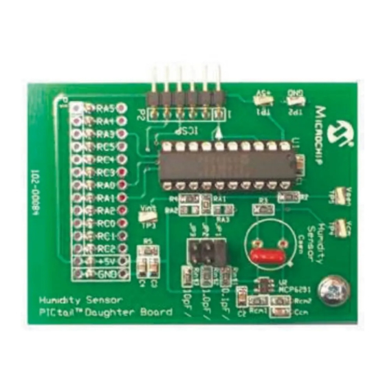
00084R1.zip. THE “REDUCED CURRENT” MODIFICATION Figure A-1 shows the Humidity Sensor PICtail™ Demo Board as it comes from Microchip. This board can be modified by the user to implement the “Reduced Current” circuit discussed in application note AN1016 and Chapter 4. “Modified Circuit”. - Page 25 10kΩ Csen OPEN 1.0pF/ 0Ω 66.5 kΩ HS1101LF 10pF/ 66.5 kΩ OPEN Humidity +5VA 0.1 μF +5VA MCP6291 20 kΩ 20 kΩ 0.1μF NOTE: All Resistors are 1% FIGURE A-1: Board – Schematic. © 2005 Microchip Technology Inc. DS51594A-page 21...
- Page 26 Humidity Sensor PICtail™ Demo Board User’s Guide 100Ω +5VA 1 μF 1 μF ICSP ICSPDAT ICSPCLK NOTE: All Resistors are 1% FIGURE A-2: Board – Schematic. (Continued) © 2005 Microchip Technology Inc. DS51594A-page 22...
- Page 27 Schematic and Layouts FIGURE A-3: Board – Top Silk-Screen. FIGURE A-4: Board – Top Metal Layer. © 2005 Microchip Technology Inc. DS51594A-page 23...
- Page 28 Humidity Sensor PICtail™ Demo Board User’s Guide FIGURE A-5: Board – Bottom Metal Layer. © 2005 Microchip Technology Inc. DS51594A-page 24...
-
Page 29: Appendix B. Bill Of Materials (Bom)
HUMIDITY SENSOR PICTAIL™ DEMO BOARD USER’S GUIDE Appendix B. Bill Of Materials (BOM) HUMIDITY SENSOR PICTAIL™ DEMO BOARD BOM Table B-1 shows the BOM for the Humidity Sensor PICtail™ Demo Board as it comes from Microchip. TABLE B-1: BILL OF MATERIALS... -
Page 30: Bom For Humidity Sensor And Other Capacitors In Box
Humidity Sensor PICtail™ Demo Board User’s Guide BOM FOR HUMIDITY SENSOR AND OTHER CAPACITORS IN BOX Table B-2 lists capacitors included separately in the Humidity Sensor PICtail™ Demo Board’s shipping box. These capacitors or the HS1101LF sensor will fit in the Csen pin recepticles. - Page 31 Bill Of Materials (BOM) NOTES: © 2005 Microchip Technology Inc. DS51594A-page 27...
-
Page 32: Worldwide Sales And Service
Fax: 949-462-9608 Tel: 886-2-2500-6610 Fax: 86-29-8833-7256 San Jose Fax: 886-2-2508-0102 Mountain View, CA Thailand - Bangkok Tel: 650-215-1444 Tel: 66-2-694-1351 Fax: 650-961-0286 Fax: 66-2-694-1350 Toronto Mississauga, Ontario, Canada Tel: 905-673-0699 Fax: 905-673-6509 10/31/05 © 2005 Microchip Technology Inc. DS51594A-page 28...
Need help?
Do you have a question about the Humidity Sensor PICtail and is the answer not in the manual?
Questions and answers