
Subscribe to Our Youtube Channel
Related Manuals for Microchip Technology BM77 PICtail


Summary of Contents for Microchip Technology BM77 PICtail
- Page 1 ___________________________________________________________________________ BM77 PICtail / PICtail Plus Board User’s Guide 2015 Microchip Technology Inc. DRAFT Page 1 ...
-
Page 2: Table Of Contents
2.2. Mode Switch Settings ............................6 2.3. USB-UART Interface ............................6 2.4. PICtail Interface ............................... 7 3. Quick Start Guide to Using the BM77 PICtail Board ............9 3.1. BM77 PICtail Board in USB-UART Serial Interface Mode ..........9 3.1. -
Page 3: Overview
This document describes the hardware and software for the BM77 PICtail/ PICtail Plus board. The BM77 PICtail board allows the designer to evaluate and demonstrate the capabilities of the BM77 Dual Mode Bluetooth RF Module. The evaluation board includes an integrated configuration and programming interface for plug-and-play capability. -
Page 4: Features
BM77 PICtail / PICtail Plus Board 1.2. Features Fully certified on board Bluetooth 3.0+EDR and Bluetooth 4.0 stack. Class 2 transmitter, +2dBM typical. Transparent serial data connection over Bluetooth Classic Serial Port Profile (SPP) and Bluetooth Low Energy transparent serial data service. -
Page 5: Interface Description
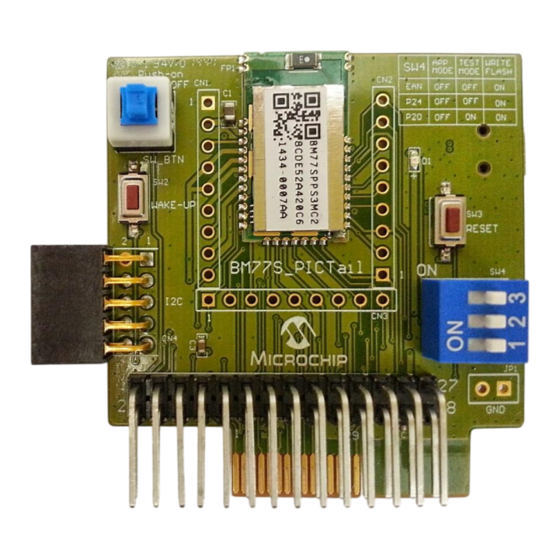
BM77 PICtail / PICtail Plus Board 2. Interface Description The illustration below shows a BM77 PICtail board in its default configuration as shipped. (below) Description 1. FP1- Bluetooth Module- BM77 2. SW1- Button to SW_BTN pin. The button must be pressed down to turn on BM77. -
Page 6: Mode Definitions
MCP2200 USB-UART serial converter for easy interfacing with a host PC. Connecting the mini-B USB receptacle (P1) on the BM77 PICtail board to the USB port on a PC will enumerate the BM77 PICtail board as a Composite Device Class (CDC) USB device for serial communication. After the MCP2200 enumerates, a dedicated COM port is assigned on the host PC for serial communication with the BM77 on the BM77 PICtail board. -
Page 7: Pictail Interface
Using the PICtail Plus (J2) or PICtail (J1) interface, the board can be plugged into any standard Microchip development board that supports the PICtail Plus, or PICtail, connection interface. The BM77 PICtail board can be plugged in to the PICtail or PICtail Plus interface headers available on Microchip development boards like the Explorer 16 Development Board (DM240001) or the PIC18 Explorer Board (DM183032). - Page 8 The BM77 PICtail board can be inserted into the PICtail Plus interface header or PICtail interface header available on Microchip development tools as shown in the illustrations. Note: Ensure that the BM77 module on the board is facing the PIC PIM while inserting the BM77 PICtail board into either of the PICtail headers.
-
Page 9: Quick Start Guide To Using The Bm77 Pictail Board
As illustrated below, the host PC runs a BT Chat Tool application, which transfers serial data over a COM port (USB virtual COM port) to BM77 PICtail, which is then transmitted over a Bluetooth connection to the remote Bluetooth 2015 Microchip Technology Inc. - Page 10 Step 3. Verify SW1 button is in the ON position (pushed down). Step 4. Using the mini-B USB cable, connect the BM77 PICtail board mini-B USB receptacle (P1) to a host PC USB port to power up BM77 PICtail board.
- Page 11 BM77 PICtail / PICtail Plus Board A virtual COM port should be created when the BM77 PICtail board is connected to a PC. If a virtual COM is not observed in the Device Manager port list, it may be necessary to install Microchip MCP2200 driver. (Search Internet by typing keywords ”Microchip MCP2200 Driver”...
- Page 12 The Black text are sent from PC tool (BM77 PICtail board) to smart phone The Red texts are sent from smart phone to the PC tool (BM77 PICtail board) Click the check box of Burst Send to repeatedly send the text from this tool.
- Page 13 BM77 PICtail / PICtail Plus Board 2015 Microchip Technology Inc. DRAFT Page 13 ...
- Page 14 Press Scan button to initiate the Bluetooth Device scan Find the BM77 PICtail board device named “Dual-SPP” and select it to start the pairing process. Once paired, the Dual-SPP (BM77 PICtail board) device will be listed in paired device list.
- Page 15 BM77 PICtail / PICtail Plus Board Step 9. Launch the BtChat APP on Android Device a. BT Chat APP main window is displayed. b. Use the Android menu button to open BT Chat menu options. Select the Setting button to open APP setting view.
- Page 16 From BT Chat APP main window, press the Android menu button to open BT Chat menu options. Select the Connect a device button to open paired device list. b. Select the “Dual-SPP” device to open an SPP connection to BM77 PICtail board. c. After connection is established the status message is displayed in main window.
- Page 17 PC. c. Observe received text in red color font on Bluetooth Chat PC tool window. d. Enter text to send to BM77 PICtail board in Bluetooth Chat tool on PC. e. Click “Send” to transmit text to BTChat Android APP.
-
Page 18: Bluetooth Low Energy Data Connection To Ios Device
3.1.2. Bluetooth Low Energy Data Connection to iOS Device This demonstration show how serial data is transmitted from BM77 PICtail board (via PC Chat) to an iOS device using Bluetooth Low Energy (BLE) connection. This demonstration uses ISSC BLETR APP to establish connection with the BM77 PICtail board. - Page 19 Launch the ISSC BLETR APP and it will scan for the Bluetooth Low Energy Peripheral devices and list them. If the device does not appear, press the Refresh or Scan button to restart the BTLE peripheral scan. Find the Dual-SPP BTLE peripheral device. Select it to start a connection to the BM77 PICtail board named Dual-SPP.
- Page 20 BM77 PICtail / PICtail Plus Board After a successful connection to BM77 PICtail board, BLETR will display the Dual-SPP device as connected as shown below. Select the connected Dual-SPP device to display the top level view. This view presents three options when connected to a BM77 PICtail board.
- Page 21 BM77 PICtail / PICtail Plus Board Device Info- This view displays the settings for Bluetooth Low Energy Device Information Service. 2015 Microchip Technology Inc. DRAFT Page 21 ...
- Page 22 BM77 PICtail / PICtail Plus Board Selecting Transparent button opens the transparent serial data view as shown below. The default mode is Raw (ASCII) mode where any data characters received are displayed in the large text box in red font.
- Page 23 BM77 PICtail / PICtail Plus Board To send data from BLETR iOS device to the BM77, select the input text box. The soft keyboard will be displayed as shown below. Enter text in the input text box. Click Send button to transmit text to BM77 over BLE connection.
- Page 24 BM77 PICtail / PICtail Plus Board Timer Feature In addition to Raw mode (ASCII) the Transparent data view also has Timer and Echo features. The Timer feature allows the BLETR to send a repeated test pattern to BT Chat PC tool for throughput and data transfer test.
- Page 25 BM77 PICtail / PICtail Plus Board 2015 Microchip Technology Inc. DRAFT Page 25 ...
- Page 26 BM77 PICtail / PICtail Plus Board Tx File Feature Another test feature similar to the Timer feature is the “TX File” transfer. The “TX File” functions transfers files, which is embedded in the BLETR APP, to the BM77. The steps to use this feature are as follows.
- Page 27 BM77 PICtail / PICtail Plus Board Echo Feature The Echo feature is an optional function for the Transparent mode data view. When Echo is enabled, any data received by BLETR is echoed back to sender. The example below show text sent from BT Chat PC tool being echoed to BLETR when the Echo mode is enabled.
- Page 28 The Device Information view displays the characteristics associated with Device Information service. The Device Information service is available to all Bluetooth 4.0 low energy host that access the BM77 PICtail board. It exposes the identification information about the BM77 BLE peripheral device.
- Page 29 BM77 PICtail / PICtail Plus Board Proprietary (Configuration) Feature The Proprietary view demonstrates the capability to change Bluetooth Low Energy connection parameters remotely via BLETR application. These parameters only affect Bluetooth Low Energy connections. 1. Max Interval: time (ms) between communication interval between BM77 and Bluetooth LE Central device.
-
Page 30: Bm77 Pictail Board In Pictail Interface Mode
3.2. Using BM77 PICtail Board in PICtail Interface Mode This section provides an overview of tools that can be used to configure the BM77 module on the BM77 PICtail board using a PIC MCU through the PICtail interface. The BM77 Configuration User Interface (UI) Tool is used to change Bluetooth parameters and generate an EEPROM configuration dump file. - Page 31 BM77 PICtail / PICtail Plus Board Step 3. Browse to import the default EEPROM configuration dump file (bm77_eeprom_configuration_dump_default.txt) provided with the application and click Open button. Step 4. Click Edit button after the default EEPROM configuration dump file has been imported in to the BM77 UI tool.
- Page 32 BM77 PICtail / PICtail Plus Board Step 5. The BM77 UI tool will open the Bluetooth configuration window with various tabs to configure various available parameters. Configure the parameters as desired for your specific application by checking Help button for each parameter.
- Page 33 BM77 PICtail / PICtail Plus Board Step 7. Click Save button to save the updated EEPROM configuration dump file. The new EEPROM configuration dump file will be different from the default EEPROM configuration dump file that was imported in Step 3. due to the updates made to the Bluetooth parameters using the BM77 UI tool by the user.
-
Page 34: Bm77 Eeprom Table Utility
BM77 PICtail / PICtail Plus Board 3.2.2. BM77 EEPROM Table Utility The BM77 EEPROM Table Utility is used to create a file with an EEPROM table structure from the EEPROM configuration dump file that is created by the BM77 Configuration User Interface (UI) Tool as seen in the previous Section 3.2.1. - Page 35 BM77 PICtail / PICtail Plus Board Step 3. A file browse dialog box opens so that the user can browse and open the EEPROM configuration dump file created using the BM77 Configuration UI tool. File browser dialog box for the user to browse and open the EEPROM dump file: Browse and open the EEPROM configuration dump file by clicking Open button.
- Page 36 BM77 PICtail / PICtail Plus Board Message dialog box warning the user of the error while opening the EEPROM dump file: Step 4. User is prompted to browse, assign a name and save the EEPROM table file to be used by the BM77 2015 Microchip Technology Inc.
- Page 37 BM77 PICtail / PICtail Plus Board Configuration Library. Click OK button on the message dialog box. Message on the command window prompting the user to save the EEPROM table in the next step: Message dialog box prompting the user to save the EEPROM table file in the next step: Step 5.
- Page 38 BM77 PICtail / PICtail Plus Board file to be used by the BM77 Configuration Library. File browser dialog box for the user to browse and save the EEPROM table file: Type in a file name and click Save button to save the EEPROM table file. The file path is indicated on the command window and the application goes to next step.
- Page 39 BM77 PICtail / PICtail Plus Board Message dialog box warning the user of the error while saving the EEPROM table file: Step 6. The application creates the EEPROM table structure file. The progress is shown on the command window. 2015 Microchip Technology Inc.
- Page 40 BM77 PICtail / PICtail Plus Board The EEPROM table is created in the file chosen by the user in Step 5. After an EEPROM table file (bm77_eeprom_table.txt) is successfully created a success message is displayed on the command window and a message dialog box.
- Page 41 BM77 PICtail / PICtail Plus Board command window and an error dialog box. Click OK button on the error dialog box and restart the application with a good EEPROM configuration dump file if desired. Message on the command window showing the error due to corrupted EEPROM dump file: Message dialog box warning the user of the error due to corrupt EEPROM configuration dump file.
-
Page 42: Bm77 Configuration Library
BM77 configuration library refer to the „BM77ConfigLibraryHelp.chm‟ file. The BM77 configure demo showcases a proof-of-concept example of interfacing the BM77 PICtail Plus with a PIC microcontroller (MCU). In this demonstration the BM77 module on the BM77 PICtail can be configured through the PIC MCU. - Page 43 UART can be used to transfer data to and from the BM77. The BM77 PICtail uses Universal Asynchronous Receiver/Transmitter (UART) interface and the General Purpose Input Output (GPIO) Ports to configure, control and transfer data to the PIC MCU. For more information on the UART configuration, refer the BM77 Module Datasheet.
- Page 44 Section 3.1.1. and Section 3.1.2. specifically related to using the BTChat APP on Android and ISSC BLETR APP can be used to pair, connect and transfer data to the BM77 PICtail board with the exception being that the BM77 PICtail board will be interfaced to a PIC MCU over the PICtail interface and transfers data through the PICtail interface and not the USB-UART MCP2200 interface.
- Page 45 Step 2. Observe the BM77 configuration by putting break points in the workspace or by optionally using the debug UART mentioned above. Step 3. Download and install the “BtChat_V1.0.3.apk” on the Android device from the BM77 PICtail Plus webpage. Step 4. Open the “BtChat” app installed by the “BtChat_V1.0.3.apk” on the Android device.
-
Page 46: Appendix A: Bm77Spp03 Module Pin Assignment
BM77 PICtail / PICtail Plus Board 4. Appendix A: BM77SPP03 Module PIN Assignment BT_RF1 BT_RF BAT_IN BAT_IN SW_BTN SW_BTN LED1 LDO33_O VDD_IO LDO18_O P34/SCLK WAKEUP WAKEUP_SI1 P33/MOSI PMULDO_O PMULDO_O P32/MISO P31/NCS UART_TXD HCI_TXD P12/SCL UART_RXD P12 / SCL HCI_RXD P13/SDA... - Page 47 BM77 PICtail / PICtail Plus Board Name Description STATUS_IND: Bluetooth link status indication P15/P04: HH Power default value and Shutdown State. P15/P04: HL Access State. P15/P04: LL Link State w/o UART_TXD. P15/P04: LH Link State with UART_TXD.
-
Page 48: Appendix B: Bm77 Pictail / Pictail Plus Board Schematics
BM77 PICtail / PICtail Plus Board 5. Appendix B: BM77 PICtail / PICtail Plus Board Schematics 2015 Microchip Technology Inc. DRAFT Page 48 ... - Page 49 BM77 PICtail / PICtail Plus Board 2015 Microchip Technology Inc. DRAFT Page 49 ...
- Page 50 BM77 PICtail / PICtail Plus Board 2015 Microchip Technology Inc. DRAFT Page 50 ...
-
Page 51: Appendix C: Q & A
Yes. The BM77 data sheet is available for download on www.microchip.com/bm77. 2. When I connect the BM77 PICtail board to the host PC the COM port does not appear? Try unplugging the USB cable and plugging it back to the PC. Check if the MCP2200 drivers are installed. If not download and install the MCP2200 drivers. - Page 52 BM77 PICtail / PICtail Plus Board Notes: 2015 Microchip Technology Inc. DRAFT Page 52 ...
Need help?
Do you have a question about the BM77 PICtail and is the answer not in the manual?
Questions and answers