Table of Contents
Advertisement
Quick Links
AVR64EA48 Curiosity Nano Hardware User Guide
Preface
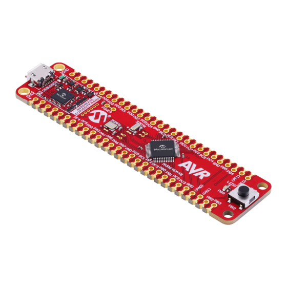
The AVR64EA48 Curiosity Nano evaluation kit (EV66E56A) is a hardware platform to evaluate the AVR
microcontrollers. This board has the AVR64EA48 microcontroller (MCU) mounted.
Supported by both MPLAB
AVR64EA48 to explore how to integrate the device into a custom design.
The Curiosity Nano series of evaluation boards include an on-board debugger. No external tools are necessary to
program and debug the AVR64EA48.
®
•
MPLAB
X IDE
and
Microchip Studio
Microchip microcontrollers.
•
Code examples on MPLAB Discover
•
AVR64EA48 website
•
AVR64EA48 Curiosity Nano website
©
2023 Microchip Technology Inc.
and its subsidiaries
®
X IDE and Microchip Studio, the board provides easy access to the features of the
- Software to discover, configure, develop, program, and debug
- Get started with code examples.
- Find documentation, data sheets, sample, and purchase microcontrollers.
- Kit information, latest user guide and design documentation.
AVR64EA48
User Guide
®
EA Family
DS50003494A-page 1
Advertisement
Table of Contents

Related Manuals for Microchip Technology AVR64EA48


Summary of Contents for Microchip Technology AVR64EA48
-
Page 1: Preface
AVR64EA48 AVR64EA48 Curiosity Nano Hardware User Guide Preface ® The AVR64EA48 Curiosity Nano evaluation kit (EV66E56A) is a hardware platform to evaluate the AVR EA Family microcontrollers. This board has the AVR64EA48 microcontroller (MCU) mounted. ® Supported by both MPLAB X IDE and Microchip Studio, the board provides easy access to the features of the AVR64EA48 to explore how to integrate the device into a custom design. -
Page 2: Table Of Contents
The Microchip Website..........................41 Product Change Notification Service....................41 Customer Support..........................41 Microchip Devices Code Protection Feature..................41 Legal Notice............................41 Trademarks............................42 Quality Management System........................ 43 Worldwide Sales and Service........................44 User Guide DS50003494A-page 2 © 2023 Microchip Technology Inc. and its subsidiaries... -
Page 3: Introduction
– 1.8–5.1V output voltage (limited by USB input voltage) – 500 mA maximum output current (limited by ambient temperature and output voltage) Board Overview The Microchip AVR64EA48 Curiosity Nano evaluation kit is a hardware platform to evaluate the AVR64EA48 microcontroller. Figure 1-1. AVR64EA48 Curiosity Nano Board Overview... -
Page 4: Getting Started
Connect a USB cable (Standard-A to Micro-B or Micro-AB) between the PC and the debug USB port on the board. Program your application onto the device. The AVR64EA48 device on the AVR64EA48 Curiosity Nano board is programmed and debugged by the on-board debugger. Therefore, no external programmer or debugger tool is required. Info: ... -
Page 5: Design Documentation And Relevant Links
Tip: The latest device family packs are available through Tools > Device Pack Manager in Microchip Studio or online at Microchip Studio Packs Repository. Design Documentation and Relevant Links The following list contains links to the most relevant documents and software for the AVR64EA48 Curiosity Nano board: ® ® ®... - Page 6 - MPLAB Discover is a tool to help you find Microchip example projects and collateral for Microchip devices. • AVR64EA48 Curiosity Nano website - Kit information, latest user guide and design documentation. • AVR64EA48 Curiosity Nano on Microchip Direct - Purchase this kit on Microchip Direct. User Guide DS50003494A-page 6 © 2023 Microchip Technology Inc.
-
Page 7: Curiosity Nano
A Data Gateway Interface (DGI) for code instrumentation with logic analyzer channels (debug GPIO) to visualize program flow The on-board debugger controls a Power and Status LED (marked PS) on the AVR64EA48 Curiosity Nano board. The table below shows how the different operation modes control the LED. - Page 8 On Mac machines, the CDC will enumerate and appear as /dev/tty.usbmodem#. Depending on the terminal program used, it will appear in the available list of modems as usbmodem#. User Guide DS50003494A-page 8 © 2023 Microchip Technology Inc. and its subsidiaries...
- Page 9 The target device may enable the internal pull-up resistor on the pin connected to the debugger’s CDC TX pin to avoid glitches resulting in unpredictable behavior like framing errors. User Guide DS50003494A-page 9 © 2023 Microchip Technology Inc. and its subsidiaries...
- Page 10 A break character is defined as a sequence of at least 11 zero bits transmitted from the host to the device. Not all UART receivers have support for detecting a break, but a correctly-formed break character usually triggers a framing error on the receiver. User Guide DS50003494A-page 10 © 2023 Microchip Technology Inc. and its subsidiaries...
- Page 11 STATUS.TXT – a text file containing the programming status of the board Info: The on-board debugger dynamically updates STATUS.TXT. The contents may be cached by the OS and, therefore, may not reflect the correct status. User Guide DS50003494A-page 11 © 2023 Microchip Technology Inc. and its subsidiaries...
- Page 12 (Debugger firmware v1.25.6 or newer.) CMD:3V3 Sets the target voltage to 3.3V. If external power is provided, this has no effect. (Debugger firmware v1.25.6 or newer.) User Guide DS50003494A-page 12 © 2023 Microchip Technology Inc. and its subsidiaries...
- Page 13 GPIO data. It is available as a plug-in for MPLAB X IDE or a stand-alone application that can be used in parallel with MPLAB X IDE or Microchip Studio. Although DGI encompasses several physical data interfaces, the AVR64EA48 Curiosity Nano implementation includes logic analyzer channels: •...
-
Page 14: Curiosity Nano Standard Pinout
The USB port powers the board. It contains two LDO regulators, one to generate 3.3V for the on-board debugger and an adjustable LDO regulator for the target AVR64EA48 microcontroller and its peripherals. The voltage from a USB connector can vary between 4.4V and 5.25V (according to the USB specification) and will limit the maximum voltage supplied to the target. - Page 15 1.7V to 5.1V. Additional output voltage limits are configured in the debugger firmware to ensure that the output voltage never exceeds the hardware limits of the AVR64EA48 microcontroller. The voltage limits configured in the on-board debugger on AVR64EA48 Curiosity Nano are 1.8–5.5V.
- Page 16 3.3.2 External Supply Instead of the on-board target regulator, an external voltage can power the AVR64EA48 Curiosity Nano. When shorting the Voltage Off (VOFF) pin to the ground (GND) pin, the on-board debugger firmware disables the target regulator, and it is safe to apply an external voltage to the VTG pin.
- Page 17 VBUS Output Pin AVR64EA48 Curiosity Nano has a VBUS output pin that can be used to power external components that need a 5V supply. The VBUS output pin has a PTC fuse to protect the USB against short circuits. A side effect of the PTC fuse is a voltage drop on the VBUS output with higher current loads.
-
Page 18: Low-Power Measurement
Low-Power Measurement Power to the AVR64EA48 is connected from the on-board power supply and VTG pin through a 100 mil pin-header marked with “POWER” in silkscreen (J101). To measure the power consumption of the AVR64EA48 and other peripherals connected to the board, cut the Target Power strap and connect an ammeter over it. -
Page 19: Programming External Microcontrollers
Connections. The on-board level shifters can be completely disconnected to prevent leakage, as described 7.4. Disconnecting the On-Board Debugger. Programming External Microcontrollers Use the on-board debugger on AVR64EA48 Curiosity Nano to program and debug microcontrollers on external hardware. 3.5.1 Supported Devices All external AVR microcontrollers with the UPDI interface can be programmed and debugged with the on-board debugger with Microchip Studio. - Page 20 3.5.3 Hardware Modifications The on-board debugger is connected to the AVR64EA48 by default. Remove these connections before any external microcontroller can be programmed or debugged. Cut the GPIO straps shown in the figure below with a sharp tool to disconnect the AVR64EA48 from the on-board debugger.
- Page 21 GPIO straps(bottom side) Info: Cutting the connections to the debugger will disable programming, debugging, and data streaming from the AVR64EA48 mounted on the board. Tip: Solder 0Ω resistors across the footprints or short circuit them with solder to reconnect the signals between the on-board debugger and the AVR64EA48.
-
Page 22: Connecting External Debuggers
Even though there is an on-board debugger, external debuggers can be connected directly to the AVR64EA48 Curiosity Nano to program/debug the AVR64EA48. When not actively used, the on-board debugger keeps all the pins connected to the AVR64EA48 and board edge in tri-state. Therefore, the on-board debugger will not interfere with any external debug tools. - Page 23 AVR64EA48 Curiosity Nano ™ ® Figure 3-11. Connecting the MPLAB PICkit 4 In-Circuit Debugger/Programmer to AVR64EA48 Curiosity Nano 1 = Unused MPLAB® PICkit™ 4 2 = VDD 3 = Ground 4 = PGD 5 = Unused 6 = Unused 7 = Unused...
- Page 24 AVR64EA48 Curiosity Nano Figure 3-12. Connecting the Atmel-ICE to AVR64EA48 Curiosity Nano AVR® Atmel-ICE Ground 1 = Unused 6 = Unused 2 = GND 7 = Unused 3 = UPDI 8 = Unused 4 = VTG 9 = Unused 5 = Unused...
-
Page 25: Hardware Description
AVR64EA48 Curiosity Nano Pinout All the AVR64EA48 I/O pins are accessible at the edge connectors on the board. The image below shows the board pinout. Refer to the I/O Multiplexing and Considerations section in the AVR64EA48 data sheet for all available functions on each pin. -
Page 26: Peripherals
Important: Once the pin-headers are in place, they are hard to remove by hand. Use a set of pliers and carefully remove the pin-headers to avoid damage to the pin-headers and PCB. Peripherals User Guide DS50003494A-page 26 © 2023 Microchip Technology Inc. and its subsidiaries... - Page 27 Hardware Description 4.2.1 One yellow user LED is available on the AVR64EA48 Curiosity Nano board. It can be controlled by either GPIO or PWM. Driving the connected I/O line to GND can also activate the LED. Table 4-1. LED Connection...
- Page 28 Hardware Description The 20.00 MHz crystal is connected to AVR64EA48 on PA0 and PA1, which are also routed to the edge connector through two solder points. PA0 and PA1 are disconnected from the edge connector by default to reduce the chance of an external signal causing contention with the crystal and to remove excessive capacitance on the lines.
- Page 29 PF1 on the bottom side of the board (J210, J211) Figure 4-5. Crystal Connection and Cut Straps 32.768 kHz Crystal J207 J211 J210 J208 J209 Top Side Bottom Side User Guide DS50003494A-page 29 © 2023 Microchip Technology Inc. and its subsidiaries...
-
Page 30: Hardware Revision History And Known Issues
Identifying Product ID and Revision There are two ways to find the revision and product identifier of the AVR64EA48 Curiosity Nano: Either by utilizing the MPLAB X IDE or Microchip Studio Kit Window or by looking at the sticker on the bottom of the PCB. -
Page 31: Document Revision History
AVR64EA48 Document Revision History Document Revision History Doc. Rev. Date Comments 02/2023 Initial document release User Guide DS50003494A-page 31 © 2023 Microchip Technology Inc. and its subsidiaries... -
Page 32: Appendix
AVR64EA48 Appendix Appendix User Guide DS50003494A-page 32 © 2023 Microchip Technology Inc. and its subsidiaries... -
Page 33: Schematic
Schematic rotatethispage90 Figure 7-1. AVR64EA48 Curiosity Nano MCU Schematic rotatethispage90 AVR64EA48 DEBUGGER CONNECTIONS NOTE on UART/CDC: CDC_RX AVR64EA48 CDC_RX CDC_TX RX/TX on the header denotes the CDC_TX Debugger Name C200 input/output direction of the signal DBG0 respective to it's source. - Page 34 Schematic rotatethispage90 Figure 7-2. AVR64EA48 Curiosity Nano Debugger Schematic rotatethispage90 Interface ICSP UPDI TARGET ADJUSTABLE REGULATOR TARGET TARGET Signal VCC_VBUS J100: VCC_REGULATOR VCC_LEVEL VCC_EDGE CDC TX UART RX UART RX - Cut-strap used for full separation of target power from the level shifters and on-board regulators.
-
Page 35: Assembly Drawing
AVR64EA48 Appendix Assembly Drawing Figure 7-3. AVR64EA48 Curiosity Nano Assembly Drawing Top Figure 7-4. AVR64EA48 Curiosity Nano Assembly Drawing Bottom User Guide DS50003494A-page 35 © 2023 Microchip Technology Inc. and its subsidiaries... -
Page 36: Curiosity Nano Base For Click Boards
AVR64EA48 Appendix ™ Curiosity Nano Base for Click boards Figure 7-5. AVR64EA48 Curiosity Nano Pinout Mapping User Guide DS50003494A-page 36 © 2023 Microchip Technology Inc. and its subsidiaries... -
Page 37: Disconnecting The On-Board Debugger
The on-board debugger and level shifters can be completely disconnected from the AVR64EA48. The block diagram below shows all connections between the debugger and the AVR64EA48. The rounded boxes represent connections to the board edge. The signal names shown are also printed in silkscreen on the bottom side of the board. -
Page 38: Getting Started With Iar
GCC. Programming and ™ debugging of AVR64EA48 Curiosity Nano is supported in IAR Embedded Workbench for AVR using the Atmel-ICE interface. To get the programming and debugging to work, some initial settings must be set up in the project. - Page 39 AVR64EA48 Appendix Figure 7-8. Select Target Device Figure 7-9. Select Debugger User Guide DS50003494A-page 39 © 2023 Microchip Technology Inc. and its subsidiaries...
- Page 40 AVR64EA48 Appendix Figure 7-10. Configure Interface User Guide DS50003494A-page 40 © 2023 Microchip Technology Inc. and its subsidiaries...
-
Page 41: Microchip Information
Microchip products with your application. Use of this information in any other manner violates these terms. Information regarding device applications is provided only for your convenience and may be superseded User Guide DS50003494A-page 41 © 2023 Microchip Technology Inc. and its subsidiaries... -
Page 42: Trademarks
The Adaptec logo, Frequency on Demand, Silicon Storage Technology, and Symmcom are registered trademarks of Microchip Technology Inc. in other countries. GestIC is a registered trademark of Microchip Technology Germany II GmbH & Co. KG, a subsidiary of Microchip Technology Inc., in other countries. -
Page 43: Quality Management System
AVR64EA48 Quality Management System For information regarding Microchip’s Quality Management Systems, please visit www.microchip.com/quality. User Guide DS50003494A-page 43 © 2023 Microchip Technology Inc. and its subsidiaries... -
Page 44: Worldwide Sales And Service
Tel: 631-435-6000 Sweden - Stockholm San Jose, CA Tel: 46-8-5090-4654 Tel: 408-735-9110 UK - Wokingham Tel: 408-436-4270 Tel: 44-118-921-5800 Canada - Toronto Fax: 44-118-921-5820 Tel: 905-695-1980 Fax: 905-695-2078 User Guide DS50003494A-page 44 © 2023 Microchip Technology Inc. and its subsidiaries...
Need help?
Do you have a question about the AVR64EA48 and is the answer not in the manual?
Questions and answers