Table of Contents
Advertisement
Quick Links
OPERATOR'S MANUAL
1000 AND 1500 WATT SWITCHING POWER SUPPLY
VOLTAGE/CURRENT-STABILIZED DC SOURCE
KEPCO INC.
An ISO 9001 Company.
IMPORTANT NOTES:
1)
This manual is valid for the following Model and associated serial numbers:
MODEL
2)
A Change Page may be included at the end of the manual. All applicable changes and
revision number changes are documented with reference to the equipment serial num-
bers. Before using this Instruction Manual, check your equipment serial number to identify
your model. If in doubt, contact your nearest Kepco Representative, or the Kepco Docu-
mentation Office in New York, (718) 461-7000, requesting the correct revision for your
particular model and serial number.
3)
The contents of this manual are protected by copyright. Reproduction of any part can be
made only with the specific written permission of Kepco, Inc.
Data subject to change without notice.
©2012, KEPCO, INC
P/N 243-0850b
KEPCO, INC.
131-38 SANFORD AVENUE
HSM SERIES
MODEL
HSM SERIES
POWER SUPPLY
SERIAL NO.
FLUSHING, NY. 11355 U.S.A.
email: hq@kepcopower.com
REV. NO.
KEPCO
THE POWER SUPPLIER™
TEL (718) 461-7000
World Wide Web: http://www.kepcopower.com
®
FAX (718) 767-1102
Advertisement
Table of Contents

Related Manuals for KEPCO HSM 3.3-230


Summary of Contents for KEPCO HSM 3.3-230
-
Page 1: Power Supply
Before using this Instruction Manual, check your equipment serial number to identify your model. If in doubt, contact your nearest Kepco Representative, or the Kepco Docu- mentation Office in New York, (718) 461-7000, requesting the correct revision for your particular model and serial number. -
Page 3: Table Of Contents
TABLE OF CONTENTS SECTION PAGE SECTION 1 - INTRODUCTION Scope of Manual ............................. 1-1 General Description..........................1-1 Specifications ............................1-1 Miscellaneous Features .......................... 1-5 1.4.1 Control/programming ......................... 1-5 1.4.2 Status Flags:............................1-5 1.4.3 Setpoint Monitors:..........................1-5 1.4.4 Remote Error Sensing: ........................1-5 1.4.5 Load Sharing: ............................ -
Page 4: List Of Figures
TABLE OF CONTENTS SECTION PAGE 3.13 Module Current Monitor .......................... 3-7 3.14 Status Flags............................3-8 3.14.1 Source Power Status Flags ......................3-8 3.14.2 OUTPUT Status Flags ........................3-9 3.14.3 OVERTEMP Status Flags......................... 3-10 3.14.4 FANFAIL Status Flags ........................3-10 LIST OF FIGURES FIGURE PAGE HSM Series Power Supply ........................... -
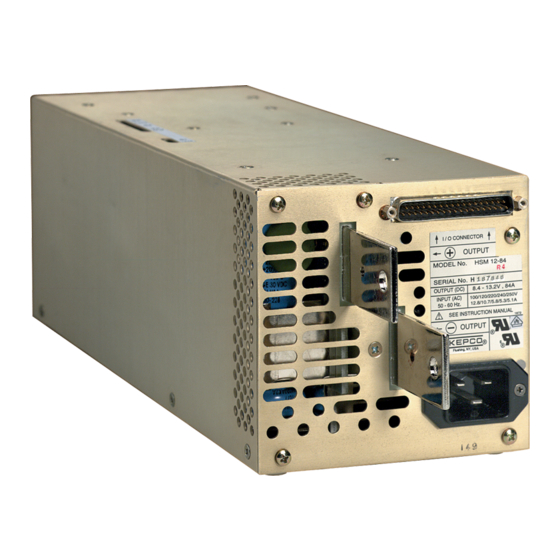
Page 6: Hsm Series Power Supply
FIGURE 1-1. HSM SERIES POWER SUPPLY (iii Blank)/iv HSMSERIES OPR 052912... -
Page 7: Section 1 - Introduction
Kepco RA 58 (or similar) rack adapters are available for EIA standard rack mounting. For applications requiring plug-in or hot-swap power supply modules refer to Kepco HSP Series power supplies. - Page 8 TABLE 1-2. GENERAL SPECIFICATIONS CHARACTERISTIC REQUIREMENT CHARACTERISTIC REQUIREMENT SOURCE INPUT OUTPUT/LOAD AC: Single-Phase, See Table 1-1. Nominal Voltage 1000W 1500W See Table 1-1. Nominal : 100-250V rms 200-250V rms Rated Current Range: 90-277Vrms 180-277V rms Source Voltage 2% of rated load (lower output conditions may Minimum Output result in increased output ripple and increased Current...
-
Page 9: Temperature Derating
TABLE 1-2. GENERAL SPECIFICATIONS (CONTINUED) CHARACTERISTIC REQUIREMENT CHARACTERISTIC REQUIREMENT SIGNAL AND CONTROL ENVIRONMENT 3.3V & 5V Models 0.25V per wire 0 to 50° C: rated load; 50° C to 71° C: derate by Remote Error Sensing Operating 0.8V per wire All other Models Temperature Range 2.5%/°... -
Page 10: Outline Drawing
FIGURE 1-3. OUTLINE DRAWING HSMSERIES OPR 052912... -
Page 11: Miscellaneous Features
MISCELLANEOUS FEATURES 1.4.1 CONTROL/PROGRAMMING a)VOLTAGE CHANNEL: Output voltage is controlled continu- ously throughout the specified adjustment range via a 10-turn potentiometer accessed through the top cover. External control can be exercised either by resistance or by control voltage (see PAR.s 3.3 and 3.4). CURRENT CHANNEL: Output current is controlled continuously throughout the specified adjustment range via a 10-turn potentiometer accessed through the top cover. -
Page 12: Options
OPTIONS HSM options are described below: 1.5.1 BATTERY CHARGER (B SUFFIX): The battery charger option incorporates an expanded window for the output voltage fault detector compatible with normal battery operating voltages. ACCESSORIES Accessories for HSM Power Supplies are listed in Table 1-3. TABLE 1-3. -
Page 13: Section 2 - Installation
SECTION 2 - INSTALLATION UNPACKING AND INSPECTION This instrument has been thoroughly inspected and tested prior to packing and is ready for operation. After careful unpacking, inspect for shipping damage before attempting to operate. Perform the preliminary operational check as outlined in PAR. 2.5. If any indication of damage is found, file an immediate claim with the responsible transport service. -
Page 14: Hsm Series Rear Panel Connections
FIGURE 2-2. HSM SERIES REAR PANEL CONNECTIONS TABLE 2-2. I/O CONNECTOR PIN ASSIGNMENTS PIN NO. NAME DESCRIPTION OF FUNCTION REF. PAR. NO CONNECTION NO CONNECTION FAN STATUS - NORMALLY CLOSED CONTACT FFS-1 3.14 SOURCE POWER STATUS - COMMON CONTACT ACS-C 3.14 SOURCE POWER STATUS - NORMALLY CLOSED CONTACT ACS-2... -
Page 15: Source Power Requirements
1. THE POWER SUPPLY WILL NOT OPERATE UNLESS THE REMOTE SENSE LINES ARE PROPERLY CONNECTED TO THE OUTPUT TERMINALS! Connect the remote sense ter- minals to the output bus bars using the mating I/O Connector (Kepco P/N 142-0422) or other means as shown in PAR. 2.7.5.1 and Figure 2-3. -
Page 16: Installation
3-wire safety line cord via a polarized mating plug. Kepco offers as accessories (see Table 1-3) both a user-wired mating connector and a prewired linecord set, the latter configured for North American applications. Terminal assignment follows internationally accepted conventions (see Figure 2-3). -
Page 17: D-C Output Grounding
Grounding a single point in the output circuit can be of great importance. It is hoped that the preceding paragraphs will be of some assistance in most cases. For help in special applications or difficult problems, consult directly with Kepco's Application Engineering Department. 2.7.4... -
Page 18: Load Connection - General
The use of the proper fastener size and inclusion of a lockwasher are critical to maintaining intimate contact between the load conductor and output bus bar; Kepco recom- mends the use of fasteners made of conductive material (brass, phosphor bronze, etc.) to enhance conductivity;... -
Page 19: Load Connection - Method I (Local Error Sensing)
2.7.5.1 LOAD CONNECTION - METHOD I (LOCAL ERROR SENSING) The most basic power supply/load interface is a 2-wire connection between the power supply output terminals and the load. This connection method employs local error sensing which con- sists of connecting the error sense leads directly to the power supply's output terminals. Its main virtue is simplicity: since voltage regulation is maintained at the power supply output, the regulation loop is essentially unaffected by the impedances presented by the load interconnec- tion scheme. -
Page 20: Load Connection - Method Ii (Remote Error Sensing)
2.7.5.2 LOAD CONNECTION - METHOD II (REMOTE ERROR SENSING) If the load is located at a distance from the power supply terminals, or if reactive and/or modu- lated loads are present, remote error sensing should be used to minimize their effect on the volt- age stabilization. -
Page 21: Load Connection - Method Iii (Series Connection)
2.7.5.3 LOAD CONNECTION - METHOD III (SERIES CONNECTION) Units may be connected in series to obtain higher output voltages. Each power supply in the series should be protected by a clamping diode connected in its non-conducting direction in par- allel with the output; this diode protects the power supply outputs against secondary effects in the event of a load short. -
Page 22: Load Connection - Method Iv (Parallel/Redundant Operation)
2.7.5.4 LOAD CONNECTION - METHOD IV (PARALLEL/REDUNDANT OPERATION) Identical HSM power supply models may be connected in parallel in order to provided increased output current to a common load (see Figure 2-6). This permits the user to obtain significantly higher load ratings than for a single HSM power supply. The number of power supplies required is determined by dividing the required load current by the current rating of the applicable HSM model, and rounding up to the next whole number when necessary. -
Page 23: Load Sharing
2.7.6 LOAD SHARING When operating two or more power supplies in parallel, either for capacity or redundancy, it is desirable to distribute the load equally among all of the power supplies in order to improve perfor- mance, reduce stress and increase reliability. HSM power supplies incorporate active circuitry which forces multiple power supplies wired in parallel to share load current, both in voltage- and current-mode regulation. -
Page 24: Signal Connections
2.7.7 SIGNAL CONNECTIONS The I/O Signal Connector, located on the rear panel of the HSM power supply (see Figure 2-2), provides access for all programming inputs and status signal outputs. These signals provide the user access to portions of the regulation control circuitry of the HSM and, as such, must be protected from radiated and conducted noise as well as from physical contact with non-valid driving sources. -
Page 25: Section 3 - Operating Instructions
SECTION 3 - OPERATING INSTRUCTIONS OPERATING CONFIGURATION The following subsections review the various features and indicate how to select and operate each function. The default settings for each function indicate the as-shipped status for standard HSM series power supplies. Prior to applying source power, the operating configuration of the HSM power supply must be selected. -
Page 26: Output Voltage Range
(0-10V) connected between pins 18 and 19 (VPROG, -S) of the I/O connector (see Figure 3-2). This technique is useful when imple- menting digital control of the power supply output voltage via a D/A converter; Kepco's SN/SNR 488 programmers are ideally suited to these requirements. -
Page 27: Current Limit Programming Range
(0-10V) connected between pins 15 and 19 (IPROG, -S) of the I/O connector (see Figure 3-3). This technique is useful when implement- ing digital control of the power supply current limit via a D/A converter; Kepco's SN/SNR 488 programmers are ideally suited to these requirements. -
Page 28: Overvoltage Protection Adjustment
Measurement quantities are defined as follows: , VSET: This voltage represents 1/10 of the programmed output voltage. As an example, VSET (or V ) = 4.63V corresponds to a programmed output voltage of 46.3V ±1%. This relationship is constant, regardless of the programming range selected (see PAR. 3.4). -
Page 29: Current Limit Characteristic
The signal generated by the OVP detector is gated with a signal from the fault detector circuit to produce a selective overvoltage shutdown function which prevents shutdown of operational power supplies in a parallel-redundant power system configuration. The OVP latches of any working power supplies are disabled, allowing only the faulty modules to be latched off;... -
Page 30: Current Walk-In Circuit
3.10 CURRENT WALK-IN CIRCUIT HSM power supplies incorporate a specialized output regulator start-up circuit for applications involving use of the HSM as a battery charger. This circuit, enabled via switch S1-2, overrides the normal duty-cycle-based soft-start circuit, which could still result in very fast output current rise rates into a discharged battery, and substitutes a controlled-current rise circuit with a time constant in accordance with Bellcore TR-TSY-000947 requirements for telecommunications bat- tery rectifiers (see Figure 3-4). -
Page 31: Remote Inhibit/Remote Reset Controls
3.12 REMOTE INHIBIT/REMOTE RESET CONTROLS HSM power supplies incorporate two TTL-level inputs, RC1 and RC2, accessed via the I/O con- nector, which can be used to disable the output regulator via external stimulus. These two con- trols operate from an internal 5V supply (5VAUX) which is isolated from both input and output (see PAR. -
Page 32: Status Flags
and isolated from the ISHARE signal, so that it cannot affect the load share function if shorted. The voltage level of this signal is generated with respect to the negative sense return (pin 19). 3.14 STATUS FLAGS HSM power supplies provide electrical indication of the status of various critical functions includ- ing source power status, output status, fan status and overtemperature condition. -
Page 33: Output Status Flags
3.14.2 OUTPUT STATUS FLAGS The OUTPUT STATUS flags are controlled by the output fault detector circuit, which monitors both output voltage and module current to assess d-c output status. An output fault condition is generated if one of three fault conditions is detected: (1) Overvoltage fault, (2) Undervoltage Fault - output voltage is outside specified regulation limits, or (3) Undercurrent fault - the power supply module is supplying less than 70% of the current required by the circuit (as indicated by the load sharing signal) while the output voltage is within specification limits. -
Page 34: Overtemp Status Flags
Table 3-2 provides an operating matrix of the output status function; see Figure 3-6 for timing relationships. The output voltage fault limits are ±5% of programmed output voltage, while the undercurrent fault limit is <70% of required module current; signal reset requires output voltage recovery to within the specified ±1% regulation range and/or module current recovery to >85% of required module current, respectively.
Need help?
Do you have a question about the HSM 3.3-230 and is the answer not in the manual?
Questions and answers