Table of Contents
Advertisement
OPERATOR'S MANUAL
SINGLE PHASE, POWER FACTOR CORRECTED
KEPCO INC.
An ISO 9001 Company.
IMPORTANT NOTES:
1)
This manual is valid for the following Model and associated serial numbers:
MODEL
HSF A, AM 600 Watts
2)
A Change Page may be included at the end of the manual. All applicable changes and
revision number changes are documented with reference to the equipment serial num-
bers. Before using this Instruction Manual, check your equipment serial number to identify
your model. If in doubt, contact your nearest Kepco Representative, or the Kepco Docu-
mentation Office in New York, (718) 461-7000, requesting the correct revision for your par-
ticular model and serial number.
3)
The contents of this manual are protected by copyright. Reproduction of any part can be
made only with the specific written permission of Kepco, Inc.
Data subject to change without notice.
©2015, KEPCO, INC
P/N 243-1352-r3
KEPCO, INC. 131-38 SANFORD AVENUE FLUSHING, NY. 11355 U.S.A. TEL (718) 461-7000 FAX (718) 767-1102
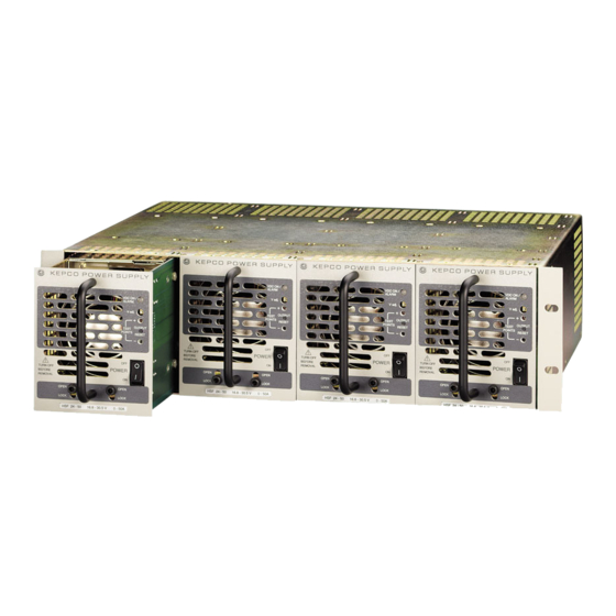
HSF A, AM 600 WATTS
POWER SUPPLY
SINGLE OUTPUT POWER SUPPLIES
UNIVERSAL AC INPUT
HSF A, AM 600 WATTS
POWER SUPPLY
HSF 12-53A, HSF 15-43A,
HSF 24-27A, HSF 28-23A, HSF 48-13A
HSF 12-53AM, HSF 15-43AM,
HSF 24-27AM, HSF 28-23AM, HSF 48-13AM
SERIAL NO.
email: hq@kepcopower.com World Wide Web: http://www.kepcopower.com
MODEL
REV. NO.
KEPCO
THE POWER SUPPLIER™
®
Advertisement
Table of Contents

Subscribe to Our Youtube Channel
Related Manuals for KEPCO HSF 12-53A


Summary of Contents for KEPCO HSF 12-53A
-
Page 1: Power Supply
Data subject to change without notice. KEPCO ® ©2015, KEPCO, INC THE POWER SUPPLIER™ P/N 243-1352-r3 KEPCO, INC. 131-38 SANFORD AVENUE FLUSHING, NY. 11355 U.S.A. TEL (718) 461-7000 FAX (718) 767-1102 email: hq@kepcopower.com World Wide Web: http://www.kepcopower.com... -
Page 2: Table Of Contents
TABLE OF CONTENTS SECTION PAGE 1. Introduction ................................ 1 Scope of Manual ............................. 1 Description ..............................1 2. Specifications..............................2 Features................................6 DIP Switch Configuration ..........................6 Front Panel Access............................8 Keying ................................8 Output Voltage Control ........................... 8 3.4.1 Front Panel Voltage Control......................... -
Page 3: Introduction
HSF AM Series, as well as with Kepco’s earlier 600 Watt HSF Series (non A). When integrating A and non A models refer to PAR’s. 3.5 and 3.7.2.2 regarding isolation of the return signal of the RC and PF features. Unless otherwise noted, all data supplied herein for A models applies to AM models as well. -
Page 4: Specifications
TABLE 1. HSF A REAR CONNECTOR PIN ASSIGNMENT Signal Function Name Output + 1, 2, 4 DC output (+) applied to load. Output – 3, 5, 6 DC Output (–) applied to load. SENSE– Sense– connection. IMON+ Current Monitor+ (sense resistor). SENSE+ Sense+ connection. -
Page 5: Power Rating Vs. Temperature
TABLE 2. HSF 600W (A, AM) OUTPUT RATINGS AND SPECIFICATIONS HSF A MODEL 12-53A, AM 15-43A, AM 24-27A, AM 28-23A, AM 48-13A, AM Output Volts d-c (nominal) Output Adjustment SW1 pos 7 OFF (default) 4.8 to 13.8 6 to 17.4 9.6 to 28.2 9.6 to 29.0 19.2 to 52.2... -
Page 6: Power Supply Ratings And Specifications
TABLE 3. POWER SUPPLY RATINGS AND SPECIFICATIONS CHARACTERISTIC SPECIFICATION CONDITION/NOTES Input Voltage Nominal: 100-120V a-c, 200-240V a-c 0 to 100% load, -10 to 50°C Range: 85-265V a-c, 120-330V d-c CAUTION: Input voltage exceeding specifications may damage the unit. Input Source Frequency Nominal: 50-60 Hz 0 to 100% load, -10 to 50°C Range: 47-63 Hz... - Page 7 (U.S. and Canadian), CE Mark (RoHS ver- 50-60Hz, ambient temperature 40°C max. sions) RoHS Compliance RoHS versions available; contact Kepco Sales for further information. EMC Emission - Conducted: Designed to meet FCC Class B, VCCI-Class B, EN55011-B, EN55022-B EMC Emission - Radiated:...
-
Page 8: Features
B) PCB 0.063" THK FR-4 C) FRONT PANEL 0.090 THK. ALUM. 6061-T6 SEE DETAIL "A" 2. FINISH: FRONT PANEL -KEPCO DUAL TONE GRAY 3. MODULE IS KEYED AS SHOWN IN DETAIL 4. DIMENSIONS ARE IN INCHES, [DIMENSIONS IN BRACKETS 3043321 ARE IN MILLIMETERS]. -
Page 9: Dip Switch Configuration
TABLE 4. DIP SWITCH 1 AND 2 FUNCTIONS DIP Switch 2 (left) DIP Switch 1 (right) Position Function Position Function OFF: Front panel Vadj controls output. OFF: Remote voltage or resistance controls output. See PAR. 3.4.1. See PAR. 3.4.2. ON: Remote voltage or resistance controls out- ON: Front panel Vadj controls output. -
Page 10: Front Panel Access
FRONT PANEL ACCESS. The front panel provides a power ON/OFF switch controlling input power and a “VDC ON” indica- tor which lights green when the unit is operating. If the unit is connected in a parallel configuration, the indicator lights red if the unit shuts off automatically, or the POWER switch is set to OFF. CAUTION: DO NOT repeatedly toggle the power ON/OFF switch as this may cause unit to fault. -
Page 11: Front Panel Controls, Indicators And Test Points (Hsf Am, Typical)
VDC ON/ALARM Indicator Voltage/Current Meter V. ADJ Output Voltage Adjustment Trimmer TEST POINT (+) Meter Mode switch OUTPUT RESET switch V (Voltage) indicator TEST POINT (-) POWER ON/OFF switch A (Amperes) indicator Retaining Latches 3043129 • VDC ON/ALARM indicator. Lights green when unit is oper- ating. -
Page 12: Remote Voltage Control
3.4.2 REMOTE VOLTAGE CONTROL Output voltage can be controlled remotely by means of an external voltage or resistance instead of by Vadj. Configure the DIP switches as follows: SW1: pos1 to ON, pos2 to ON; SW2: pos 1 to OFF, Pos2 to OFF NOTE: Configuring the unit for remote output voltage control disables the front panel Vadj con- trol. -
Page 13: Remote On-Off
(unlike earlier (non A) HSF 600W models). This return is connected to the power supply –OUTPUT. Please contact Kepco if appli- cation requires remote control to be isolated from DC output or from PF signal. -
Page 14: Protection Circuits
USE FRONT PANEL USE REMOTE ON-OFF RESET BUTTON (LOGICAL LEVEL OR (FACTORY DEFAULT) MECHANICAL SWITCH) +RC 3 3 +RC +RC 3 3 +RC -RC & -PF 4 4 -RC & -PF -RC & -PF 4 4 -RC & -PF 3043784 FIGURE 8. -
Page 15: Undervoltage
3.6.4 UNDERVOLTAGE If power supply output voltage either falls within 40 to 80% of the rated output voltage value, or is programmed below the minimum values listed in Table 5, an alarm occurs if the internal relay alarm (factory default, see PAR. 3.7.2.1) is enabled. To restart (reset) the unit, press and release the OUTPUT RESET switch on the front panel or, if the remote on/off feature is in use (see PAR. -
Page 16: Dip Switch Settings For Optically Coupled Logical Alarm
NOTE: Unlike earlier (non A) HSF 600W models, –PF and –RC are connected together and cannot be isolated from each other. This return is connected to the power sup- ply –OUTPUT when position 4 of SW1 is set to ON (factory default). If it is neces- sary to isolate the –PF and –RC from the power supply output, set position 4 of SW1 to OFF. -
Page 17: Local/Remote Sensing
FIGURE 12. ±PF POWER FAILURE OPTOCOUPLER TIMING DIAGRAM LOCAL/REMOTE SENSING HSF (A, AM) 600W Power Supplies allow remote error sensing which can compensate up to 0.4 Volts per load wire. Local/Remote error sensing is configured by means of separate DIP switches mounted on the RA 19-4C Rack Adapter (see RA 19-4C Rack Adapter Operator Manual). -
Page 18: Load Connection
LOAD CONNECTION Connect the load to (+) and (–) terminals at the rear panel of the Rack Adapter (see RA 19-4C Instruction Manual for details). CONNECTING MULTIPLE POWER SUPPLIES All connections to multiple HSF (A, AM) power supplies must be made via the I/O mating connec- tors at rear of the Rack Adapter or by the Rack Adapter DIP switches.
Need help?
Do you have a question about the HSF 12-53A and is the answer not in the manual?
Questions and answers