Table of Contents
Advertisement
Quick Links
OPERATOR'S MANUAL
SINGLE PHASE, POWER FACTOR CORRECTED
KEPCO INC.
An ISO 9001 Company.
IMPORTANT NOTES:
1)
This manual is valid for the following Model and associated serial numbers:
MODEL
HSF 300W
2)
A Change Page may be included at the end of the manual. All applicable changes and
revision number changes are documented with reference to the equipment serial num-
bers. Before using this Instruction Manual, check your equipment serial number to identify
your model. If in doubt, contact your nearest Kepco Representative, or the Kepco Docu-
mentation Office in New York, (718) 461-7000, requesting the correct revision for your
particular model and serial number.
3)
The contents of this manual are protected by copyright. Reproduction of any part can be
made only with the specific written permission of Kepco, Inc.
Data subject to change without notice.
©2015, KEPCO, INC
P/N 228-1696-r3
KEPCO, INC. 131-38 SANFORD AVENUE FLUSHING, NY. 11355 U.S.A. TEL (718) 461-7000 FAX (718) 767-1102
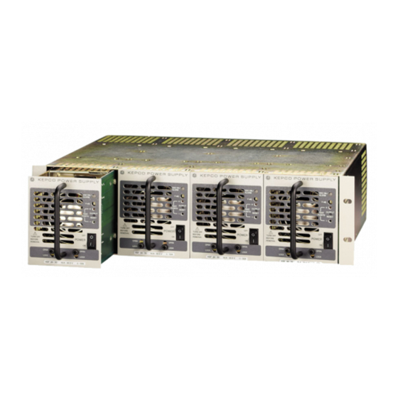
HSF 300W
POWER SUPPLY
SINGLE OUTPUT POWER SUPPLIES
UNIVERSAL AC INPUT
HSF 300W
POWER SUPPLY
HSF 5-60, HSF 12-27, HSF 15-22,
HSF 24-14, HSF 28-12, HSF 48-7
SERIAL NO.
email: hq@kepcopower.com World Wide Web: http://www.kepcopower.com
MODEL
REV. NO.
KEPCO
THE POWER SUPPLIER™
®
Advertisement
Table of Contents

Related Manuals for KEPCO HSF 5-60


Summary of Contents for KEPCO HSF 5-60
- Page 1 Data subject to change without notice. KEPCO ® ©2015, KEPCO, INC THE POWER SUPPLIER™ P/N 228-1696-r3 KEPCO, INC. 131-38 SANFORD AVENUE FLUSHING, NY. 11355 U.S.A. TEL (718) 461-7000 FAX (718) 767-1102 email: hq@kepcopower.com World Wide Web: http://www.kepcopower.com...
-
Page 2: Table Of Contents
TABLE OF CONTENTS SECTION PAGE 1. Introduction................................ 1 Scope of Manual ............................1 Description ..............................1 2. Specifications ..............................2 Features ................................. 5 DIP Switch Configuration ..........................5 Front Panel Access............................6 Keying ................................6 Output Voltage Control........................... 7 3.4.1 Front Panel Voltage Control ........................ -
Page 3: Introduction
47-440Hz). A built-in current balancing circuit and OR-ing diodes allow configuration for hot-swap and parallel-redundant N+1 operation. These power supplies are designed to be used with Kepco's Series RA 19-4C rack adapters. The RA 19-4C rack adapter accepts up to four 300W modules. All input/output connections are through a 24-pin connector that plugs in to the rack adapter. -
Page 4: Specifications
TABLE 1. HSF REAR CONNECTOR PIN ASSIGNMENTS (CONTINUED) Signal Function Name +Power Fail of open-collector alarm circuit. Used with –PF, pin 19 (see PAR. 3.7.2.2). Current Share Bus - Used whenever several power supplies are connected in parallel (see PAR. 5.). Remote Voltage - Used with REF, pin 15, for remotely controlling the output voltage (see PAR. -
Page 5: Power Rating Vs. Temperature
FIGURE 2. POWER RATING VS. TEMPERATURE TABLE 3. POWER SUPPLY RATINGS AND SPECIFICATIONS CHARACTERISTIC SPECIFICATION CONDITION/NOTES Input Voltage Nominal: 100-120V a-c, 200-240V a-c 0 to 100% load, -10 to 40°C Range: 85-265V a-c, 110-370V d-c Input Source Frequency Nominal: 50-60 Hz 0 to 100% load, -10 to 40°C At 440 Hz leakage current exceeds Range: 47-440 Hz... - Page 6 Safety: Designed to meet UL: 60950; CSA:C22.2 60950; TUV: EN60950. RoHS Compliance Contact Kepco Sales for further information. EMC Emission - Conducted: Designed to meet FCC Class B, VCCI-Class B, EN55011-B, EN55022-B EMC Emission - Radiated:...
-
Page 7: Features
B) PCB 0.063" THK FR-4 C) FRONT PANEL 0.090 THK. ALUM. 6061-T6 SEE DETAIL "A" 2. FINISH: FRONT PANEL -KEPCO DUAL TONE GRAY 3. MODULE IS KEYED AS SHOWN IN DETAIL 4. DIMENSIONS ARE IN INCHES, [DIMENSIONS IN BRACKETS 3043321 ARE IN MILLIMETERS]. -
Page 8: Front Panel Access
• Position 7 of SW1 either enables (default) or disables using the internal power supply reference voltage to power the DC ON/ALARM indicator. Position 8 of SW2 either dis- ables (default) or enables using the HSF output voltage to power the DC ON/ALARM indicator (requires minimums per Table 4 if enabled) (see PAR 3.8).Only one of these two must be enabled, the other disabled. -
Page 9: Output Voltage Control
VDC ON/ALARM Indicator V. ADJ Output Voltage Adjustment Trimmer TEST POINT (+) OUTPUT RESET switch TEST POINT (-) POWER ON/OFF switch Retaining Latches 3043322 • VDC ON/ALARM indicator. Lights green when unit is operating. When enabled by DIP switch config- uration, lights red to indicate loss of output voltage in parallel configuration only (see PAR. -
Page 10: Remote On-Off
(1) - If operating below minimums listed, see PAR. 3.7.2.2 to implement ±PF alarm signals to monitor power supply status. (2) -LED brightness of HSF 5-60 is dimmer than other models. This is normal. FIGURE 7. CONNECTIONS FOR REMOTE VOLTAGE CONTROL REMOTE ON-OFF When power is ON at the source, the output may be turned ON or OFF using the ±RC signals if... -
Page 11: Protection Circuits
“high” and 0.0 to 0.4V “low”), or a contact closure. When the ±RC pins are open, using either a mechanical switch or a high level logic signal, the HSF 300W output is cut OFF. When the ±RC pins are shorted, the output returns to within specifications. At low level logic, the maximum source current is 1.6mA and at high level the sink current is 1.0mA. -
Page 12: Undervoltage
The second option uses optically-coupled logic level alarm signals, +PF (pin 5 of the rack adapter I/O connector) and -PF (pin 13), provided directly from the Kepco RKW power supply that is the heart of the HSF. This option is selected by setting positions 5 and 6 of the DIP switches as shown in Figure 9B. -
Page 13: Vdc On/Alarm Indicator Power Options
The logic alarm circuit is a diode transistor optical coupler (see Figure 10). The transistor is nor- mally conducting. When the alarm is activated upon detection of power loss, overvoltage, fan fault, overtemperature or overcurrent condition, the transistor cuts off and the collector emitter cir- cuit is open. -
Page 14: Local/Remote Sensing
LOCAL/REMOTE SENSING HSF 300W Power Supplies allow remote error sensing which can compensate up to 0.4 Volts per load wire. Local/Remote error sensing is configured by means of separate DIP switches mounted on the RA 19-4C Rack Adapter (see RA 19-4C Rack Adapter Operator Manual). Either local or remote sensing MUST be used, otherwise the units will not operate.
Need help?
Do you have a question about the HSF 5-60 and is the answer not in the manual?
Questions and answers