Table of Contents
Advertisement
Quick Links
OPERATOR'S MANUAL
1000 AND 1500 WATT SWITCHING POWER SUPPLY
VOLTAGE/CURRENT STABILIZED DC SOURCE
KEPCO INC.
An ISO 9001 Company.
IMPORTANT NOTES:
1)
This manual is valid for the following Model and associated serial numbers:
MODEL
2)
A Change Page may be included at the end of the manual. All applicable changes and
revision number changes are documented with reference to the equipment serial num-
bers. Before using this Instruction Manual, check your equipment serial number to identify
your model. If in doubt, contact your nearest Kepco Representative, or the Kepco Docu-
mentation Office in New York, (718) 461-7000, requesting the correct revision for your par-
ticular model and serial number.
3)
The contents of this manual are protected by copyright. Reproduction of any part can be
made only with the specific written permission of Kepco, Inc.
Data subject to change without notice.
©2015, KEPCO, INC
P/N 243-0851-h
KEPCO, INC. 131-38 SANFORD AVENUE FLUSHING, NY. 11355 U.S.A. TEL (718) 461-7000 FAX (718) 767-1102
HSP SERIES
MODEL
HSP SERIES
POWER SUPPLY
ORDER NO.
SERIAL NO.
email: hq@kepcopower.com World Wide Web: http://www.kepcopower.com
REV. NO.
REV. NO.
KEPCO
THE POWER SUPPLIER™
®
Advertisement
Table of Contents

Subscribe to Our Youtube Channel
Related Manuals for KEPCO HSP Series


Summary of Contents for KEPCO HSP Series
-
Page 1: Power Supply
Data subject to change without notice. KEPCO ® ©2015, KEPCO, INC THE POWER SUPPLIER™ P/N 243-0851-h KEPCO, INC. 131-38 SANFORD AVENUE FLUSHING, NY. 11355 U.S.A. TEL (718) 461-7000 FAX (718) 767-1102 email: hq@kepcopower.com World Wide Web: http://www.kepcopower.com... -
Page 3: Table Of Contents
TABLE OF CONTENTS SECTION PAGE SECTION 1 - INTRODUCTION Scope of Manual ............................. 1-1 General Description..........................1-1 Specifications ............................1-1 Miscellaneous Features .......................... 1-5 1.4.1 Control/Programming......................... 1-5 1.4.2 Status Indicators/Flags ........................1-5 1.4.3 Setpoint Monitors:..........................1-5 1.4.4 Remote Error Sensing: ........................1-5 1.4.5 Load Sharing: ............................ - Page 4 HSP (All), Nominal Mains Voltage: Temperature Derating, ................ 1-3 HSP 1500W, Low Mains Voltage: Temperature, Power Derating............... 1-3 Outline Drawing ............................1-4 HSP Series Front Panel Controls and Indicators ..................2-1 Configuration Switch Functions ........................2-1 HSP Series Rear Panel Connections ......................2-2 Load Connection - Method I (Local Error Sensing)..................
-
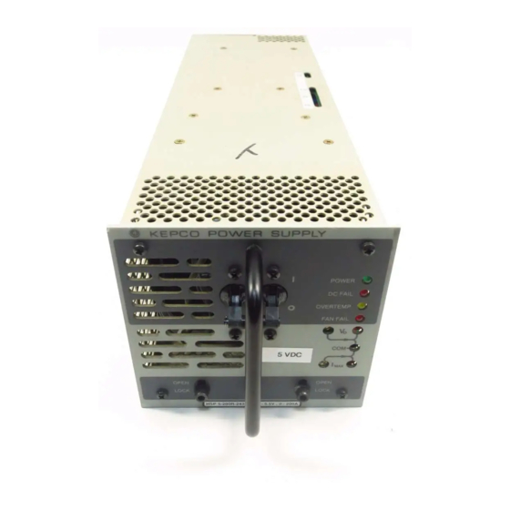
Page 6: Hsp Series Power Supply
FIGURE 1-1. HSP SERIES POWER SUPPLY HSPSERIES 081915... -
Page 7: Section 1 - Introduction
SECTION 1 - INTRODUCTION SCOPE OF MANUAL FIGURE 0-1. This manual contains instructions for the installation and operation of the HSP series of voltage and current stabilized d-c power supplies manufactured by Kepco, Inc., Flushing, New York, U.S.A. GENERAL DESCRIPTION The HSP power supply (Figure 1-1) is basically a voltage and current stabilized d-c source with a relatively sharp crossover between voltage and current mode operation. - Page 8 TABLE 1-2. GENERAL SPECIFICATIONS CHARACTERISTIC REQUIREMENT CHARACTERISTIC REQUIREMENT SOURCE INPUT OUTPUT/LOAD AC: Single-Phase, Nominal Voltage See Table 1-1. 1000W 1500W Rated Current See Table 1-1. Nominal: 100-250V rms 200-250V rms Source Voltage Range: 90-277Vrms 180-277V rms 2% of rated load (lower output conditions may Minimum Output result in increased output ripple and increased DC: 125-420V d-c (polarity insensitive)
-
Page 9: Hsp (All), Nominal Mains Voltage: Temperature Derating
TABLE 1-2. GENERAL SPECIFICATIONS (Continued) CHARACTERISTIC REQUIREMENT CHARACTERISTIC REQUIREMENT SIGNAL AND CONTROL SIGNAL AND CONTROL (CONTINUED) 3.3V & 5V Models 0.25V per wire 4.75-5.25V d-c output, 0 - 100mA, parallelable, Auxiliary Voltage Remote Error Sensing output isolated (500 V d-c), Input isolated (Isolated) All other Models 0.8V per wire... -
Page 10: Outline Drawing
FIGURE 1-4. OUTLINE DRAWING HSPSERIES OPR 081915... -
Page 11: Miscellaneous Features
MISCELLANEOUS FEATURES 1.4.1 CONTROL/PROGRAMMING VOLTAGE CHANNEL: Output voltage is controlled continuously throughout the specified adjustment range via a 10-turn potentiometer mounted behind the front panel. External control can be exercised either by resistance or by control voltage (see PAR’s. 3.3 and 3.4). CURRENT CHANNEL: Output current is controlled continuously throughout the specified adjustment range via a 10-turn potentiometer mounted behind the front panel. -
Page 12: Auxiliary Supply
1.4.7 AUXILIARY SUPPLY: Logic-level secondary output provides up to 0.5 watts of power at 5V d-c. This output is isolated from the output and is unaffected by the status of the main output. Provides power for external Remote Inhibit controls (see PAR. 3.11). 1.4.8 OVERCURRENT/UNDERVOLTAGE PROTECTION: Switch-selectable option provides the user load protection against long-term output overloads or undervoltage conditions (see PAR. - Page 13 TABLE 1-3. ACCESSORIES ACCESSORY PART NUMBER Provision for three HSP (or HSM) Power Supplies in a 19-inch rack. Used for hard-wired RACK RA 58 ADAPTERS applications only. Same as RA 60 except accommodates up to four HSP Power Supplies in a 24-inch rack for RA 59 plug-in and hot swappable applications.
-
Page 15: Section 2 - Installation
Front Panel: Refer to Figure 2-1. b) Configuration Controls: Refer to Figure 2-2 and Table 2-1. c) Rear Panel: Refer to Figure 2-3 and Table 2-1. FIGURE 2-1. HSP SERIES FRONT PANEL CONTROLS AND INDICATORS TABLE 2-1. CONFIGURATION CONTROLS FUNCTION POSITION PAR. -
Page 16: Hsp Series Rear Panel Connections
FIGURE 2-3. HSP SERIES REAR PANEL CONNECTIONS TABLE 2-1. I/O CONNECTOR PIN ASSIGNMENTS PIN NO. NAME DESCRIPTION OF FUNCTION REF. PAR. NO CONNECTION NO CONNECTION FFS-1 FAN STATUS - NORMALLY CLOSED CONTACT 3.14 ACS-C SOURCE POWER STATUS - COMMON CONTACT 3.14... -
Page 17: Source Power Requirements
1. THE POWER SUPPLY WILL NOT OPERATE UNLESS THE REMOTE SENSE LINES ARE PROPERLY CONNECTED TO THE OUTPUT TERMINALS! Connect the remote sense ter- minals to the output bus bars using the mating I/O Connector (Kepco P/N 142-0422) or other means as shown in PAR. 2.7.5.1 and Figure 2-4. -
Page 18: Installation
• When used as part of a plug-in power system, refer to the Instruction Manual accom- panying the applicable Kepco rack adapter for installation directions. For all installations, provide adequate clearance around air inlet and exhaust locations and ensure that the temperature immediately surrounding the unit and especially near the air inlets does not exceed the maximum specified ambient temperature for the operating conditions. -
Page 19: Source Power Connections
3-wire safety line cord via a polarized mating plug. Kepco offers as accessories (see Table 1-3) both a user-wired mating connector and a prewired linecord set, the latter configured for North American applications. Terminal assignment follows internationally accepted conventions (see Figure 2-3). -
Page 20: Power Supply/Load Interface
The use of the proper fastener size and inclusion of a lockwasher are critical to maintaining intimate contact between the load conductor and output bus bar; Kepco recom- mends the use of fasteners made of conductive material (brass, phosphor bronze, etc.) to enhance conductivity;... -
Page 21: Load Connection - Method I (Local Error Sensing)
2.7.5.1 LOAD CONNECTION - METHOD I (LOCAL ERROR SENSING) The most basic power supply/load interface is a 2-wire connection between the power supply output terminals and the load. This connection method employs local error sensing which con- sists of connecting the error sense leads directly to the power supply's output terminals. Its main virtue is simplicity: since voltage regulation is maintained at the power supply output, the regula- tion loop is essentially unaffected by the impedances presented by the load interconnection scheme. -
Page 22: Load Connection - Method Ii (Remote Error Sensing)
2.7.5.2 LOAD CONNECTION - METHOD II (REMOTE ERROR SENSING) If the load is located at a distance from the power supply terminals, or if reactive and/or modu- lated loads are present, remote error sensing should be used to minimize their effect on the volt- age stabilization. -
Page 23: Load Connection - Method Iii (Series Connection)
2.7.5.3 LOAD CONNECTION - METHOD III (SERIES CONNECTION) Units may be connected in series to obtain higher output voltages. Each power supply in the series should be protected by a clamping diode connected in its non-conducting direction in par- allel with the output; this diode protects the power supply outputs against secondary effects in the event of a load short. -
Page 24: Load Connection - Method Iv (Parallel Operation)
2.7.5.4 LOAD CONNECTION - METHOD IV (PARALLEL OPERATION) Identical HSP power supply models may be connected in parallel in order to provided increased output current to a common load (see Figure 2-7). This permits the user to obtain significantly higher load ratings than for a single HSP power supply. The number of power supplies required is determined by dividing the required load current by the current rating of the applicable HSP model, and rounding up to the next whole number when necessary. -
Page 25: Load Sharing
When operating power supplies in hot-swap applications, the use of an output blocking diode is mandatory to prevent excessive output transients and power connector damage due to arcing at the output terminals. In applications where redundancy is required but hot-swapping is not, the blocking diode is beneficial in that it adds a layer of isolation between each power supply output and the common d-c bus, protecting the bus against the possibility of a short at the power sup- ply output. -
Page 26: Signal Connections
HSP series plug-in rack adapters. RETAINING LATCHES HSP series power supplies are provided with (2) retention latches located at each side of the bottom edge of the front panel (see Figure 2-1). These latches work in conjunction with the HSP series plug-in rack adapters to prevent unauthorized or inadvertent module extraction from an operating power system. -
Page 27: Section 3 - Operating Instructions
The default settings for each function indicate the as-shipped status for standard HSP series power supplies. Prior to applying source power, the operating configuration of the HSP power supply must be selected. This setup is performed via the multiposition configuration... -
Page 28: Output Voltage Range
19 (VPROG, -S) of the I/O connector (see Figure 3-2). This technique is useful when imple- menting digital control of the power supply output voltage via a D/A converter; Kepco's SN/ SNR 488 programmers are ideally suited to these requirements FIGURE 3-1. -
Page 29: Current Limit Programming Range
(0-10V) connected between pins 15 and 19 (IPROG, -S) of the I/O connector (see Figure 3-3). This technique is useful when implementing digital control of the power supply current limit via a D/A converter; Kepco's SN/SNR 488 programmers are ideally suited to these requirements. -
Page 30: Overvoltage Protection Adjustment
trols (see Figure 2-1); the jacks are labeled V and I , with a third test point labeled COM providing access to the circuit return. The second location is the I/O connector: here, the test points are labeled VSET and ISET, and are available at pins 36 and 33, respectively, with circuit return accessed at pin 19 (-S) (see Figure 2-3). -
Page 31: Current Limit Characteristic
The signal generated by the OVP detector is gated with a signal from the fault detector circuit to produce a selective overvoltage shutdown function which prevents shutdown of operational power supplies in a parallel-redundant power system configuration. The OVP latches of any working power supplies are disabled, allowing only the faulty modules to be latched off;... -
Page 32: Current Walk-In Circuit
3.10 CURRENT WALK-IN CIRCUIT HSP power supplies incorporate a specialized output regulator start-up circuit for applications involving use of the HSP as a battery charger. This circuit, enabled via switch S1-2, overrides the normal duty-cycle-based soft-start circuit, which could still result in very fast output current rise rates into a discharged battery, and substitutes a controlled-current rise circuit with a time constant in accordance with Bellcore TR-TSY-000947 requirements for telecommunications bat- tery rectifiers (see Figure 3-4). -
Page 33: Remote Inhibit/Remote Reset Controls
3.12 REMOTE INHIBIT/REMOTE RESET CONTROLS HSP power supplies incorporate two TTL-level inputs, RC1 and RC2, accessed via the I/O con- nector, which can be used to disable the output regulator via external stimulus. These two con- trols operate from an internal 5V supply (5VAUX) which is isolated from both input and output (see PAR. -
Page 34: Status Indicators And Status Flags
and isolated from the ISHARE signal, so that it cannot affect the load share function if shorted. The voltage level of this signal is generated with respect to the negative sense return (pin 19). 3.14 STATUS INDICATORS AND STATUS FLAGS HSP power supplies provide both visual and electrical indication of the status of various critical functions including source power status, output status, fan status and overtemperature condi- tion;... -
Page 35: Power Indicator/Source Power Status Flags
3.14.1 POWER INDICATOR/SOURCE POWER STATUS FLAGS Monitors available source voltage to determine if sufficient energy is available to sustain rated output for normal operation. These signals indicate a fault condition until the bulk voltage is greater than 390V d-c. Once the bulk voltage reaches 390V d-c (indicating that the PFC boost converter is operating and assuring that full ride-through time is available at rated load) these signals revert to “normal”... -
Page 36: Dcfail Indicator And Output Status Flags
3.15 FRONT PANEL METER (M OPTION) OPERATION HSP series power supplies are available with a meter option (‘M' suffix) which incorporates a 3½ digit LED meter display on the front panel. The meter provides both voltmeter and ammeter functions. The V-A rocker switch directly below the meter (Figure 3-7) selects either output volt- age (V) or module current (A) as the normally-displayed parameter. -
Page 37: Voltmeter Operation
tion of the fault detector remains unaffected by the inclusion of the meter option. The following paragraphs describe the meter functions in detail. 3.15.1 VOLTMETER OPERATION With the V-A selector switch set to ‘V' position (green V indicator illuminated), the meter nor- mally displays the actual output voltage present at the error sense terminals (within ±2%). -
Page 38: Battery (B Option) Operation
The fault detector window is altered to accommodate the normal range of battery voltage from fully discharged to peak equalize charge as shown in Table 3-3.: TABLE 3-3. B OPTION FAULT DETECTION WINDOW NOMINAL BATTERY VOLTAGE KEPCO MODEL MIN. VOLTS MAX. VOLTS HSP 15-66B 10.6...
Need help?
Do you have a question about the HSP Series and is the answer not in the manual?
Questions and answers