Table of Contents
Advertisement
Quick Links
OPERATOR'S MANUAL
HSF 300W, M and MZ Models
SINGLE OUTPUT METERED POWER SUPPLIES
SINGLE PHASE, POWER FACTOR CORRECTED
KEPCO INC.
An ISO 9001 Company.
IMPORTANT NOTES:
1)
This manual is valid for the following Model and associated serial numbers:
MODEL
HSF 300W
2)
A Change Page may be included at the end of the manual. All applicable changes and
revision number changes are documented with reference to the equipment serial num-
bers. Before using this Instruction Manual, check your equipment serial number to identify
your model. If in doubt, contact your nearest Kepco Representative, or the Kepco Docu-
mentation Office in New York, (718) 461-7000, requesting the correct revision for your
particular model and serial number.
3)
The contents of this manual are protected by copyright. Reproduction of any part can be
made only with the specific written permission of Kepco, Inc.
Data subject to change without notice.
©2015, KEPCO, INC
P/N 228-1697-r4
KEPCO, INC. 131-38 SANFORD AVENUE FLUSHING, NY. 11355 U.S.A. TEL (718) 461-7000 FAX (718) 767-1102
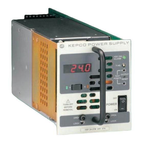
POWER SUPPLY
UNIVERSAL AC INPUT
MODEL
HSF (M, MZ) 300W
POWER SUPPLY
HSF 5-60M, HSF12-27M, HSF 15-22M,
HSF 24-14M, HSF 28-12M, HSF 48-7M
HSF12-27MZ, HSF 15-22MZ,
HSF 24-14MZ, HSF 28-12MZ, HSF 48-7MZ
SERIAL NO.
email: hq@kepcopower.com World Wide Web: http://www.kepcopower.com
REV. NO.
KEPCO
THE POWER SUPPLIER™
®
Advertisement
Table of Contents

Subscribe to Our Youtube Channel
Related Manuals for KEPCO HSF 5-60M


Summary of Contents for KEPCO HSF 5-60M
- Page 1 Data subject to change without notice. KEPCO ® ©2015, KEPCO, INC THE POWER SUPPLIER™ P/N 228-1697-r4 KEPCO, INC. 131-38 SANFORD AVENUE FLUSHING, NY. 11355 U.S.A. TEL (718) 461-7000 FAX (718) 767-1102 email: hq@kepcopower.com World Wide Web: http://www.kepcopower.com...
-
Page 2: Table Of Contents
TABLE OF CONTENTS SECTION PAGE 1. Introduction................................ 1 Scope of Manual ............................1 Description ..............................1 2. Specifications ..............................2 Features ................................. 6 DIP Switch Configuration ..........................6 Front Panel Access............................7 Keying ................................7 Output Voltage Control........................... 8 3.4.1 Front Panel Voltage Control ........................ -
Page 3: Introduction
M and MZ models, refer to the MZ model information for HSF 5-60M. The HSF M Models (except for HSF 5-60M) use the HSF output to power the VDC ON indicator, internal alarm relay, and the meter. A minimum HSF output voltage is needed to maintain function- ality for these components. -
Page 4: Specifications
TABLE 1. HSF REAR CONNECTOR PIN ASSIGNMENTS Signal Function Name Output + 1, 2, 4 DC output (+) applied to load. Output – 3, 5, 6 DC Output (–) applied to load. SENSE– Sense– connection IMON+ Current Monitor+ (sense resistor). SENSE+ Sense+ connection Normally Open contact of alarm relay, referenced to AL COM, pin 14 (see PAR. -
Page 5: Power Rating Vs. Temperature
TABLE 2. OUTPUT RATINGS AND SPECIFICATIONS HSF MODEL 5-60* 12-27* 15-22* 24-14* 28-12* 48-7* Output Volts d-c (nominal) Using front 0 to 5.5 5.5 to 13.8 7 to 17.4 7 to 28.2 7 to 33 7 to 52.2 panel trimpot 0 to 5.5 0 to 13.8 0 to 17.4... -
Page 6: Power Supply Ratings And Specifications
TABLE 3. POWER SUPPLY RATINGS AND SPECIFICATIONS CHARACTERISTIC SPECIFICATION CONDITION/NOTES Input Voltage Nominal: 100-120V a-c, 200-240V a-c 0 to 100% load, -10 to 40°C Range: 85-265V a-c, 110-370V d-c Input Source Frequency Nominal: 50-60 Hz 0 to 100% load, -10 to 40°C At 440 Hz leakage current exceeds Range: 47-440 Hz UL/VDE safety spec. - Page 7 EN61000-4-3 level 3 normal operation EMC Conducted susceptibility: EN61000-4-6 level 3 normal operation ESD: EN61000-4-2, level 4 (HSF 5-60M: level 3) normal operation Electrical fast transient burst: EN61000-4-4 level 3 normal operation Surge withstand: EN61000-4-5, level 4 (HSF 5-60M: level 3)
-
Page 8: Features
B) PCB 0.063" THK FR-4 C) FRONT PANEL 0.090 THK. ALUM. 6061-T6 SEE DETAIL "A" 2. FINISH: FRONT PANEL -KEPCO DUAL TONE GRAY 3. MODULE IS KEYED AS SHOWN IN DETAIL 4. DIMENSIONS ARE IN INCHES, [DIMENSIONS IN BRACKETS 3043284 ARE IN MILLIMETERS]. -
Page 9: Front Panel Access
• Position 7 of SW1 either enables (default) or disables using the auxiliary supply to power the DC ON indicator. Position 8 of SW2 either disables (default) or enables using the HSF output voltage to power the DC ON indicator; requires minimums per Table 4 if enabled (see PAR 3.9). -
Page 10: Output Voltage Control
VDC ON/ALARM Indicator Voltage/Current Meter V. ADJ Output Voltage Adjustment Trimmer TEST POINT (+) Meter Mode switch OUTPUT RESET switch V (Voltage) indicator TEST POINT (-) POWER ON/OFF switch A (Amperes) indicator Retaining Latches 3043129 • VDC ON/ALARM indicator. Lights green when unit is operating. Both M and MZ models permit selection of indicator power, either from HSF output or internal reference (see PAR. -
Page 11: Dip Switch Settings For Control Of Output Voltage
LED indicators, do not adjust external voltage below minimum listed in Table 4. Connect the voltage source across the RV and –COM pins as shown in Figure 7B. For MZ Models and HSF 5-60M only: The meter and relay are powered internally and are not dependent on HSF output to maintain function. -
Page 12: Vdc On/Alarm Indicator Power Options
If this occurs, turn Vadj trim pot counterclockwise to reduce output voltage, then reset the unit. TABLE 5. CONDITIONS FOR VDC ON/ALARM LED OPERATION POWERED BY OUTPUT MODEL HSF 5-60M HSF 12-53MZ HSF 15-43MZ HSF 24-27MZ HSF 28-23MZ HSF 48-13MZ... -
Page 13: Reset (Restart)
“high” and 0.0 to 0.4V “low”), or a contact closure. When the ±RC pins are open, using either a mechanical switch or a high level logic signal, the HSF output is cut OFF. When the ±RC pins are shorted, the output returns to within specifications. At low level logic, the maximum source current is 1.6mA and at high level the sink current is 1.0mA. -
Page 14: Overcurrent Setting And Protection
3.7.2 OVERCURRENT SETTING AND PROTECTION The output characteristic of the power supply is a square type, and the unit is set to produce an alarm (see PAR. 3.8.2) and shut down if output current exceeds specifications (see Table 2) for more than 30 seconds. -
Page 15: Optically-Coupled Logical Alarm
The second option uses optically-coupled logic level alarm signals, +PF (pin 5 of the rack adapter I/O connector) and -PF (pin 13), provided directly from the Kepco RKW power supply that is the heart of the HSF. This option is selected by setting positions 5 and 6 of the DIP switches as shown in Figure 10B. -
Page 16: Local/Remote Sensing
FIGURE 12. ±PF POWER FAILURE OPTOCOUPLER TIMING DIAGRAM LOCAL/REMOTE SENSING HSF (M and MZ) 300W Power Supplies allow remote error sensing which can compensate up to 0.4 Volts per load wire. Local/Remote error sensing is configured by means of separate DIP switches mounted on the RA 19-4C Rack Adapter (see RA 19-4C Rack Adapter Operator Man- ual). -
Page 17: Adjusting The Voltage
ADJUSTING THE VOLTAGE NOTE: Refer to the RA 19-4C Rack Adapter manual for alternatives to the standard master/ slave parallel configuration described below. To adjust the paralleled units, turn off all the units except one (designated as the master) and adjust to desired voltage using the front page trimmer and monitoring the front panel voltmeter. -
Page 18: Minimum Load
5.3.1 MINIMUM LOAD The minimum load (Amperes) = N x (I/10) where N = the number of units in parallel, I = Nominal current rating of individual power supply (Amperes). For applications requiring no load or lower than minimum load conditions, see voltage set restrictions of PAR. 5.3.2. Load effect specifica- tions will not be met when units are operated in redundant mode with load less than 10% per unit.
Need help?
Do you have a question about the HSF 5-60M and is the answer not in the manual?
Questions and answers