Table of Contents
Advertisement
Quick Links
OPERATOR'S MANUAL
SINGLE PHASE, UNIVERSAL AC INPUT, OPTIONAL METER
KEPCO INC.
An ISO 9001 Company.
IMPORTANT NOTES:
1)
This manual is valid for the following Model and associated serial numbers:
MODEL
HSF-A, 1500W
2)
A Change Page may be included at the end of the manual. All applicable changes and
revision number changes are documented with reference to the equipment serial num-
bers. Before using this Instruction Manual, check your equipment serial number to identify
your model. If in doubt, contact your nearest Kepco Representative, or the Kepco Docu-
mentation Office in New York, (718) 461-7000, requesting the correct revision for your par-
ticular model and serial number.
3)
The contents of this manual are protected by copyright. Reproduction of any part can be
made only with the specific written permission of Kepco, Inc.
Data subject to change without notice.
©2021, KEPCO, INC
P/N 243-1412-r4
KEPCO, INC. 131-38 SANFORD AVENUE FLUSHING, NY. 11355 U.S.A. TEL (718) 461-7000 FAX (718) 767-1102
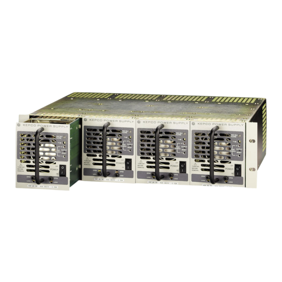
HSF-A 1500W SERIES
POWER SUPPLY
SINGLE OUTPUT POWER SUPPLIES
HSF-A 1500W SERIES
POWER SUPPLY
HSF 15-100A (C) (M), HSF 24-50A (M),
HSF 36-42A (M), HSF 48-32A (M),
SERIAL NO.
email: hq@kepcopower.com World Wide Web: www.kepcopower.com
MODEL
HSF 60-25A (M)
REV. NO.
KEPCO
THE POWER SUPPLIER™
®
Advertisement
Table of Contents

Subscribe to Our Youtube Channel
Related Manuals for KEPCO HSF-A 1500W Series


Summary of Contents for KEPCO HSF-A 1500W Series
- Page 1 Data subject to change without notice. KEPCO ® ©2021, KEPCO, INC THE POWER SUPPLIER™ P/N 243-1412-r4 KEPCO, INC. 131-38 SANFORD AVENUE FLUSHING, NY. 11355 U.S.A. TEL (718) 461-7000 FAX (718) 767-1102 email: hq@kepcopower.com World Wide Web: www.kepcopower.com...
-
Page 2: Table Of Contents
TABLE OF CONTENTS SECTION PAGE 1. Introduction ................................ 1 Scope of Manual ............................. 1 Description ..............................1 2. Specifications ..............................2 Features ................................5 DIP Switch Configuration ..........................5 Front Panel Access............................6 Keying ................................7 Output Voltage Control............................ 8 3.4.1 Front Panel Voltage Control ......................... -
Page 3: Introduction
47-63Hz). A built-in current balancing circuit and OR-ing diodes allow configura- tion for hot-swap and parallel-redundant N+1 operation. These power supplies are designed to be used with Kepco's Series RA 19-4C rack adapters. The RA 19-4C rack adapter accepts up to four modules. All input/output connections are through a 24- pin connector that plugs in to the rack adapter. -
Page 4: Specifications
Table 2 contains specifications and operating limits of individual HSF-A 1500W Series models. Table 3 contains specifications and operating limits common to all HSF-A 1500W Series Models. These specifications are at nominal input voltages at 25°C and apply to all models unless other- wise specified. -
Page 5: Power Supply Ratings And Specifications
TABLE 3. POWER SUPPLY RATINGS AND SPECIFICATIONS CHARACTERISTIC SPECIFICATION CONDITION/NOTES Input Voltage Range: 90-264V a-c, 127-370V d-c Up to t0% derating between 90 and 100V a-c Input Source Frequency Range: 47-63 Hz Input Current: 115V a-c 18A Maximum Load At 25°C with Nominal Output Voltage 230V a-c 9A Input Protection... -
Page 6: Power Rating Vs. Temperature, Load Vs. Input Voltage
TABLE 3. POWER SUPPLY RATINGS AND SPECIFICATIONS (CONTINUED) CHARACTERISTIC SPECIFICATION CONDITION/NOTES Temperature Operating: -25 to +60°·C Refer to power rating curve, Figure 3. Storage: -40 to +85°·C Humidity Operating: 20 -90% RH non-condensing Storage: 10 to 95% RH Vibration 10 -500Hz, 2G 10min./1cyc1e, period for Compliance to IEC 68-2-6, IEC 68-2-84 60min. -
Page 7: Features
B) PCB 0.063" THK FR-4 1.813" [46.04] C) FRONT PANEL 0.090 THK. ALUM. 6061-T6 SEE DETAIL "A" 2. FINISH: FRONT PANEL -KEPCO DUAL TONE GRAY 3. MODULE IS KEYED AS SHOWN IN DETAIL 4. DIMENSIONS ARE IN INCHES, [DIMENSIONS IN = PIN PRESENT 3044520 BRACKETS ARE IN MILLIMETERS]. -
Page 8: Front Panel Access
• Positions 4 and 5 - default position 4 is OFF, position 5 is ON - allows HSF output to be reset after a fault using the front panel OUTPUT RESET switch and disables remote ON/ OFF control of HSF output. (see PAR. 3.6) When position 4 is ON and position 5 is OFF, allows HSF output to be enabled/disabled via mechanical switch or logic level (see PAR. -
Page 9: Keying
Figure 3.4 shows the location of all operating controls, indicators and test points followed by an explanation of each. KEYING Keying of the power supply is established at the factory. The output voltage determines which key pins are installed (see Figure 4, Detail A). When the proper holes in the rack adapter are blocked by keying screws installed by the user, only a power supply of the correct voltage can be inserted in the rack adapter slot. -
Page 10: Output Voltage Control
OUTPUT VOLTAGE CONTROL Output Voltage can be controlled from either the front panel (PAR. 3.4.1) or externally using a trimpot or voltage source (PAR. 3.4.2). 3.4.1 FRONT PANEL VOLTAGE CONTROL Output voltage can be manually adjusted with the voltage adjustment control, Vadj (see Figure 6 for location) when DIP switch SW1 position 3 is set to ON and position 4 is set to OFF shown in Figure 5 (factory default) To adjust voltage, first place the unit under an operating load. -
Page 11: Remote On-Off
REMOTE ON-OFF When power is ON at the source, the output may be turned ON or OFF using the +RC signal if the remote ON-OFF feature is enabled. Note that when remote ON-OFF is enabled, the RESET OUT- PUT switch does not function. The unit can be reset using the remote ON-OFF feature or by leav- ing the unit OFF for at least 40 seconds Remote ON-OFF is enabled by setting DIP switch position 4 to ON and position 5 to OFF. -
Page 12: Fan Failure
3.8.2.2 OPTICALLY-COUPLED LOGICAL ALARM This ±PF signals, available in older non-A suffix HSF 1200/1500W models are not available in the HSF-A 1500W series. Therefore DIP switch SW1 position 6 should always be set to OFF and position 7 set to ON. -
Page 13: Load Connection
LOAD CONNECTION Connect the load to (+) and (–) terminals at the rear panel of the Rack Adapter. See Figure 8 for the proper way to connect multiple loads. FIGURE 8. CORRECT AND INCORRECT METHODS OF LOAD CONNECTION CONNECTING MULTIPLE POWER SUPPLIES All connections to multiple HSF-A power supplies must be made via the I/O mating connectors at rear of the Rack Adapter and/or by the Rack Adapter DIP switches.
Need help?
Do you have a question about the HSF-A 1500W Series and is the answer not in the manual?
Questions and answers