Table of Contents
Advertisement
Quick Links
Advertisement
Table of Contents

Related Manuals for Kontron KTQ67/Flex-Medical


Summary of Contents for Kontron KTQ67/Flex-Medical
- Page 1 KTQ67/Flex-Medical Users Guide KTD-N0849-C If it’s embedded, it’s Kontron...
-
Page 2: Document Revision History
Copyright 2011, KONTRON Technology A/S, ALL RIGHTS RESERVED. No part of this document may be reproduced or transmitted in any form or by any means, electronically or mechanically, for any purpose, without the express written permission of KONTRON Technology A/S. Trademark Acknowledgement: Brand and product names are trademarks or registered trademarks of their respective owners. - Page 3 KONTRON Technology warrants its products to be free from defects in material and workmanship during the warranty period. If a product proves to be defective in material or workmanship during the warranty period, KONTRON Technology will, at its sole option, repair or replace the product with a similar product.
-
Page 4: Table Of Contents
Intel® HD Graphics 3000 (example) ....................20 2.5.1 Power Consumption ........................21 Connector Locations ................. 24 KTQ67/Flex-Medical – frontside ......................24 Connector Definitions ............... 26 IO-Area Connectors ................27 Display connectors (IO Area) ......................27 DVI (lower) connector – DVI-I ......................27 5.1.1... - Page 5 KTD-N0849-C Page 5 Display connectors (Internal) ......................35 LVDS Flat Panel Connector (LVDS) (J39) (optionally) ................. 35 6.4.1 SATA (Serial ATA) Disk interface (J22 – J27) ..................36 USB Connectors (USB) ........................37 USB Connector 6/7 ........................37 6.6.1 USB Connector 8/9 (USB8/9) (J18) ....................37 6.6.2 USB Connector 10/11 (USB10/11) (J17) ..................
- Page 6 KTD-N0849-C Page 6 10 BIOS ....................61 Main .............................. 61 10.1 Advanced ............................62 10.2 10.2.1 Advanced - PCI Subsystem Settings ....................63 10.2.2 Advanced - APCI Settings ......................68 10.2.3 Advanced - Trusted Computing ...................... 69 10.2.4 Advanced - CPU Configuration ....................... 70 10.2.5 Advanced - SATA Configuration ......................
-
Page 7: Introduction
Introduction Introduction This manual describes the KTQ67/Flex-Medical made by KONTRON Technology A/S. In this manual the board will also be denoted KTQ67. The KTQ67/Flex-Medial is based on the Q67 chipset, support 2nd and 3rd generation Intel® i7 -, i5 -, i3 2Core and 4Core processor and the Celeron B810 2Core, see “Processor Support Table for more... -
Page 8: Installation Procedure
1 Installation procedure 1.1 Installing the board To get the board running, follow these steps. If the board shipped from KONTRON has already components like DRAM, CPU and cooler mounted, then relevant steps below, can be skipped. 1. Turn off the PSU (Power Supply Unit) Warning: Turn off PSU (Power Supply Unit) completely (no mains power connected to the PSU) or leave the Power Connectors unconnected while configuring the board. -
Page 9: Requirement According To Iec60950
KTD-N0849-C Page 9 Installation procedure 1.2 Requirement according to IEC60950 Users of KTQ67 should take care when designing chassis interface connectors in order to fulfil the IEC60950 standard: When an interface/connector has a VCC (or other power) pin, which is directly connected to a power plane like the VCC plane: To protect the external power lines of the peripheral devices, the customer has to take care about: •... -
Page 10: System Specification
2 System Specification 2.1 Component main data The table below summarizes the features of the KTQ67/Flex –Medical embedded motherboard. Form factor KTQ67/Flex-Medical: Flex-ATX (190,5 mm by 228,6 mm) Processor Support the following Intel® Core™ processors via Socket H2 (LGA1155), ZIF Socket •... - Page 11 KTD-N0849-C Page 11 System Specification Video Intel ® HD Graphics 4000 or Intel ® HD Graphics 3000 or Intel ® HD Graphics 2500 or Intel ® HD Graphics 2000 or Intel ® HD Graphics, depending on actual CPU. Analogue VGA and digital display ports via the Mobile Intel ® Q67 Chipset. •...
- Page 12 Dispose of used batteries according to the manufacturer’s instructions. BIOS • Kontron Technology / AMI BIOS (EFI core version) • Support for ACPI 3.0 ( Advanced Configuration and Power Interface), Plug & Play Suspend (S1 mode)
- Page 13 -20°C – 70°C; lower limit of storage temperature is defined by specification restriction of on-board CR2032 battery. Board with battery has been verified for storage temperature down to -40°C by Kontron. 5% - 95% relative humidity (non-condensing) Electro Static Discharge (ESD) / Radiated Emissions (EMI): (Pending) All Peripheral interfaces intended for connection to external equipment are ESD/ EMI protected.
-
Page 14: System Overview
KTD-N0849-C Page 14 System Specification 2.2 System overview The block diagram below shows the architecture and main components of the KTQ67. The key ® component on the board is the Intel Q67 (Cougar Point) Mobile Express Chipset. More detailed block diagram on next page. KTQ67/Flex -Medical Users Guide... - Page 15 System Specification KTD-N0849-C Page 15 Ivy Bridge or Dual Channel DDR3 Sandy Bridge PCIe x16 Graphics 1067/1333/1600 LGA1155 4 x DIMM Intel 82574L 10/100/GBe 2x DisplayPort Intel Lewisville PHY 14x USB (Gen2.0) Q67 PCH 6x SATA PCIe x4 Slot SDVO to LVDS (option) PCI slot PCI slot VIA Codec...
-
Page 16: Processor Support Table
CPU’s are indicated by text. Some processors in the list are distributed from Kontron, those CPU’s are marked by an * (asterisk). However please notice that this marking is only guide line and maybe not fully updated. Processor... - Page 17 KTD-N0849-C Page 17 System Specification Processor Clock Turbo Cores / Cache sSpec Note Step Brand [GHz] [GHz] Threads [MHz] [MB] Number [W/ºC] 2 / 4 1333/1600 3250 SR0YX 55/65.3 HDG2500 I3 3 Gen. 2 / 4 1333/1600 3245 SR0YL 55/65.3 HDG4000 (Ivy Bridge) 2 / 4...
- Page 18 Different coolers are available on the market and some is not generating any airflow or is blocking the airflow around these components, causing reduced lifetime. It is recommended to use a cooler like the Kontron PN 1046-6305 “KTQ67 Cooler”.
-
Page 19: System Memory Support
KTD-N0849-C Page 19 System Specification 2.4 System Memory support The KTQ67/Flex-Medical has four DDR3 UDIMM sockets. The sockets support the following memory features: • 4x DDR3 1.5V UDIMM 240-pin • Dual-channel with 2 UDIMM per channel • Single/dual rank unbuffered 1066/1333MT/s (PC3-8500/PC3-10600) From 256MB and up to 4x 8GB. -
Page 20: Ktq67 Graphics Subsystem
KTD-N0849-C Page 20 System Specification 2.5 KTQ67 Graphics Subsystem The KTQ67 support Intel ® HD Graphics 4000, 3000, 2500, 2000 or Intel ® HD Graphics, depending on actual CPU. However please notice that even though an Ivy Bridge CPU supporting Triple Independent Displays are used then on the KTQ67 only Dual Independent Displays are supported. -
Page 21: Power Consumption
KTD-N0849-C Page 21 System Specification 2.6 Power Consumption In order to ensure safe operation of the board, the ATX12V power supply must monitor the supply voltage and shut down if the supplies are out of range – refer to the hardware manual for the actual power supply specification. - Page 22 KTD-N0849-C Page 22 System Specification Low Power Setup results: DOS Idle, Mean, No external load Supply Current draw Power consumption +12V 0.258A 3.096W +12V P4 1.363A 16.366W 1.417A 7.083W +3V3 0.490A 1.618W -12V 0.035A 0.416W 5VSB 0.006A 0.030W Total 28.6W Windows 7, mean 3DMARK2005 (first scene) &...
- Page 23 KTD-N0849-C Page 23 System Specification High Power Setup results: DOS Idle, Mean, No external load Supply Current draw Power consumption +12V 1.978A 23.737W +12V P4 1.827A 21.924W 2.061A 10.306W +3V3 1.032A 3.404W -12V 0.032A 0.384W 5VSB 0.006A 0.030W Total 59.8W Windows 7, mean 3DMARK2005 (first scene) &...
-
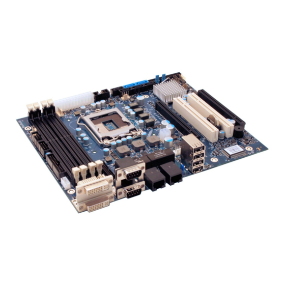
Page 24: Connector Locations
KTD-N0849-C Page 24 Connector Location 3 Connector Locations 3.1 KTQ67/Flex-Medical – frontside Sata5 - Sata0 - Sata1 Sata2 - Sata3 - Sata4 Load Default DDR3 A0 (not used) (see note) BIOS Settings ATX/ BTXPWR DDR3 A1 XDP-PCH SPI recover LVDS... - Page 25 KTD-N0849-C Page 25 Connector Location USB0 USB1 ETH2 USB2 USB3 ETH1 COM1 COM2 DVI-D DVI-I KTQ67/Flex -Medical Users Guide...
-
Page 26: Connector Definitions
KTD-N0849-C Page 26 Connector Definitions 4 Connector Definitions The following sections provide pin definitions and detailed description of all on-board connectors. The connector definitions follow the following notation: Column Description name Shows the pin-numbers in the connector. The graphical layout of the connector definition tables is made similar to the physical connectors. -
Page 27: Io-Area Connectors
5 IO-Area Connectors 5.1 Display connectors (IO Area) The KTQ67/Flex-Medical has two DVI connectors (stacked) and optionally one on-board LVDS panel interface. Both DVI connectors support single channel digital signals in a DVI-I type connector. Only the lower DVI connector support also analogue signals. Two graphic pipes are supported; meaning that up to two independent displays can be implemented using any two of the above mentioned graphic ports. -
Page 28: Dvi-D (Upper) Connector - Dvi-D
KTD-N0849-C Page 28 IO-Area Connectors 5.1.2 DVI-D (upper) connector – DVI-D The DVI-I connector is based on stacked DVI-I connector type Kycon KVI42X-DA29S-S-A4N-W or similar. It is supporting only digital signals (single channel). Pin No. Signal Description Type Pull Up TMDS Data 2- Digital Red –... -
Page 29: Ethernet Connectors (Io Area)
IO-Area Connectors 5.2 Ethernet Connectors (IO Area) The KTQ67/Flex-Medical support two channels of 10/100/1000Mb Ethernet ports, ETH1 and ETH2. Both ports are Galvanic Isolated. ETH1 (left Ethernet connector) is based on Intel® Lewisville 82579LM Gigabit PHY with AMT 8.0 support and ETH2 (right Ethernet connector) is based on Intel® Hartwell 82574L PCI Express controller. -
Page 30: Usb Connectors (Io Area)
(EHCI1 and EHCI2) that support up to fourteen USB 2.0 ports, twelve are available on the KTQ67/Flex-Medical. The USB2.0 ports allowing data transfers up to 480Mb/s and legacy Keyboard/Mouse and wakeup from sleep states are supported. Over-current detection on all fourteen USB ports is supported. -
Page 31: Com1 And Com2 Connectors (Io Area)
IO-Area Connectors 5.4 COM1 and COM2 Connectors (IO Area) Four RS232 serial ports are available on the KTQ67/Flex-Medical, COM1 and COM2 are available in the IO Area while the other COM ports are available on internal pin header connectors. The typical definition of the signals in the COM ports is as follows:... -
Page 32: Internal Connectors
KTD-N0849-C Page 32 Internal Connectors 6 Internal Connectors 6.1 Power Connector (ATX/BTXPWR) The KTQ67 board is designed to be supplied from a standard ATX (or BTX) power supply. Use of BTX supply is not required for operation, but may be required to drive high-power PCIe cards. ATX/ BTX Power Connector (J45): Note Type... -
Page 33: Fan Connectors (Fan_Cpu) (J28) And (Fan_Sys) (J29)
KTD-N0849-C Page 33 Internal Connectors 6.2 Fan Connectors (FAN_CPU) (J28) and (FAN_SYS) (J29) The FAN_CPU is used for the connection of the FAN for the CPU. The FAN_SYS can be used to power, control and monitor a fan for chassis ventilation etc. The 4pin header is recommended to be used for driving 4-wire type Fan in order to implement FAN speed control. -
Page 34: Ps/2 Keyboard And Mouse Connector (Kbdmse) (J15)
KTD-N0849-C Page 34 Internal Connectors 6.3 PS/2 Keyboard and Mouse connector (KBDMSE) (J15) Attachment of a PS/2 keyboard/mouse can be done through the pinrow connector KBDMSE (J15). Both interfaces utilize open-drain signalling with on-board pull-up. The PS/2 mouse and keyboard is supplied from SB5V when in standby mode in order to enable keyboard or mouse activity to bring the system out from power saving states. -
Page 35: Display Connectors (Internal)
KTD-N0849-C Page 35 Internal Connectors 6.4 Display connectors (Internal) The KTQ67 provides optionally internal on-board LVDS panel interface. For IO Area Display Connectors Internal Connectors (DVI-D and DVI-I), see earlier section. Two graphic pipes are supported; meaning that up to two independent displays can be implemented using any two display connectors in IO Area - and Internal (LVDS) connector (optionally). -
Page 36: Sata (Serial Ata) Disk Interface (J22 - J27)
KTD-N0849-C Page 36 Internal Connectors 6.5 SATA (Serial ATA) Disk interface (J22 – J27) The KTQ67 board has an integrated SATA Host controller (integrated in the PCH) that supports independent DMA operation on six ports. One device can be installed on each port for a maximum of six SATA devices. -
Page 37: Usb Connectors (Usb)
KTD-N0849-C Page 37 Internal Connectors 6.6 USB Connectors (USB) The KTQ67 board contains two EHCI (Enhanced Host Controller Interface) host controllers (EHCI1 and EHCI2) that support up to fourteen USB 2.0 ports allowing data transfers up to 480Mb/s. Legacy Keyboard/Mouse and wakeup from sleep states are supported. Over-current detection on all fourteen USB ports is supported. -
Page 38: Usb Connector 10/11 (Usb10/11) (J17)
KTD-N0849-C Page 38 Internal Connectors 6.6.3 USB Connector 10/11 (USB10/11) (J17) USB Ports 10 and 11 are supplied on the internal USB10/11 pinrow connector J17. Note Type Signal Signal Type Note PWR 5V/SB5V 5V/SB5V PWR USB10- USB11- USB10+ USB11+ 9 10 Signal Description USB10+ USB10-... -
Page 39: Serial Com3 - Com4 Ports (J20, J21)
KTD-N0849-C Page 39 Internal Connectors 6.7 Serial COM3 – COM4 Ports (J20, J21) Three RS232 serial ports are available on the KTQ67 via pin-row connector. (COM1 and COM2 are in the IO area and is based on standard DB9 connector, see other section for more info). The typical definition of the signals in the COM ports is as follows: Signal Description... -
Page 40: Audio Connector
KTD-N0849-C Page 40 Internal Connectors 6.8 Audio Connector The on-board Audio circuit implements 7.1+2 Channel High Definition Audio with UAA (Universal Audio Architecture), featuring five 24-bit stereo DACs and three 20-bit stereo ADCs. 6.8.1 Line2 and Mic2 Internal Connectors Line2 and Mic2 are accessible via Feature Connector, see Feature connector description. 6.8.1 Audio Header Connector (AUDIO_HEAD) (J47) Note Type Signal... -
Page 41: Power Button Connector (Pwrbtn) (J48)
KTD-N0849-C Page 41 Internal Connectors 6.9 Power Button Connector (PWRBTN) (J48) Pull Signal Type Ioh/Iol Note PWRBTN_IN# PWR_LED SLEEP_LED Signal Description PWRBTN_IN# Power Button In. Toggle this signal low to start the ATX/TX PSU and boot the board. PWR_LED PoWeR LED, active high (+5V via 470Ω). SLEEP_LED Sleep LED, active high (+5V via 470Ω). -
Page 42: Front Panel Connector (Frontpnl) (J36)
KTD-N0849-C Page 42 Internal Connectors 6.10 Front Panel Connector (FRONTPNL) (J36) Pull Ioh/ Ioh/ Pull Note Type Signal Signal Type Note PWR USB6/7_5V USB6/7_5V USB6- USB7- USB6+ USB7+ 9 10 LINE2-L 11 12 /7mA SATA_LED# 13 14 SUS_LED 15 16 PWRBTN_IN# RSTIN# 17 18... -
Page 43: Feature Connector (Feature) (J30)
KTD-N0849-C Page 43 Internal Connectors 6.11 Feature Connector (FEATURE) (J30) Pull Pull Note Ioh/Iol Type Signal Signal Type Ioh/Iol Note CASE_OPEN# SMBC /4mA 10K/ 25/25mA SMBD /4mA 10K/ 25/25mA PWR_OK EXT_BAT PWR FAN3OUT FAN3IN SB3V3 9 10 SB5V GPIO0 11 12 GPIO1 GPIO2 13 14... - Page 44 KTD-N0849-C Page 44 Internal Connectors GPIO in more details. The GPIO’s are controlled via the ITE IT8516F Embedded Controller. Each GPIO has 100pF to ground, clamping Diode to 3V3 and has multiplexed functionality. Some pins can be DAC (Digital to Analogue Converter output), PWM (Pulse Width Modulated signal output), ADC (Analogue to Digital Converter input), TMRI (Timer Counter Input), WUI (Wake Up Input), RI (Ring Indicator Input) or some special function.
-
Page 45: Load Default Bios Settings" Jumper (J11)
KTD-N0849-C Page 45 Internal Connectors 6.12 ”Load Default BIOS Settings” Jumper (J11) The “Load Default BIOS Settings” Jumper (J11) can be used to recover from incorrect BIOS settings. As an example, incorrect BIOS settings coursing no display to turn on can be erased by the Jumper. The Jumper has 3 positions: Pin 1-2, Pin2-3 (default position) and not mounted. -
Page 46: Spi Recover Jumper (J41)
KTD-N0849-C Page 46 Internal Connectors 6.14 SPI Recover Jumper (J41) The SPI Recover Jumper is used to select BIOS Recovery SPI Flash instead of the BIOS Default SPI Flash. Normally Jumper is not installed and board boots on the BIOS Default SPI Flash. Only in case the Default BIOS gets corrupted and board do not boot: Then turn off power Install Jumper (J41) -
Page 47: Spi Connector (Spi) (J40)
KTD-N0849-C Page 47 Internal Connectors 6.15 SPI Connector (SPI) (J40) The SPI Connector is normally not used. If however a SPI BIOS is connected via the SPI Connector then the board will try to boot on it. Note Pull U/D Ioh/Iol Type Signal Signal Type Ioh/Iol Pull U/D Note SB3V3... -
Page 48: Xdp-Cpu (Debug Port For Cpu) (J14)
KTD-N0849-C Page 48 Internal Connectors 6.16 XDP-CPU (Debug Port for CPU) (J14) The XDP-CPU (Intel Debug Port for CPU) connector is not mounted and not supported. XDP connector layout (pads) is located on the backside of PCB and is prepared for the Molex 52435-2671 (or 52435- 2672). -
Page 49: Xdp-Pch (Debug Port For Chipset) (J13)
KTD-N0849-C Page 49 Internal Connectors 6.17 XDP-PCH (Debug Port for Chipset) (J13) The XDP-PCH (Intel Debug Port for Chipset) connector is not mounted and not supported. XDP-PCH connector layout (pads) is prepared for the Molex 52435-2671 (or 52435-2672). Pin Signal Description Type Pull Up/Down Note HOOK0 RSMRST#... -
Page 50: Slot Connectors (Pcie, Pci)
KTD-N0849-C Page 50 Slot Connectors 7 Slot Connectors (PCIe, PCI) 7.1 PCIe Connectors The KTQ67 support one (x16) (16-lane) PCI Express port and one x4 PCI Express port (in a x16 PCI Express connector). The 16-lane (x16) PCI Express (PCIe 2.0) port can be used for external PCI Express cards inclusive graphics card. - Page 51 KTD-N0849-C Page 51 Slot Connectors PEG_RXN[4] PEG_TXP[5] PEG_TXN[5] PEG_RXP[5] PEG_RXN[5] PEG_TXP[6] PEG_TXN[6] PEG_RXP[6] PEG_RXN[6] PEG_TXP[7] PEG_TXN[7] PEG_RXP[7] CLKREQ PEG_RXN[7] PEG_TXP[8] PEG_TXN[8] PEG_RXP[8] PEG_RXN[8] PEG_TXP[9] PEG_TXN[9] PEG_RXP[9] PEG_RXN[9] PEG_TXP[10] PEG_TXN[10] PEG_RXP[10] PEG_RXN[10] PEG_TXP[11] PEG_TXN[11] PEG_RXP[11] PEG_RXN[11] PEG_TXP[12] PEG_TXN[12] PEG_RXP[12] PEG_RXN[12] PEG_TXP[13] PEG_TXN[13] PEG_RXP[13] PEG_RXN[13]...
-
Page 52: Pci-Express X4 Connector (Pcie X4) (J33)
KTD-N0849-C Page 52 Slot Connectors 7.1.3 PCI-Express x4 Connector (PCIe x4) (J33) The KTQ67 support one PCIex4 in a PCIex16 slot. All GND pins in the PCIEx16 connector are connected to GND, but all signal pins from pin 33 and above are all unconnected. Note Type Signal Signal... -
Page 53: Pci Slot Connectors
KTD-N0849-C Page 53 Slot Connectors 7.2 PCI Slot Connectors KTQ67/Flex-Medical support 2 PCI slots PCI0 – PCI1 (J1 – J2). Terminal Note Type Signal Signal Type Note -12V TRST# +12V INTA# INTB# INTC# INTD# +5V (I/O) PWR GNT3# RST# CLKB... -
Page 54: Signal Description - Pci Slot Connector
KTD-N0849-C Page 54 Slot Connectors 7.2.1 Signal Description – PCI Slot Connector SYSTEM PINS Clock provides timing for all transactions on PCI and is an input to every PCI device. All other PCI signals, except RST#, INTA#, INTB#, INTC#, and INTD#, are sampled on the risingedge of CLK and all other timing parameters are defined with respect to this edge. -
Page 55: Ktq67 Pci Irq & Int Routing
Interrupt D is used to request an interrupt and only has meaning on a multi-function device. INTD# 7.2.2 KTQ67 PCI IRQ & INT routing Board type Slot IDSEL INTA INTB INTC INTD KTQ67/Flex-Medical REQ0 GNT0 INTA INTB INTC INTD REQ1 GNT1 INTF... -
Page 56: On-Board - & Mating Connector Types
Type no. Manufacturer Type no. FAN_CPU Foxconn HF2704E-M1 1375820-4 (4-pole) FAN_SYS 1470947-1 1375820-3 (3-pole) Molex 22-23-2061 Molex 22-01-2065 KBDMSE KT 1046-3381 Kontron Foxconn HF1104E Molex 50-57-9404 CDROM Molex 70543-0038 Hon Hai LD1807V-S52T Molex 67489-8005 SATA Kontron KT 821035 (cable kit) ATXEWR... -
Page 57: System Resources
KTD-N0849-C Page 57 System Resources 9 System Resources 9.1 Memory Map Address (hex) Size (hex) Description 0xFF000000 0xFFFFFFFF 1000000 Motherboard resources 0xFEE10000 0xFEFFFFFF 1F0000 PCI bus 0xFEE00000 0xFEE0FFFF 10000 Motherboard resources 0xFED94000 0xFEDFFFFF 6C000 PCI bus 0xFED90000 0xFED93FFF 4000 Motherboard resources 0xFED40000 0xFED8FFFF 50000... -
Page 58: Pci Devices
KTD-N0849-C Page 58 System Resources 9.2 PCI Devices Device Function Vendor Device Chip Device Function 8086 0100 Intel – DRAM Controller 8086 0102 Intel - VGA Controller 8086 1C3A Q67 Chipset Intel – Management Engine 8086 1502 82579LM LAN Intel - Ethernet Controller 8086 1C2D Q67 Chipset... -
Page 59: Interrupt Usage
KTD-N0849-C Page 59 System Resources 9.3 Interrupt Usage Notes IRQ0 IRQ1 IRQ2 IRQ3 IRQ4 IRQ5 IRQ6 IRQ7 IRQ8 IRQ9 IRQ10 IRQ11 IRQ12 IRQ13 IRQ14 IRQ15 IRQ16 IRQ17 IRQ18 IRQ19 IRQ20 IRQ21 IRQ22 IRQ23 IRQ24 IRQ25 IRQ26 KTQ67/Flex -Medical Users Guide... -
Page 60: Io Map
System Resources KTD-N0849-C Page 60 9.4 IO Map Address range (hex) Size (hex) Description 0x0000F130 0x0000F137 Standard Dual Channel IDE Controller 0x0000F120 0x0000F123 Standard Dual Channel IDE Controller 0x0000F110 0x0000F117 Standard Dual Channel IDE Controller 0x0000F100 0x0000F103 Standard Dual Channel IDE Controller 0x0000F0F0 0x0000F0FF Standard Dual Channel IDE Controller... -
Page 61: Bios
4.6.5.4 Compliancy UEFI 2.3.1; PI 1.2 BIOS Version Build Date and Time 01/07/2014 13:58:49 EC Firmware Version V0.19 03/31/13 Board Information Product Name KTQ67/FLEX-Medical PCB ID Serial # 01170492 Part 64620000 Boot Count →← : Select Screen System Language [English] ↑↓... -
Page 62: Advanced
KTD-N0849-C Page 62 BIOS - Advanced 10.2 Advanced Aptio Setup Utility – Copyright © 2012 American Megatrends, Inc. Main Advanced Chipset Boot Security Save & Exit PCI Subsystem Settings PCI, PCI-X and PCI Express ► ACPI Settings Settings. ► Trusted Computing ►... -
Page 63: Advanced - Pci Subsystem Settings
KTD-N0849-C Page 63 BIOS - Advanced 10.2.1 Advanced - PCI Subsystem Settings Aptio Setup Utility – Copyright © 2012 American Megatrends, Inc. Advanced PCI Bus Driver Version V 2.05.02 Enables or Disables 64 bit capable Devices to be Decoded in Above 4G Address Space PCI 64bit Resources Handling (Only if System Supports 64 bit Above 4G Decoding... - Page 64 KTD-N0849-C Page 64 BIOS - Advanced BIOS - Advanced PCI Express Settings Aptio Setup Utility – Copyright © 2012 American Megatrends, Inc. Advanced PCI Express Device Register Settings Enables or Disables PCI Relaxed Ordering [Disabled] Express Device Relaxed Extended Tag [Disabled] Ordering.
- Page 65 KTD-N0849-C Page 65 BIOS - Advanced Function Selection Description Disabled Enables or Disables PCI Express Device Relaxed Ordering Relaxed Ordering. Enabled Disabled If ENABLED allows Device to use 8-bit Tag Extended Tag field as a requester. Enabled Disabled Enables or Disables PCI Express Device No No Snoop Snoop option.
- Page 66 KTD-N0849-C Page 66 BIOS - Advanced PCI Express GEN 2 Settings Aptio Setup Utility – Copyright © 2012 American Megatrends, Inc. Advanced PCI Express GEN2 Device Register Settings In device Functions that support Completion Timeout Completion Timeout [Default] programmability, modify the ARI Forwarding [Disabled] Completion Timeout value is...
- Page 67 KTD-N0849-C Page 67 BIOS - Advanced Function Selection Description In device Functions that support Completion Default Timeout programmability, modify the Completion Timeout range value is allowed. Completion Timeout Shorter Default: 50us to 50ms. Longer Shorter: shorter ranges supported by HW. Disabled Longer: longer ranges implemented by SW.
-
Page 68: Advanced - Apci Settings
KTD-N0849-C Page 68 BIOS - Advanced 10.2.2 Advanced - APCI Settings Aptio Setup Utility – Copyright © 2012 American Megatrends, Inc. Advanced ACPI Settings Enables or Disables BIOS APCI Auto Configuration. Enable ACPI Auto Configuration [Disabled] Enable Hibernation [Enabled] ACPI Sleep State [Both S1 and S3 avai…)] Lock Legacy Resources [Disabled]... -
Page 69: Advanced - Trusted Computing
KTD-N0849-C Page 69 BIOS - Advanced 10.2.3 Advanced - Trusted Computing Aptio Setup Utility – Copyright © 2012 American Megatrends, Inc. Advanced TPM Configuration Enables or Disables BIOS TPM Support [Enable] support for security device. O.S. TPM State [Disabled] will not show Security Device. Pending TPM operation [None] TCG EFI protocol and INT1A... -
Page 70: Advanced - Cpu Configuration
KTD-N0849-C Page 70 BIOS - Advanced 10.2.4 Advanced - CPU Configuration Aptio Setup Utility – Copyright © 2012 American Megatrends, Inc. Advanced CPU Configuration Enabled for Windows XP and Linux (OS optimized for Hyper- Intel® Pentium ® CPU G850 @ 2.90GHz Threading Technology) and CPU Signature... - Page 71 KTD-N0849-C Page 71 BIOS - Advanced Notes: Intel HT Technology (Hyper Threading Technology) is a performance feature which allows one core on the processor to appear like 2 cores to the operating system. This doubles the execution resources available to the O/S, which potentially increases the performance of your overall system. Intel VT-x Technology (Virtualization Technology) Previously codenamed "Vanderpool", VT-x represents Intel's technology for virtualization on the x86 platform.
-
Page 72: Advanced - Sata Configuration
KTD-N0849-C Page 72 BIOS - Advanced 10.2.5 Advanced - SATA Configuration Aptio Setup Utility – Copyright © 2012 American Megatrends, Inc. Advanced SATA Controller(s) [Enabled] Enable or Disable SATA Device. SATA Mode Selection [ACHI] SATA Controller Speed [Gen3] Software Feature Mask Configuration ►... - Page 73 KTD-N0849-C Page 73 BIOS - Advanced Software Feature Mask Configuration Aptio Setup Utility – Copyright © 2012 American Megatrends, Inc. Advanced RAID0 [Enabled] Enables or Disables RAID0 RAID1 [Enabled] feature. RAID10 [Enabled] RAID5 [Enabled] Intel Rapid Recovery Technology [Enabled] OROM UI and BANNER [Enabled] HDD Unlock [Enabled]...
- Page 74 KTD-N0849-C Page 74 BIOS - Advanced Submenu Software Feature Mask Configuration description: Function Selection Description Disabled RAID0 Enable or disable RAID0 feature. Enabled Disabled RAID1 Enable or disable RAID1 feature. Enabled Disabled RAID10 Enable or disable RAID10 feature. Enabled Disabled RAID5 Enable or disable RAID5 feature.
- Page 75 KTD-N0849-C Page 75 BIOS - Advanced Remaining SATA Configuration menu description: Function Selection Description Disabled Port 0 Enable or Disable SATA Port. Enabled Disabled Hot Plug Designates this port as Hot Pluggable. Enabled Disabled External SATA External SATA Support. Enabled Hard Disk Drive Identify the SATA port is connected to Solid SATA Device Type...
-
Page 76: Advanced - Intel ® Rapid Start Technology
KTD-N0849-C Page 76 BIOS - Advanced 10.2.6 Advanced - Intel ® Rapid Start Technology Aptio Setup Utility – Copyright © 2012 American Megatrends, Inc. Advanced Intel ® Rapid Start Technology [Enabled] Enable or disable Intel ® Rapid Start Technology. No valid iFFS partition found. Entry on S3 RTC Wake [Enabled] Entry After... -
Page 77: Advanced - Intel Txt (Lt) Configuration
KTD-N0849-C Page 77 BIOS - Advanced 10.2.7 Advanced - Intel TXT (LT) Configuration Aptio Setup Utility – Copyright © 2012 American Megatrends, Inc. Advanced Intel Trusted Execution Technology Configuration Enables or Disables Intel ® TXT (LT) support. Intel TXT support only can be enabled/disabled if SMX is enabled. -
Page 78: Advanced - Intel ® Anti-Theft Technology Configuration
KTD-N0849-C Page 78 BIOS - Advanced 10.2.8 Advanced - Intel ® Anti-Theft Technology Configuration Aptio Setup Utility – Copyright © 2012 American Megatrends, Inc. Advanced Intel ® Anti-Theft Technology Configuration Enables or Disables Intel ® AT in BIOS for testing only. Intel ®... -
Page 79: Advanced - Amt Configuration
KTD-N0849-C Page 79 BIOS - Advanced 10.2.9 Advanced - AMT Configuration Aptio Setup Utility – Copyright © 2012 American Megatrends, Inc. Advanced Intel AMT [Disabled] Enable/Disable Intel ® Active BIOS Hotkey Pressed [Disabled] Management Technology BIOS MEBx Selection Screen [Disabled] Extension. - Page 80 KTD-N0849-C Page 80 BIOS - Advanced Function Selection Description Set timer to wait before sending AMT Wait Timer (Note1) 0 - 65535 (Note4) ASF_GET_BOOT_OPTIONS. Disabled Disable ME (Note1) Set ME to Soft Temporary Disabled. Enabled Disabled (Note1) Enable/Disabled Alert Specification Format. Enabled Disabled Active Remote Assistance...
-
Page 81: Advanced - Acoustic Management Configuration
KTD-N0849-C Page 81 BIOS - Advanced 10.2.10 Advanced - Acoustic Management Configuration Aptio Setup Utility – Copyright © 2012 American Megatrends, Inc. Advanced Acoustic Management Configuration Option to Enable or Disable Automatic Acoustic Automatic Acoustic Management [Disabled] Management Sata Port 0 ST3120827AS Acoustic Mode [Not Available]... -
Page 82: Advanced - Usb Configuration
KTD-N0849-C Page 82 BIOS - Advanced 10.2.11 Advanced - USB Configuration Aptio Setup Utility – Copyright © 2012 American Megatrends, Inc. Advanced USB Configuration Enables Legacy USB support. AUTO option disables legacy USB Devices: support if no USB devices are 2 Hubs connected. -
Page 83: Advanced - Smart Settings
KTD-N0849-C Page 83 BIOS - Advanced 10.2.12 Advanced - SMART Settings Aptio Setup Utility – Copyright © 2012 American Megatrends, Inc. Advanced SMART Settings Run SMART Self Test on all HDDs during POST. SMART Self Test [Disabled] →← : Select Screen ↑↓... -
Page 84: Advanced - Super Io Configuration
KTD-N0849-C Page 84 BIOS - Advanced 10.2.13 Advanced - Super IO Configuration Aptio Setup Utility – Copyright © 2012 American Megatrends, Inc. Advanced Super IO Configuration Set Parameters of Serial Port 1 (COMA) Super IO Chip IT8516F Serial Port 1 Configuration ►... - Page 85 KTD-N0849-C Page 85 BIOS - Advanced Serial Port 1 Configuration Aptio Setup Utility – Copyright © 2012 American Megatrends, Inc. Advanced Serial Port 1 Configuration Enable or Disable Serial Port (COM) Serial Port [Enabled] Device Settings IO=3F8h; IRQ=4; Change Settings [Auto] →←...
- Page 86 KTD-N0849-C Page 86 BIOS - Advanced Serial Port 2 Configuration Aptio Setup Utility – Copyright © 2012 American Megatrends, Inc. Advanced Serial Port 2 Configuration Enable or Disable Serial Port (COM) Serial Port [Enabled] Device Settings IO=2F8h; IRQ=3; Change Settings [Auto] →←...
- Page 87 KTD-N0849-C Page 87 BIOS - Advanced Serial Port 3 Configuration Aptio Setup Utility – Copyright © 2012 American Megatrends, Inc. Advanced Serial Port 3 Configuration Enable or Disable Serial Port (COM) Serial Port [Enabled] Device Settings IO=3E8h; IRQ=7; Change Settings [Auto] Device Mode [Standard Serial Po…]...
- Page 88 BIOS - Advanced KTD-N0849-C Page 88 Serial Port 4 Configuration Aptio Setup Utility – Copyright © 2012 American Megatrends, Inc. Advanced Serial Port 4 Configuration Enable or Disable Serial Port (COM) Serial Port [Enabled] Device Settings IO=2E8h; IRQ=10; Change Settings [Auto] Device Mode [Standard Serial Po...]...
-
Page 89: Advanced - Voltage Monitor
KTD-N0849-C Page 89 BIOS - Advanced 10.2.14 Advanced - Voltage Monitor Aptio Setup Utility – Copyright © 2012 American Megatrends, Inc. Advanced Voltage Monitor VCore : 0.968 V 1.05 : 1.048 V : 1.512 V : 3.392 V 3.3SB : 3.392 V : 5.188 V : 12.144 V VBAT... -
Page 90: Advanced - Hardware Health Configuration
KTD-N0849-C Page 90 BIOS - Advanced 10.2.15 Advanced - Hardware Health Configuration Aptio Setup Utility – Copyright © 2012 American Megatrends, Inc. Advanced Hardware Health Configuration Disabled = Full speed. System Temperature : 30ºC/86ºF Thermal: does regulate fan System Temperature Ext : 24ºC/75ºF speed according to specified CPU Temperature... - Page 91 KTD-N0849-C Page 91 BIOS - Advanced Function Selection Description Disabled System Temperature Ext Use external connected sensor instead of Type LM75 @ 0x90 onboard. (note1) OneWire @ GPIO16 Disabled Disabled = Full speed. Fan Cruise Control Thermal (note2) Thermal: Regulate according to specified ºC. (System Fan) Speed Speed: Regulate according to specified RPM.
-
Page 92: Advanced - Lan Configuration
KTD-N0849-C Page 92 BIOS - Advanced 10.2.16 Advanced - LAN Configuration Aptio Setup Utility – Copyright © 2012 American Megatrends, Inc. Advanced LAN Configuration Control of Ethernet Devices and System UUID {f4af2da3-b59d-58a9-466cb11a02b0486f} PXE boot. To disable ETH1, ME Subsystem must be as well. ETH1 Configuration (Left) [Enabled] Wake on LAN... - Page 93 BIOS - Advanced KTD-N0849-C Page 93 Network Stack Aptio Setup Utility – Copyright © 2012 American Megatrends, Inc. Advanced Network stack [Enable] Enable/Disable UEFI network Ipv4 PXE Support [Enable] stack. Ipv6 PXE Support [Enable] Ipv6 Delay Time →← : Select Screen ↑↓...
-
Page 94: Advanced - Delay Startup
KTD-N0849-C Page 94 BIOS - Advanced 10.2.17 Advanced - Delay Startup Aptio Setup Utility – Copyright © 2012 American Megatrends, Inc. Advanced Delay startup Delay Startup →← : Select Screen ↑↓ : Select Item Enter: Select +/- : Change Opt. F1: General Help F2: Previous Values F3: Optimized Defaults... -
Page 95: Advanced - Serial Port Console Redirection
KTD-N0849-C Page 95 BIOS - Advanced 10.2.18 Advanced - Serial Port Console Redirection Aptio Setup Utility – Copyright © 2012 American Megatrends, Inc. Advanced COM0 Console Redirection Enable or Console Redirection [Disabled] Disable. Console Redirection Settings ► COM1 Console Redirection [Disabled] Console Redirection Settings ►... - Page 96 BIOS - Advanced KTD-N0849-C Page 96 Console Redirection Settings The “Console Redirection Settings” Menus are only available if related “Console Redirection” is Enabled. A different menu is available for Serial Port for Out-of-Band Management, see next page. Aptio Setup Utility – Copyright © 2012 American Megatrends, Inc. Advanced COM0 Emulation: ANSI: Extended...
- Page 97 KTD-N0849-C Page 97 BIOS - Advanced Function Selection Description Emulation: ANSI: Extended ASCII char set. VT100 VT100: ASCII char set. VT100+: Extends VT100+ Terminal Type VT100 to support color, function keys, etc. VT- VT-UTF8 UTF8: Uses UTF8 encoding to map Unicode ANSI chars onto 1 or more bytes.
- Page 98 KTD-N0849-C Page 98 BIOS - Advanced When “Serial Port for Out-of-Band Management/Windows Emergency Management Services (EMS)” > “Console Redirection” is enabled: Aptio Setup Utility – Copyright © 2012 American Megatrends, Inc. Advanced Out-of-Band Mgmt Port [COM0] Microsoft Windows Emergency Terminal Type [VT-UTF8] Management Services (EMS) Bits per second...
-
Page 99: Advanced - Cpu Ppm Configuration
KTD-N0849-C Page 99 BIOS - Advanced 10.2.19 Advanced - CPU PPM Configuration Aptio Setup Utility – Copyright © 2012 American Megatrends, Inc. Advanced CPU PPM Configuration Enable/Disable Intel SpeedStep EIST [Enabled] Turbo Mode [Enabled] CPU C3 Report [Enabled] CPU C6 Report [Enabled] CPU C7 Report [Enabled]... -
Page 100: Chipset
KTD-N0849-C Page 100 BIOS - Chipset 10.3 Chipset Aptio Setup Utility – Copyright © 2012 American Megatrends, Inc. Main Advanced Chipset Boot Security Save & Exit PCH-IO Configuration PCH Parameters ► System Agent (SA) Configuration ► →← : Select Screen ↑↓... -
Page 101: Pch-Io Configuration
BIOS - Chipset KTD-N0849-C Page 101 10.3.1 PCH-IO Configuration Aptio Setup Utility – Copyright © 2012 American Megatrends, Inc. Chipset Intel PCH RC Version 1.8.0.1 PCI Express Configuration Intel PCH SKU Name settings Intel PCH Rev ID 05/B3 PCI Express Configuration ►... - Page 102 BIOS - Chipset KTD-N0849-C Page 102 PCI Express Configuration Aptio Setup Utility – Copyright © 2012 American Megatrends, Inc. Chipset PCI Express Configuration Enable or disable PCI Express Subtractive Decode. Subtractive Decode [Enabled] Subtractive Decode Port# PCI Express Root Port 1 ►...
- Page 103 KTD-N0849-C Page 103 BIOS - Chipset PCI Express Root Port (1-2, 4-5) Aptio Setup Utility – Copyright © 2012 American Megatrends, Inc. Chipset PCI Express Root Port (1-2, 4-5) [Enabled] Control the PCI Express Root ASPM Support [Disabled] Port. PME SCI [Enabled] PCIe Speed [Auto]...
- Page 104 KTD-N0849-C Page 104 BIOS - Chipset USB Configuration Aptio Setup Utility – Copyright © 2012 American Megatrends, Inc. Chipset USB Configuration Enable or disable XHCI Pre- Boot Driver support. ECHI1 [Enabled] ECHI2 [Enabled] USB Ports Per-Port Disable Control [Disabled] →← : Select Screen ↑↓...
- Page 105 KTD-N0849-C Page 105 BIOS - Chipset PCH Azalia Configuration Aptio Setup Utility – Copyright © 2012 American Megatrends, Inc. Chipset PCH Azalia Configuration Control Detection of the Azalia device. Azalia [Auto] Disabled = Azalia will be Audio Jack Sensing [Auto] unconditionally disabled.
-
Page 106: System Agent (Sa) Configuration
KTD-N0849-C Page 106 BIOS - Chipset 10.3.2 System Agent (SA) Configuration Aptio Setup Utility – Copyright © 2012 American Megatrends, Inc. Chipset System Agent Bridge Name SandyBridge Check to enable VT-d function System Agent Bridge Name 1.8.0.0 on MCH. VT-d Capability Unsupported VT-d [Enabled]... - Page 107 KTD-N0849-C Page 107 BIOS - Chipset Graphics Configuration Aptio Setup Utility – Copyright © 2012 American Megatrends, Inc. Chipset Graphics Configuration Graphics turbo IMON current IGFX VBIOS Version 2153 values supported (14 – 31). IGFX Frequency 850 MHz Graphics Turbo IMON Current Primary Display [Auto] Internal Graphics...
- Page 108 KTD-N0849-C Page 108 BIOS - Chipset Function Selection Description Graphics Turbo IMON Graphics turbo IMON current values supported Current (14 – 31). Auto Select which of IGFX/PEG/PCI Graphics device IGFX Primary Display should be Primary Display Or select SG for Switchable Gfx.
- Page 109 BIOS - Chipset KTD-N0849-C Page 109 LCD Control Aptio Setup Utility – Copyright © 2012 American Megatrends, Inc. Chipset LCD Control Select the Video Device which will be activated during POST. Primary IGFX Boot Display [VBIOS Default] This has no effect if external LCD Panel Type [VBIOS Default] graphics present.
- Page 110 KTD-N0849-C Page 110 BIOS - Chipset Function Selection Description Select the Video Device which will be VBIOS Default activated during POST. (DVI-A, default 1) This has no effect if external graphics (DVI-D, default 1) present. Primary IGFX Boot Display (LVDS display) Secondary boot display selection will EFP3 (DP2 display)
- Page 111 KTD-N0849-C Page 111 BIOS - Chipset Function Selection Description VBIOS Default NTSC_M NTSC_M_J NTSC_433 PAL_B PAL_G PAL_D PAL_H PAL_I PAL_M PAL_N SECAM_L Select the ability to configure a TV1 Standard SECAM_B TV Format. SECAM_D SECAM_G SECAM_H SECAM_K HDTV_STD_SMPTE_240M_1080i59 HDTV_STD_SMPTE_240M_1080i60 HDTV_STD_SMPTE_295M_1080i50 HDTV_STD_SMPTE_295M_1080p50 HDTV_STD_SMPTE_296M_720p50 HDTV_STD_SMPTE_296M_720p60...
- Page 112 KTD-N0849-C Page 112 BIOS - Chipset Function Selection Description Valid only for ACPI. Legacy = ALS Support through the IGD INT10 Enabled ALS Support function. Disabled SCPI = ALS support through an ACPI ALS driver. Select the Active LFP Configuration. No LVDS: VBIOS does not enable LVDS.
- Page 113 KTD-N0849-C Page 113 BIOS - Chipset DMI Configuration Aptio Setup Utility – Copyright © 2012 American Megatrends, Inc. Chipset DMI Configuration Enable or disable DMI Vc1. X4 Gen2 DMI Vc1 Control [Enabled] DMI Vcp Control [Enabled] DMI Vcm Control [Enabled] DMI Link ASPM Control [L0sL1] DMI Extended Synch Control...
- Page 114 BIOS - Chipset KTD-N0849-C Page 114 NB PCIe Configuration Aptio Setup Utility – Copyright © 2012 American Megatrends, Inc. Chipset NB PCIe Configuration Configure PEG0 B0:D1:F0 PEG0 Not Present Gen1-Gen3 PEG0 – Gen X [Auto] PEG0 ASPM [Disabled] Enable PEG [Auto] Detect Non-Compliance Device [Disabled]...
- Page 115 KTD-N0849-C Page 115 BIOS - Chipset Function Selection Description Auto Configure PEG0 B0:D1:F0 PEG0 – Gen X GEN1 Gen1-Gen3 Gen2 Disabled Auto Control ASPM support for the PEG: Device 1 PEG0 ASPM ASPM L0s Function 0. This has no effect if PEG is not the currently active device.
- Page 116 KTD-N0849-C Page 116 BIOS - Chipset Memory Configuration Aptio Setup Utility – Copyright © 2012 American Megatrends, Inc. Chipset Memory Information Select DIMM timing profile that should be used. Memory RC Version 1.8.0.0 Memory Frequency 1333 Mhz Total Memory 8192 MB (DDR3) DIMM#0 4096 MB (DDR3) DIMM#1...
- Page 117 KTD-N0849-C Page 117 BIOS - Chipset Table continued: Function Selection Description Dynamic 1 GB 1.25 GB 1.5 GB Maximum Value of TOLUD. 1.75 GB Dynamic assignment would adjust TOLUD Max TOLUD 2 GB automatically based on largest MMIO length of installed graphic controller.
- Page 118 KTD-N0849-C Page 118 BIOS - Chipset Memory Thermal Configuration Aptio Setup Utility – Copyright © 2012 American Megatrends, Inc. Chipset Memory Thermal Configuration Enable or disable Memory Thermal Management. Memory Thermal Management [Enabled] →← : Select Screen ↑↓ : Select Item Enter: Select +/- : Change Opt.
- Page 119 KTD-N0849-C Page 119 BIOS - Chipset GT – Power Management Control Aptio Setup Utility – Copyright © 2012 American Megatrends, Inc. Chipset GT – Power Management Control Check to enable render GT Info GT1 (0x102) standby support. RC6 (Render Standby) [Enabled] RC6+(Deep RC6) [Enabled]...
-
Page 120: Boot
BIOS - Boot KTD-N0849-C Page 120 10.4 Boot Aptio Setup Utility – Copyright © 2012 American Megatrends, Inc. Main Advanced Chipset Boot Security Save & Exit Boot Configuration Number of seconds to wait for Setup Prompt Timeout setup activation key. Bootup NumLock State [On] means indefinite... - Page 121 KTD-N0849-C Page 121 BIOS - Boot Function Selection Description Number of seconds to wait for setup activation key. Setup Prompt Timeout 1, 2 - 65535 (Note) 65535 (0xFFFF) means indefinite waiting. Bootup NumLock State Select the Keyboard Numlock state. Disabled Quit Boot Enables or disables Quiet Boot option.
-
Page 122: Csm16 Parameters
KTD-N0849-C Page 122 BIOS - Boot 10.4.1 CSM16 parameters Aptio Setup Utility – Copyright © 2012 American Megatrends, Inc. Main Advanced Chipset Boot Security Save & Exit CSM16 Parameters UPON REQUEST – GA20 can be disabled using BIOS CSM16 Module Version 07.70 services. -
Page 123: Force Boot Setup
KTD-N0849-C Page 123 BIOS - Boot 10.4.2 Force Boot Setup Aptio Setup Utility – Copyright © 2012 American Megatrends, Inc. Main Advanced Chipset Boot Security Save & Exit Force Boot Setup This option controls if CSM will be launched. Force Boot [Enabled] Boot [Sata Port]... -
Page 124: Csm Parameters
KTD-N0849-C Page 124 BIOS - Boot 10.4.3 CSM parameters Aptio Setup Utility – Copyright © 2012 American Megatrends, Inc. Main Advanced Chipset Boot Security Save & Exit Launch CSM [Enabled] This option controls if CSM Boot option filter [UEFI and Legacy] will be launched. -
Page 125: Security
KTD-N0849-C Page 125 BIOS -Security 10.5 Security Aptio Setup Utility – Copyright © 2012 American Megatrends, Inc. Main Advanced Chipset Boot Security Save & Exit Password Description Set Administrator Password If ONLY the Administrator’s password is set, then this only limits access to Setup and is only asked for when entering Setup. -
Page 126: Hdd Security Configuration
KTD-N0849-C Page 126 BIOS -Security 10.5.1 HDD Security Configuration Aptio Setup Utility – Copyright © 2012 American Megatrends, Inc. Main Advanced Chipset Boot Security Save & Exit HDD Password Description : Set HDD User Password. Allows Access to set, Modify and Clear *** Advisable to Power Cycle HardDisk User and Master Passwords. -
Page 127: Save & Exit
BIOS – Save & Exit KTD-N0849-C Page 127 10.6 Save & Exit This Menu is special; having no “selections” for each function, or in other words, the function is the same as the selection. Aptio Setup Utility – Copyright © 2012 American Megatrends, Inc. Main Advanced Chipset Boot Security Save &... -
Page 128: Ami Bios Beep Codes
BIOS – Beep/POST 11 AMI BIOS Beep Codes It is normal for Kontron AMI UEFI BIOS to generate some beeps after POST has passed successfully: The first beep indicates that POST has successfully passed. Then a number of beeps indicate the number of attached USB devices. -
Page 129: Os Setup
KTD-N0849-C Page 129 OS Setup 12 OS Setup Use the Setup.exe files for all relevant drivers. The drivers can be found on KTQ67 Driver CD or they can be downloaded from the homepage http://www.kontron.com/ KTQ67/Flex -Medical Users Guide...
Need help?
Do you have a question about the KTQ67/Flex-Medical and is the answer not in the manual?
Questions and answers