Table of Contents
Advertisement
Quick Links
SPECIFICATIONS
120/230 (Single Phase L-N)/277/347 VAC, 50/60 Hz; Load Requirements: @120VAC, 0 - 1000VA, 1/4 HP, @230VAC, 0 - 1000 VA, @277VAC, 0 - 1200VA, 1/4 HP; Tungsten, Ballasts, Electronic Ballast, Fluorescent and LED;
@347V, 0 - 1500 VA, 1/4 HP; Ballasts and LED; Light Level: 1-300 fc (@4000K), Factory Default: 300 fc; Time Delay Adjustment: 1-30 minutes (Remote), 5-30 minutes (Manual Trimpot), Factory Default: 15 minutes, Senstivity:
Min, Med, Max, Factory Default : Max
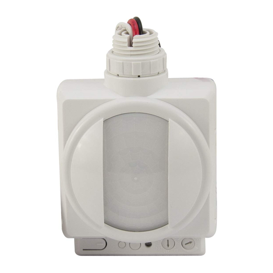
DESCRIPTION AND OPERATION
The HBP series occupancy sensors are designed for automatic lighting control in
warehouse high bay applications. All models contain a passive infrared sensor (PIR). The
coverage area is determined by the selected lens module. The lenses are interchangeable
with any HBP series sensor.
HBP-111
The HBP-111 can be commissioned remotely using the FSIR-100 or with the manual trimpot
settings.
HBP-112
The HBP-112 can be commissioned manually by adjusting the trimpots designated for Time
Delay and Light Level settings.
Product Dimensions
1.64in
41.75mm
.66in
16.70mm
2.75in
69.92mm
.22in
5.53mm
1.09in
27.75mm
LENS COVERAGE
The HBP-111/112 occupancy sensors are modular,
consisting of two parts, a Sensor Module and a Lens.
When used with the HBP-L7 lens, the sensors are
optimal for mounting heights of 20' to 40'. There is an
optional masking accessory for aisle way applications.
Snap it on and rotate to the desired position.
Lens and sensors are indoor rated and are ideal for
warehouse spaces. Avoid placing the sensor where
shelving or other obstructions may block the sensor's
line of sight.
Passive Infrared Sensing in Warehouses
Warehouses can have ambient temperature variations that may affect sensor detection
and coverage areas. High temperatures at the covered area (above 80°F) reduce the
detection zone of the sensor. Consider adding more sensors if the ambient temperatures
are expected to be high. Additionally, high floor level temperature may require larger
movement for detection. In some cases, sensors mounted above 40' may only detect large
heat signatures such as forklift trucks. See the Best Practices Guide for Warehouse at
www.wattstopper.com for more information.
HBP‑L7: 360° Coverage
The HBP-L7 has a lens that covers a 100' diameter area at a height of 40'.
Coverage Top View @ 40'
50'
25'
100'
0'
25'
50'
50'
25'
0'
25'
50'
0'
15'
27'
40'
50'
40'
30'
20'
10'
0'
10'
20'
30'
40'
Standard Coverage Side View
READ AND SAVE THESE INSTRUCTIONS
To be installed by a certified electrician or other qualified person.
WARNING – To prevent severe shock or electrocution, always turn
power off at the service panel before installing this unit, working on the
circuit, or changing a lamp.
2.75in
69.97mm
2.36in
60mm
3.23in
81.97mm
Coverage Top View @ 40' with Masking
50'
25'
0'
25'
50'
50'
25'
0'
25'
0'
15'
27'
40'
50'
40'
30'
20'
10'
0'
10'
20'
50'
Side View with Masking
HBP-111/HBP-112
High Bay • Line Voltage • Passive Infrared Occupancy Sensor
MOUNTING OPTIONS
The HBP series sensors can be attached to a fixture or junction box using the
attached nipple. The optional extender module (HBP-EM1) can be used to lower the
sensor by up to 4 inches. The extender module provides several mounting height
options through the use of simple knock outs. Refer to the HBP-EM1 installation
instructions for further details.
Using the Attached Nipple
With Nipple
Nipple
Using the HBP‑EM1 Extender Module
Nipple
INSTALLATION
TURN POWER OFF AT THE CIRCUIT BREAKER BEFORE
WORKING WITH OR NEAR HIGH VOLTAGE.
1.
Determine the mounting location appropriate to the features of the sensor and the
coverage area. Careful consideration must be given to sensor placement. Avoid placing
the sensor where the edge of the fixture, shelving or other obstructions may block the
sensor's line of sight. Mount the sensor below the edge of the fixture and away from the
fluorescent lamps so that the heat from the lamps does not affect the sensor.
2.
Make sure that you have the appropriate accessories for the sensor mounting
configuration. (See Mounting Options.)
3.
Assemble any necessary mounting accessories and attach them to the sensor, making
sure that the flying leads from the power module are accessible.
4.
Connect the line voltage and load wires to the sensor leads as shown in the Wiring
Diagram for the unit's application.
•
Do not allow bare wire to show.
•
Make sure all connections are secure.
5.
Restore power from the circuit breaker.
WIRING
100'
50'
Red
Load
30'
40'
50'
Threaded nut
Threaded nut
Extender module
CAUTION
ADJUSTMENTS
Push Button
IR
IR
Transmitter
Receiver
Black
Note: IR remote commissioning on
Hot
White
HBP-111 only
Neutral
PIR Sensor
(do not touch)
Light Level
Adjustment
Trimpot
Time Delay
Detection
Adjustment
Indicator LED
Trimpot
Advertisement
Table of Contents

Related Manuals for wattstopper HBP-111


Summary of Contents for wattstopper HBP-111
- Page 1 HBP series sensor. options through the use of simple knock outs. Refer to the HBP-EM1 installation instructions for further details. HBP-111 The HBP-111 can be commissioned remotely using the FSIR-100 or with the manual trimpot Using the Attached Nipple settings. With Nipple...
- Page 2 WARRANTY INFORMATION WattStopper warranties its products to be free of defects in materials and workmanship for a period of five (5) years. There are no obligations or liabilities on the part of WattStopper for consequential damages arising out of or in connection with the use or performance of this product or other indirect damages with respect to loss of property, revenue, or profit, or cost of removal, installation or reinstallation.
Need help?
Do you have a question about the HBP-111 and is the answer not in the manual?
Questions and answers