Table of Contents
Advertisement
Quick Links
Download this manual
See also:
User Manual
Installation Guide
support@fingertec.com
3
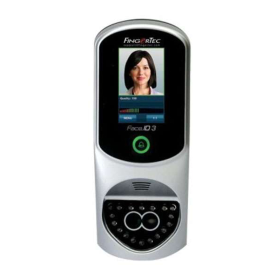
Face ID3
Face Recognition System for Door Access
w w w . f i n g e r t e c . c o m
Step 1
Determine the Location and Positioning
of the Installation
•
Avoid installing the terminals in locations that has contact with
a strong light source (e.g direct sunlight, spotlight, fluorescent
light, etc)
•
Avoid installing the terminals in locations with high moisture or
condensation levels in the air
•
The recommended installation height of the terminal from the
ground is 1.2 meters.
Step 2
Mounting of Terminals on a Wall
support@fingertec.com
Back Plate
3
4 feet / 1.2 meter
(recommended)
•
After determining the height of the terminal from the ground
level and have made the relevant marks on the wall, drill the
screws into the wall to fix the back plate.
Refer to Appendix II for dimensions and measurements of instal-
lation.
INSTALLATION TIPS:
A good installation location of Face ID
3 must
1 - Avoid sunlight.
2 - 2 meters away from any light source
e.g. ceiling direct flourescent light
3 - Suggested 1.2m from the ground level
(measure from ground to the camera)
Step 3
Wiring for Power Supply
Use power cables (black and red) to connect to a linear power sup-
ply with specifications of 12VDC 3A (Marked A).
POWER
SUPPLY (A)
GND
+12V
DC12V 3A
Power Supply
RS232/RS485 SERIAL PORT
1. RS485 Single Connection
485-
485+
485+
485-
GND
TXD
RS232
2. RS485 Network Connection
RXD
cable
485+
GND
485-
WD1
485+
3rd party controller
with 26 bits wiegand
WD2
485-
input
Door Lock connector. Refer to Appendix I
TCP/IP PORT
RJ45-1
RJ45-2
RJ45-3
RJ45-6
TCP/IP
BEEP
GLED
RLED
INWD0
INWD1
GND
+12V
3rd party
controller
with 26 bit
wiegand output
RX+
RX-
RS232/RS485
Data Converter
RX+
RX-
RS232/RS485
Data Converter
Advertisement
Table of Contents

Related Manuals for FingerTec Face ID3


Summary of Contents for FingerTec Face ID3
-
Page 1: Installation Guide
Power Supply BEEP GLED RLED INWD0 INWD1 support@fingertec.com Back Plate +12V 3rd party Face ID3 controller with 26 bit wiegand output Face Recognition System for Door Access RS232/RS485 SERIAL PORT 4 feet / 1.2 meter 1. RS485 Single Connection (recommended) 485-... - Page 2 110~240VAC switching linear power. The AdapTec Plus supplies connect to the communication port of the terminal. Select wires 12VDC power to the FingerTec terminal and door lock system as with label RX, TX and GND, and connect the other end of these well as charges a 12VDC 7.0Ah backup battery simultaneously.
- Page 3 Appendix I Appendix II Power Supply & Door Lock System Wiring Diagrams Terminal Dimensions and Measurements Door Lock Connectors Diagram1 • Normally Close (NC) WIRING PORT USAGE 25 mm BELL- BELL- To connect to schedule bell/siren BELL+ BELL+ Door Sensor (SEN-GND) Release Release Button (BUT-GND) Button...
Need help?
Do you have a question about the Face ID3 and is the answer not in the manual?
Questions and answers