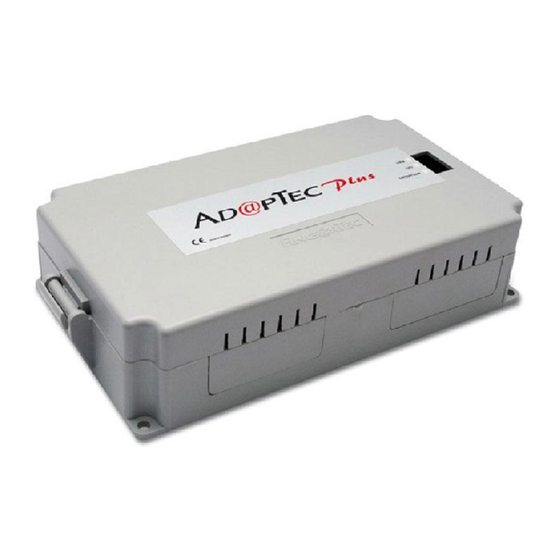
Summary of Contents for FingerTec AdapTec Plus
- Page 1 Installer Guide...
- Page 2 Power Up Terminals & Door Lock Systems A single AdapTec Plus can support a maximum of 2 units of FingerTec terminals and 2 sets of door lock accessories such as the EM lock and drop bolt in one single system installation.
- Page 3 Seamless Integration with FingerTec Terminals Mix and match the FingerTec terminals via AdapTec Plus for a cost effec- tive access control system suitable for small and medium sized offices. UNDERSTANDING THE TECHNICAL SPECIFICATIONS...
- Page 4 These cables connect to a 12VDC rechargeable backup battery. During a power failure, the backup battery will power up AdapTec Plus. These are the power output ports from AdapTec Plus. Refer to the wiring diagram for details. These are the Wiegand data input ports from the FingerTec terminals. Refer...
-
Page 5: Other Features
• Over Voltage (Non-stop buzzing after startup) Over voltage of power input (Stop the power supply to the system immedi- ately and check the input voltage, consult support@fingertec.com) Adjust the door lock timer for a longer or shorter unlocking time period by turning the screw clockwise. - Page 6 Please make sure you are using the following FingerTec models that support the encrypted 26-bit Wi- egand signal to work with the AdapTec Plus to setup a door lock system: WelcomeCheck-In 01-01 09:00...
- Page 7 WIRING DIAGRAMS CoNveNIeNT INSTAllATIoN AdapTec Plus Tamper Siren +12V Siren Exit Data Switch Lock Mute Switch Exit Button Lock Emergency 3 Break Glass Connection Points Emergency 2 Break Glass WIRING DIAGRAMS SeCURe INSTAllATIoN AdapTec Plus Tamper Siren +12V Siren Exit...
-
Page 8: Alarm Siren
Benefi ts of Using AdapTec Plus with Alarm Siren We recommend that you install a terminal along with AdapTec Plus if you plan to use the alarm siren. In AdapTec Plus, an additional port is read- ily built to receive the alarm signal from the FingerTec terminals. AdapTec Plus has an output of 12VDC and it is suitable for use with an alarm siren that has the same power input. - Page 9 Turn Off Alarm to turn off the alarm siren. 2. To deactivate the alarm siren of Adaptec Plus, press the Siren Mute Button that is connected to the Adaptec Plus. This will turn off the alarm siren function in the Adaptec Plus.
- Page 10 4 feet / 1.2 meter (recommended) To install FingerTec AC900/R2 on a wall, drill 5 holes as shown. 4 small holes are for the screws and the bigger hole is for the network cable. Tighten the 4 screws to fix the Back Steel Plate on the wall.
- Page 11 Glass Doorframe U-Bracket Allen Key Screws Steel Allen Key Philip Screw Screws Glass Door Lodge the U-Bracket into the upper edge of the glass doorframe. Tighten the 4 Allen Key Screws to hold the U-Bracket into position. Place the Steel Bar on the side of the U-Bracket.
- Page 12 OVERVIEW OF THE WHOLE SYSTEM INSTALLATION Switching power supply AC110/240V 12VDC Power Input 12VDC Rechargeable battery ABOVE CEILING CEILING ON-OFF Keyswitch EM Lock Emergency Break Glass Hub/Switch MENU FingerTec Push Button Terminal OUTDOOR INDOOR NETWORKING...
- Page 13 MOUNTING AN ADAPTEC PLUS ONTO A WALL Mount the AdapTec Plus on a wall Identify a location to mount the AdapTec Plus on a wall. Fix the AdapTec Plus onto the wall by tightening the screws into the 4 holes.
- Page 14 NOTE: Details in this user guide are subject to change. Check http://product.fingertec.com for latest product information. © 2000-2013 FingerTec Worldwide Sdn. Bhd. All rights reserved. • Printed in Malaysia. 102013...


Need help?
Do you have a question about the AdapTec Plus and is the answer not in the manual?
Questions and answers