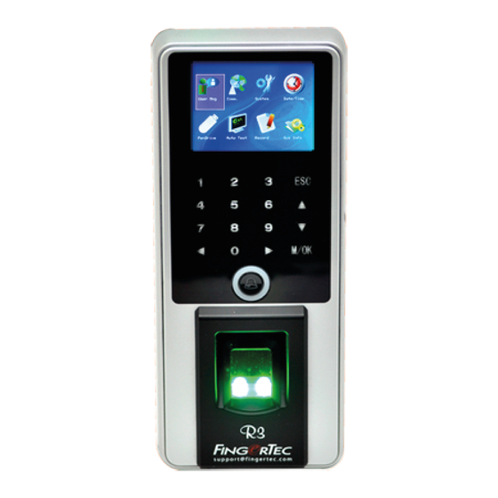
FingerTec R3 Installation Manual
Fingerprint color door access & time attendance
Hide thumbs
Also See for R3:
- Quick start manual (5 pages) ,
- Quick start manual (2 pages) ,
- User manual (28 pages)
Advertisement
Quick Links
Installation Guide
R3
Fingerprint Color Door Access &
Time Attendance
© 2014 Timetec Computing Sdn Bhd. All rights reserved.• 102014
Step 1
Determine the Location and Position
of the Installation
•
Avoid installing the terminals in locations that have contact with
a strong light source (e.g direct sunlight, spotlight, fluorescent
light, etc)
•
Avoid installing the terminals in locations prone to high moisture
or condensation levels in the air
•
The recommended installation height of the terminals from the
ground is 1.2 meter.
Step 2
Mounting Terminals
It is recommended that the terminals be mounted to a wall in
to ease the process of enrolment and verification. In a situation
whereby mounting the terminals on a wall is not an option, you
can choose to use flexi kit to convert the terminals to desktop units.
However, there are limited options for the flexi kit and some termi-
nals might not be suitable to be placed on flexi kits.
A. MOUNT ON WALL
•
After measuring the height
accordingly and make rel-
evant marking on the wall,
drill the screws into the wall
to secure the back plate.
•
Attach the terminal to the
back plate and tighten the
screws. Refer to Appendix I
for dimensions and meas-
4 feet / 1.2 meter
urements of installation.
(recommended)
Step 3
Wiring for Power Supply
The power input ports for this model are located at the rear of the
terminal. There is no adapter plug supplied with the model, you
need to source for power cable (red and black cables) to connect
the power from the terminal to the AdapTec.
TCP/IP
3rd party controller
with 26 bits
Wiegand output
WD0
WD1
GND
RXD
For NC or NO door lock system
TXD
GND
485+
485 _
DC12V
Power Supply
1. RS485 Single Connection
2. RS485 Network Connection
485+
RX+
485+
RX+
485 _
RX _
485 _
RX _
RS232/RS485
RS232/RS485
485+
Data Converter
Data Converter
485 _
3rd party controller
with 26 bits
Wiegand input
RS232
cable
Advertisement

Related Manuals for FingerTec R3


Summary of Contents for FingerTec R3
- Page 1 Step 3 Step 1 Wiring for Power Supply Determine the Location and Position of the Installation The power input ports for this model are located at the rear of the • terminal. There is no adapter plug supplied with the model, you Avoid installing the terminals in locations that have contact with need to source for power cable (red and black cables) to connect a strong light source (e.g direct sunlight, spotlight, fluorescent...
- Page 2 The AdapTec supplies 12VDC power to the label RX, TX and GND, and connect the other end of these wires to a FingerTec terminal and door lock system as well as charges a 12VDC Emergency Key switch...
- Page 3 Appendix I Door Lock Connectors Terminal Dimensions and Measurements WIRING USAGE PORT Dry Contact (independ-ent power supply for door lock) 17mm 17mm • NO type door lock (NO-COM) 78 mm • NC type door lock (NC-COM) Power Contact (using power from terminal to power on door lock) •...
Need help?
Do you have a question about the R3 and is the answer not in the manual?
Questions and answers