Honeywell Lynx Plus Programming Manual
Hide thumbs
Also See for Lynx Plus:
- Installation and setup manual (80 pages) ,
- User manual (64 pages) ,
- Quick manual to user functions (2 pages)

Related Manuals for Honeywell Lynx Plus


Summary of Contents for Honeywell Lynx Plus
-
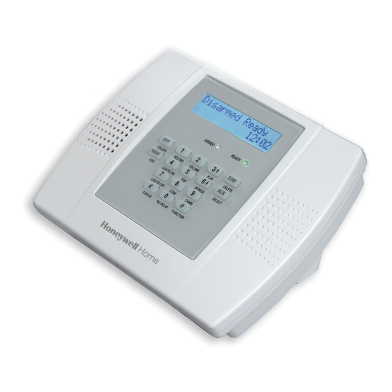
Page 1: Security System
Lynx Plus Security System Programming Guide ARMED READY STAY ESCAPE RECORD VOLUME PLAY DELETE AWAY LIGHTS ON TEST BYPASS SELECT LIGHTS OFF CODE CHIME STATUS NO DELAY FUNCTION 800-03859 9/09 Rev. A... -
Page 2: Table Of Contents
5800 Series Transmitter Loop Numbers Diagram ....................21 Lynx Plus Summary of Connections Diagram......................23 Refer to the Lynx Plus Series Installation and Setup Guide P/N 800-03858 or later for detailed information on programming the system. The Installation and Setup Guide contains full descriptions for all data fields. -
Page 3: To Exit Programming Mode
To Initialize Download ID and Subscriber Account Number for Downloading: 96 Resets all subscriber account numbers and CSID in preparation for an initial download. ✻ To Load a Default Set: 97 Enter a number 1-4 corresponding to the selected default table (See the Installation Instructions for the ✻... - Page 4 Data Field Display Function& Programming Options [ ] = Programmed Table 1 Default Values Daylight Saving Time Start/End Weekend 30 30 30 30 [2,1] DST WEEK WEEK STR/END STR/END WEEK WEEK STR/END STR/END Start 0=disable; 1=first; 2=second; 3=third; 4=fourth; 5=last; 6=next to last; 7=third from last ZONE SOUNDS AND TIMING (✻31–...
- Page 5 Data Field Display Function& Programming Options [ ] = Programmed Table 1 Default Values Primary Phone Number 41 41 41 41 PRIMARY PRIMARY PRIMARY PRIMARY TEL TEL NUM Enter up to 20 digits; Do not fill unused spaces. If fewer than 20 digits entered, pressing ✻advances to the next field.
- Page 6 Data Field Display Function& Programming Options [ ] = Programmed Table 1 Default Values Split/Dual Reporting 49 49 49 49 SPLIT/DUAL SPLIT/DUAL REP SPLIT/DUAL SPLIT/DUAL To Primary Phone No. To Secondary Phone No. 0 = All reports None, unless primary fails, then all 1 = Alarms, Restore, Cancel Others 2 = All except Open/Close, Test...
- Page 7 Data Field Display Function& Programming Options [ ] = Programmed Table 1 Default Values TO PROGRAM SYSTEM STATUS, & RESTORE REPORT CODES (✻59–✻76, & ✻89): With a 3+1 or 4+1 Standard Format: Enter a code in the first box: 1–9, 0, B, C, D, E, or F. Enter "#+10" for 0, "#+11" for B, "#+12"...
- Page 8 Data Field Display Function& Programming Options [ ] = Programmed Table 1 Default Values Bypass Restore Report Code 72 72 72 72 [0,0] BYPASS BYPASS BYPASS BYPASS RES RES REP AC Restore Report Code 73 73 73 73 [0,0] AC AC AC AC RESTORE RESTORE RESTORE REP RESTORE...
- Page 9 Data Field Display Function& Programming Options [ ] = Programmed Table 1 Default Values Event Log 80% Full Report Code 89 89 89 89 [0,0] EVNT EVNT LOG LOG 80% 80% REP EVNT EVNT Event Logging Note: System messages are logged when 90 90 90 90 any non-zero selection is made.
-
Page 10: Enhanced Zone Programming
✻ ✻ ✻ ✻ 56 ENHANCED ZONE PROGRAMMING PROCEDURE This interactive menu mode is used to program zone numbers, zone types, alarm and report codes, and to identify the type of loop input device and can be used for entering 5800 Series transmitter serial numbers. Press ✻56 while in programming mode. - Page 11 ✻ ✻ ✻ ✻ 56 ENHANCED ZONE PROGRAMMING PROCEDURE Loop Number or Loop & Serial Number (if using RF Learning) (Continued) Manual Entry - Enter the desired loop number and press [✻] to continue (see the transmitter’s Installation Instructions for specific loop designations). If “LEARNED” is displayed, the zone’s serial number has already been enrolled.
- Page 12 ✻ ✻ ✻ ✻ 56 ENHANCED ZONE PROGRAMMING PROCEDURE Descriptor 2 1 1 1 1 E E E E Enter [#] + 2-digit vocabulary index† number of second descriptor word for this zone. To change the entered index number, press [#] + desired index number. 6 = accept word and advance to descriptor 3 (descriptor 3 will be announced) Note: System displays 2- 8 = accept word and advance to next zone (prompt A) –...
-
Page 13: Enhanced Zone Programming Worksheet
✻ ✻ ✻ ✻ 56 ENHANCED ZONE PROGRAMMING WORKSHEET Fill in the required data on this worksheet, then follow the programming procedure. ZONES ON CONTROL: See explanation of headings (defaults shown are for Table 1) Zone Zone No. Zone Alarm rpt code Vocabulary Description (A 01) - Page 14 ✻ ✻ ✻ ✻ 56 ENHANCED ZONE PROGRAMMING WORKSHEET Button Zones Zone No. Zone Alarm Report Input Loop Transmitter Vocabulary (A 01) Type (zt) Code in hex (rc) Type (i) No. (l) Serial Number Index [21] [01 00] [22] [01 00] [20] [01 00] [23]...
-
Page 15: Device Programming
✻ ✻ ✻ ✻ 80 DEVICE PROGRAMMING Use this mode to program Powerline Carrier Devices or zone lists for Chime by Zone feature. It is also used to program the Remote Services Multi-mode (e-mail) event triggers. Press 80 while in programming mode. ✻... -
Page 16: Zone Lists
✻ ✻ ✻ ✻ 81 ZONE LISTS Use this mode to define zone lists for Powerline Carrier Devices and/or for the chime by zone feature. Press ✻ while in programming mode. Note: Entering a number other than the one specified may give unpredictable results. Zone List Programming 81 81 81 81 0 = Exit mode, upon which this prompt blinks. -
Page 17: Powerline Carrier Device Worksheet For ✻80 And ✻81
POWERLINE CARRIER DEVICES WORKSHEET FOR ✻ ✻ ✻ ✻ 80 and ✻ ✻ ✻ ✻ 81 Applicable only if Powerline Carrier Devices are to be used, or chime-by-zone feature is used. Powerline Carrier Devices have not been evaluated by UL. ✻80 OUTPUT DEVICES Fill in the required data on the worksheet on below and follow the programming procedure in the Installation Instructions as you enter the data during the displays and prompts that appear in sequence. -
Page 18: Enhanced Sequential Mode
✻ ✻ ✻ ✻ 83 ENHANCED SEQUENTIAL MODE Use this mode to enter transmitter serial numbers. Press ✻83 while in programming mode. Enhanced Sequential Mode 83 83 83 83 0 = Exit mode, upon which this prompt blinks. ENHANCD ENHANCD ENHANCD ENHANCD SEQ SEQ MODE... -
Page 19: Assign Zone Voice Descriptors
✻ ✻ ✻ ✻ 84 ASSIGN ZONE VOICE DESCRIPTORS Use this mode to assign voice descriptors for each zone. These are the descriptors that are announced when the system announces any event involving a zone number. Press 84 while in programming mode. ✻... -
Page 20: Record Custom Voice Descriptors
✻ ✻ ✻ ✻ 85 RECORD CUSTOM VOICE DESCRIPTORS Use this mode to record up to 5 custom voice descriptors for use with zone announcements. Press 85 while in ✻ programming mode. NOTE: Entry of a number other than one specified will give unpredictable results. Record Custom Voice Descriptors 85 85 85 85 0 = Exit mode, upon which this prompt blinks. -
Page 21: 5800 Series Transmitter Loop Numbers Diagram
5800 SERIES LOOP NUMBERS LOOP 1 LOOP 1 (LOW (LOW SENSITIVITY SENSITIVITY LOOP 2 LOOP 2 LOOP (HIGH (HIGH LOOP 1 SENSITIVITY) SENSITIVITY) LOOP 3 (TEMP) LOOP 3 (TEMP) LOOP 4 (TAMPER) LOOP 4 (TAMPER) 5 8 0 0 R L 5 8 0 0 C O 5 8 0 0 M i c r a 5 8 0 0 P I R - R E S... - Page 22 – Notes – - 22 -...
-
Page 23: Lynx Plus Summary Of Connections Diagram
-23-... - Page 24 2 Corporate Center Drive, Suite 100 P.O. Box 9040, Melville, NY 11747 Copyright © 2009 Honeywell International Inc. www.honeywell.com/security Ê800-03859xŠ 800-03859 9/09 Rev. A...
Need help?
Do you have a question about the Lynx Plus and is the answer not in the manual?
Questions and answers