
Related Manuals for Welch Allyn 53


Summary of Contents for Welch Allyn 53
-
Page 1: Service Manual
Service Manual Menu Patient Monitor Menu Operational Manual Vital Signs Monitor 300 Series Service Manual Model 53XXX... - Page 2 All rights are reserved. No one is permitted to reproduce or duplicate, in any form, the whole or part of this manual without permission from Welch Allyn. • Welch Allyn will not be responsible for any injury to the user or other person(s) that may result from accidents during operation of the Welch Allyn Vital Signs Monitor. •...
-
Page 3: Table Of Contents
Contents 1 - Safety Summary ......... 5 General Safety Considerations. - Page 4 Remove the LCD Display from the Main Board ....... . .
-
Page 5: Safety Summary
• To avoid explosion, do not operate the monitor in the presence of flammable anesthetics. • To ensure patient safety, use only accessories recommended or supplied by Welch Allyn. (See the Products and Accessories Guide , part number 810-0409-XX.) Always use accessories according to your facility’s standards and according to the manufacturer’s... -
Page 6: Electrostatic Discharge (Esd)
• If the monitor detects an unrecoverable problem, an error code and a brief message appear in the message display. Report all such errors to Welch Allyn. • While under warranty, the monitor must be serviced only by a Welch Allyn service technician. -
Page 7: Symbols
Safety Summary Symbols • Use only grounded tools when inserting, adjusting, or removing static-sensitive components and assemblies. • Remove or insert static-sensitive components and assemblies only with monitor power turned off. • Insert and seal static-sensitive components and assemblies into their original static- shielding bags before removing them from static-protected areas. - Page 8 Symbols Safety Summary Australian Registered Importer Sealed lead-acid battery, 6V 4 Ah WELCH ALLYN PTY LTD 5/38-46 SOUTH STREET RYDALMERE, NSW 2116 AUSTRALIA N344 Patient connections are Type BF, Refer to the product and protected against documentation. defibrillation. Shipping, Storing, and Environment Labels...
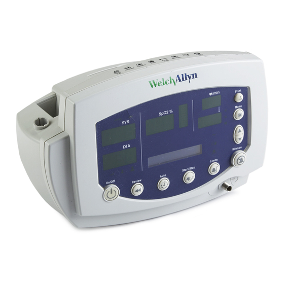
- Page 9 Safety Summary Symbols The monitor front panel controls are described in more detail throughout this document. Front Panel Controls Set alarm limits Power on/off Silence alarms Print patient data Scroll up/down Review patient data Scroll forward/back Increase/decrease value (The scroll icon appears as these two arrows in the documentation.) Set an NIBP automatic Start/stop an NIBP cycle...
- Page 10 Symbols Safety Summary Front Panel Displays and Indicators Systolic pressure Temperature Diastolic pressure Arterial hemoglobin oxygen saturation Pulse rate pulse Pulse strength amplitude indicator message MAP (mean arterial pressure) Neonatal window ° ° C Degrees Celsius Pediatric ° ° F Degrees Fahrenheit Adult Monitored temperature...
-
Page 11: Overview
This guide applies only to the Vital Signs Model 300 Series. For servicing the previous (52000- series) version of the Vital Signs Monitor, refer to Welch Allyn service manual 95P445E, which is available on the TechView CD (900298-1). -
Page 12: Returning Products
• Include a packing list. • Write the Welch Allyn RMA number with the Welch Allyn address on the outside of the shipping carton. United States federal regulations require that any unit received by Factory Service must be free from blood-borne pathogens before processing. -
Page 13: Product Configurations
Overview Product Configurations Product Configurations Model numbers for the configurations are as follows: Model Monitoring Parameters Serial Number Number Prefix 53000 NIBP 5300P NIBP, Printer 530T0 NIBP, Temperature 530TP NIBP, Temperature, Printer 53N00 NIBP, SpO 53N0P NIBP, SpO , Printer 53NT0 NIBP, SpO , Temperature... -
Page 14: Service Options
All repairs on products under warranty must be performed or approved by Welch Allyn. Refer all warranty service to Welch Allyn Factory Service or another authorized Welch Allyn Service Center. Obtain an RMA number for all returns to Welch Allyn Factory Service – see Returning Products (page 12) Caution Unauthorized repairs will void the product warranty. -
Page 15: Service Menu
Overview Service Menu Service Menu To see the service menu, first power the monitor off. Press and hold for 3 seconds. While is depressed, press . The monitor displays the message Service Mode, runs a self-test, and then displays the main software version number (M: 1.00.00). Press repeatedly to cycle to the menu selection of interest. - Page 16 Service Menu Overview Service Manual Vital Signs Monitor Series 300...
-
Page 17: Functional Verification
3 - Functional Verification Functional Verification Overview This section describes the procedure for a complete functional test to support recommended preventive-maintenance schedules. The verification includes tests for a monitor configured with the printer, temperature, and options. Perform only the tests applicable to the actual configuration. A checklist of the functional tests is provided on page 35. -
Page 18: Equipment Required
(Use the female end from the cable set) Welch Allyn Monitor Service Utility 840-0676-XX (required for NIBP repair or replacement; not required for functional testing) Service Serial Cable (for use with the Welch Allyn 008-0842-XX Monitor Service Utility 840-0676-XX) NIBP tubing connector, threaded 600-0021-XX tubing, 1’... -
Page 19: Functional Verification Procedure
• If the monitor is configured with the temperature option, connect the temperature probe and insert it into the probe well. • If you are using the optional Welch Allyn Model 9600 Calibration Tester (01800-200), plug it in and set it to 96.4° F (35.8° C). - Page 20 Functional Verification Procedure Functional Verification Monitor-Off Current With the monitor powered down, verify that the current draw from the power supply is less than 1 mA. Power-On Self-Test 1. Power the monitor on. If the monitor displays error E38, power the monitor off and then power it on again.
- Page 21 Functional Verification Functional Verification Procedure Baseline Current Draw 1. With the monitor powered on, wait for the monitor LEDs to blank. In this state, the SpO2 % reads - -, the time of day is displayed in the message window, and the rest of the displays are blank.
-
Page 22: Nibp
Functional Verification Procedure Functional Verification NIBP Characterization Test 1. Attach a neonate hose (part 008-0265-01) to the NIBP fitting on the monitor. 2. Prepare the 60-mL syringe as follows, with reference to the illustration below: a. Move the syringe plunger to the 35 mL line. b. - Page 23 NIBP module is not properly characterized, the monitor could overinflate a neonatal cuff, which could create a hazard for neonatal patients. If you cannot characterize the NIBP module, remove the monitor from service immediately and return it to Welch Allyn for service. (See Returning Products page 12.)
- Page 24 Functional Verification Procedure Functional Verification 5. Wait another 10 seconds, note the current pressure, and verify that it has not dropped more than 8 mmHg (1.1 kPa) below the pressure noted in step 6. Press several times to select 0 mmHg (0 kPa). The valve opens to release pressure. 7.
-
Page 25: Inflation
Functional Verification Functional Verification Procedure Valve/Pump Current 1. Press to select 0 mmHg (0 kPa) target pressure. 2. While watching the current meter, press to select 80 mmHg (10.7 kPa) target pressure. 3. Note the highest current reading during inflation. 4. -
Page 26: Printer
Functional Verification Procedure Functional Verification Printer 1. Put the monitor into Service Mode. 2. Verify that the printer has paper. 3. Press . Verify that a settings report prints, and that it contains no printed anomalies and no missing or faded sections. With a new roll of paper, the first line might be faded. - Page 27 Functional Verification Functional Verification Procedure Welch Allyn Vital Signs Monitor -- Unit Settings -- 13:04:21 15-Oct-2003 Calibration Record ------------------ Serial #: XXXXX.XXXX Serial # signature: NULL Calibration time/date 12:00:00 01-Jan-2000 Calibration signature NULL Language: 0) English Configuration SpO2 Temp = Printer = Ambient bias X.XX...
-
Page 28: Spo
Functional Verification Procedure Functional Verification Perform one of the following two SpO tests. Testing the Monitor Only Use this procedure to test only the monitor SpO function. 1. Power the monitor off. 2. Connect the Nellcor SRC-MAX SpO functional tester to the SpO input connector through a Nellcor DEC-8 extension cable. - Page 29 Functional Verification Functional Verification Procedure % SpO Rate 60 (Motion Artifact not selected) 2. Connect an SpO sensor to the simulator optical finger and to the monitor. 3. Wait for the monitor display to stabilize. 4. Verify an SpO saturation level of 94 ± 4. 5.
-
Page 30: Temperature
Testing the Probe with the Monitor Use this procedure to test the temperature function while verifying the temperature probe. 1. If the Welch Allyn 9600 Calibration Tester (01800-200) is not already warmed up, warm it up as follows: a. Set the 9600 Calibration Tester temperature switch to 96.4 °F (35.8 °C). -
Page 31: Nurse Call
Functional Verification Functional Verification Procedure Nurse Call Relay Verification With reference to the drawing and table below, use an ohmmeter to check the contact resistance at the output pins of the Nurse Call connector, while the monitor is in the alarm state and while the monitor is out of the alarm state. -
Page 32: Battery
The patient isolation test requires an AC Withstand Voltage (hi-pot) Tester, such as the AR 3605 or equivalent. If this equipment is not available, Welch Allyn can perform the patient isolation test for you quickly, for a nominal fee. - Page 33 Functional Verification Functional Verification Procedure Warning The patient isolation test involves exposure to extremely high voltages, and is therefore extremely hazardous. Always follow the tester manufacturer’s operation instructions exactly. Failure to perform this test properly can result in serious injury or death. This test must be performed by qualified service personnel only.
- Page 34 All wires connected High Voltage cable Connector together and terminated appropriately for your hi-pot tester Nurse Call Welch Allyn Nurse Call Nurse Call Connector All wires connected High Voltage cable 008-0634-XX together and terminated (Uses Lemo connector appropriately for your PAB.MO.4GLAC397.)
-
Page 35: Checklist And Test Results Report Form
Functional Verification Checklist and Test Results Report Form Checklist and Test Results Report Form Use a copy of this form to track your progress through the validation tests. Pass Fail N/A) Test Result Battery Charging Power-on Self-test Beeper Monitor Off Current (mA): Init/Idle Current (mA):... - Page 36 Checklist and Test Results Report Form Functional Verification Here is an example of verification results for a typical monitor. Pass Fail N/A) Test Result Battery Charging charge symbol lit Power-on Self-test normal Beeper audible Monitor Off Current (mA): 0.00 Init/Idle Current (mA): 0.467 mA Baseline Current (mA): 0.199 mA...
-
Page 37: Troubleshooting And Repair
Directions for Use for information on the cause and suggested remedy for those errors. Caution Replace parts, components, or accessories only with parts supplied or approved by Welch Allyn. The use of any other parts can lead to inferior monitor performance and will void the product warranty. Symptom... - Page 38 Troubleshooting Chart Troubleshooting and Repair Symptom Possible Cause Suggested Action Error code E31 RAM test failure. Cycle the power. If the error persists, return the monitor to an authorized service center for replacement of the main board. Error code E32 Factory data failure.
-
Page 39: Requirements For Module-Level Repair And Replacement
If the NIBP module is not properly characterized, the NIBP cuff could overinflate, which could be hazardous to neonatal patients. The Welch Allyn Monitor Service Utility facilitates this characterization procedure. See page 40 for more information. -
Page 40: Welch Allyn Monitor Service Utility
008-0842-XX or equivalent. Monitor Software Utility Installation To install the Welch Allyn Monitor Service Utility on a PC, insert the CD into the CD drive. • If Autostart is enabled on the PC, the installation program starts automatically. • If Autostart is not enabled on the PC, manually start the installation program as follows: Start >... -
Page 41: Characterizing Nibp
Troubleshooting and Repair Welch Allyn Monitor Service Utility Characterizing NIBP To characterize the NIBP module, start the Welch Allyn Monitor Service Utility and click on Characterize NIBP. Click Help in the utility menu, and perform the procedure as indicated. Warning If you cannot characterize the NIBP module, return the monitor to Welch Allyn for service. - Page 42 Welch Allyn Monitor Service Utility Troubleshooting and Repair Service Manual Vital Signs Monitor Series 300...
-
Page 43: Disassembly Procedure
5 - Disassembly Procedure Procedures Overview These procedures cover monitor disassembly and board removal. Unless otherwise noted, the assembly procedure is simply the reverse of the disassembly procedure. Caution Perform all repair procedures at a static-protected station. Observe recommended screw torque specifications, especially with screws that secure directly into plastic standoffs. -
Page 44: Connectors
Procedures Overview Disassembly Procedure Connectors Caution All connectors are keyed or coded to facilitate proper connection. Take care to correctly align all connector halves before attempting to connect them. Connector Types The procedures described below require you to disconnect and reconnect ZIF (zero-insertion force) connectors, squeeze-release connectors, and pressure connectors. - Page 45 Disassembly Procedure Procedures Overview Main Board Connectors For the best results when disconnecting cables from the main board, disconnect the upper cables first and work your way to the bottom of the board, in approximately the following order: Main-board Connector Connects With (Refer to the drawing of the main board, on...
-
Page 46: Remove And Disconnect The Battery
Remove and Disconnect the Battery Disassembly Procedure Board Connectors Connector Connects With Connector Connects With side panel Main board – J7 NIBP Board Connectors Connector Connects With Connector Connects With Main board – J7 Pump Temperature Board Connectors Connector Connects With Connector Connects With Main board –... -
Page 47: Separate The Front And Rear Chassis
Disassembly Procedure Separate the Front and Rear Chassis 3. Slide the battery out of the battery compartment. This might require lightly shaking the monitor. 4. Disconnect the battery from the monitor. Separate the Front and Rear Chassis 1. Remove the three screws securing the rear chassis. Vital Signs Monitor Series 300 Service Manual... - Page 48 Separate the Front and Rear Chassis Disassembly Procedure Housing Screws 2. Place the unit upright, with the front of the unit facing you. 3. Tilt the top of the front chassis away from the rear chassis while lifting the front chassis, freeing the front chassis from the corner tab feature on the bottom left-hand corner of the rear chassis.
- Page 49 Disassembly Procedure Separate the Front and Rear Chassis 4. Disconnect the NIBP hose from the connector on the front chassis. Disconnect the NIBP hose from the front chassis 5. Disconnect the display-board flex cable (J5) from the main board. Disconnect the display-board flex cable from the main board (J5).
-
Page 50: Disassemble The Front Chassis Assembly
Disassemble the Front Chassis Assembly Disassembly Procedure Temperature-board flex cable (to J12 on the main board) Ferrite bead on the rear chassis Ferrite bead on the rear chassis Display-board flex cable (to J5 on the main board) Disassemble the Front Chassis Assembly The front chassis assembly contains the display board, keypad, and NIBP air fitting. - Page 51 Disassembly Procedure Disassemble the Front Chassis Assembly 5 screws securing the LED display board 2. Lift out the display board. 3. Remove the keypad. Vital Signs Monitor Series 300 Service Manual...
- Page 52 Disassemble the Front Chassis Assembly Disassembly Procedure Printer button Reassembly Notes If you are replacing the keypad and your monitor does not include the thermal printer option, the Printer button must be removed from the keypad before you reinstall the keypad.
-
Page 53: Remove The Lcd Display From The Main Board
Disassembly Procedure Remove the LCD Display from the Main Board Remove the LCD Display from the Main Board Disconnect the LCD display module from connector J5 on the main board Remove the Main Board from the Rear Chassis Assembly 1. Disconnect the temperature module flex cable from J12 on the main board. Temperature module flex cable Main board J12... - Page 54 Remove the Main Board from the Rear Chassis Assembly Disassembly Procedure Unlatch the ZIF connector before removing or inserting the flex cable Service Manual Vital Signs Monitor Series 300...
- Page 55 Disassembly Procedure Remove the Main Board from the Rear Chassis Assembly 2. Remove the four screws securing the main board to the rear chassis. 4 screws securing the main board 3. Pull the lower right-hand corner of the main board away from the rear chassis, just far enough to free the RS232 connector housing on the main board from the RS232 connector slot on the rear chassis.
- Page 56 Remove the Main Board from the Rear Chassis Assembly Disassembly Procedure 4. Carefully tip the upper edge of the main board away from the rear chassis, far enough to access the uppermost connectors on the component side of the board. 5.
- Page 57 Disassembly Procedure Remove the Main Board from the Rear Chassis Assembly (on the back side of the board) (on the back side of the board) Main Board Reassembly Notes Caution Take care when reconnecting the main board power connector (J3). If the cable connector is connected improperly, the monitor could be damaged when power is applied.
-
Page 58: Disassemble And Remove The Nibp Assembly
Disassemble and Remove the NIBP Assembly Repair or replacement of the NIBP assembly is not supported. All NIBP service must be performed at an authorized Welch Allyn service center. 1. Remove the tubing and the pump. Service Manual... - Page 59 Disassembly Procedure Disassemble and Remove the NIBP Assembly a. Disconnect the tubing from the manifold on the NIBP board. b. Disconnect the two sections of tubing from the pump. NIBP tubing connection points on the pump NIBP tubing connection points on the manifold c.
- Page 60 Disassemble and Remove the NIBP Assembly Disassembly Procedure 4 screws securing the NIBP board b. Remove the NIBP board. NIBP Reassembly Notes Warning You must characterize the NIPB module whenever you replace any NIBP component (pump, tubing, air filter, check valve, or NIBP module). If the NIBP module is not properly characterized, the pump could overinflate a neonatal cuff, which could be hazardous to neonatal patients.
-
Page 61: Remove And Disassemble The Printer Assembly
Disassembly Procedure Remove and Disassemble the Printer Assembly Check valve Air filter Remove and Disassemble the Printer Assembly 1. Remove the printer door. a. Open the printer door and remove the roll of printer paper. b. Push the printer door toward the rear of the monitor until it snaps out of the two support spindles on the printer frame. - Page 62 Remove and Disassemble the Printer Assembly Disassembly Procedure Spindles 2. Remove the printer assembly. Push the plastic legs of the printer assembly outward and pull the printer assembly forward to free it from the snap-in seating of the rear chassis bulkhead. Service Manual Vital Signs Monitor Series 300...
- Page 63 Disassembly Procedure Remove and Disassemble the Printer Assembly Push the printer legs very slightly outward while pulling them toward you. Vital Signs Monitor Series 300 Service Manual...
- Page 64 Remove and Disassemble the Printer Assembly Disassembly Procedure 3. Remove the printer mechanism and the printer board. a. Turn the printer assembly upside-down, and release the ZIF connector latches (CN2) on the printer board. Printer flex cable ZIF connector latches b.
- Page 65 Disassembly Procedure Remove and Disassemble the Printer Assembly d. Remove the screw securing the printer board to the printer assembly. One screw securing the printer board Vital Signs Monitor Series 300 Service Manual...
- Page 66 Remove and Disassemble the Printer Assembly Disassembly Procedure e. If you are replacing the printer board, remove the cables from connectors CN1 and CN3 for use on the replacement board. Printer Reassembly Notes a. When connecting the printer assembly board to the plastic printer housing, be sure the printer board is seated flat on the housing, within the guide rails on either side of the housing, and with the front of the board secured under the tab on the front of the housing.
- Page 67 Disassembly Procedure Remove and Disassemble the Printer Assembly printer-frame “piano” legs are toward the front, extending downward from the assembly. c. Partially insert the printer frame assembly into the printer well in the rear chassis, aligning the rear side rails for insertion between the two slotted side latches on the top of the printer well of the rear chassis.
-
Page 68: Disassemble The Temperature Module
Disassemble the Temperature Module Disassembly Procedure Disassemble the Temperature Module Disassembly of the temperature module does NOT require removal of the main board. 1. Remove the temperature module from the monitor. a. Remove the two screws (located on the left side, inside the rear chassis) securing the module to the slots on the left side of the rear chassis. - Page 69 Disassembly Procedure Disassemble the Temperature Module 2. Remove the temperature-board assembly from the SureTemp Plus module as follows: a. Remove the four screws securing the inside panel to the module housing. 4 screws securing the inside panel to the module housing b.
- Page 70 Disassemble the Temperature Module Disassembly Procedure 4 screws securing the temperature board to the module housing c. Tilt the temperature board and rotate it clockwise to free the cable connector from the connector slot (J5) in the housing; then lift the board out of the housing. Temperature cable connector slot Temperature cable connector d.
-
Page 71: Disassemble The Spo
Disassembly Procedure Disassemble the SpO Assembly 3 screws securing the temperature probe-well housing Temperature ZIF connector cable Temperature probe-well housing Temperature Module Reassembly Notes To install the temperature board in the module housing: 1. Square the circuit board in the housing to fit the probe-well receiver into the top of the outside housing. - Page 72 Disassemble the SpO Assembly Disassembly Procedure 4 screws securing the assembly to the rear chassis b. Remove the side panel and board assembly form the rear chassis. 2. Remove the SpO board. a. Remove the two screws securing the board to the side panel. Service Manual Vital Signs Monitor Series 300...
- Page 73 Disassembly Procedure Disassemble the SpO Assembly 2 screws securing the SpO board to the SpO assembly b. Disconnect J1 and J2. Caution To avoid stressing and damaging the J1 flex cable, disconnect the cable by gripping the J1 flex-cable connector with pliers and separating the connector halves without stressing or otherwise putting any pressure on the flex cable itself.
- Page 74 Disassemble the SpO Assembly Disassembly Procedure Grip with pliers here, and separate the J1 connector halves. Never pull directly on the cable itself. Service Manual Vital Signs Monitor Series 300...
- Page 75 Disassembly Procedure Disassemble the SpO Assembly Reassembly Notes The J2 connector halves are keyed to prevent incorrect connection. However, to facilitate the connection, align the red line on the edge of the ribbon cable with pin 1 of the connector on the SpO board.
- Page 76 Disassemble the SpO Assembly Disassembly Procedure Service Manual Vital Signs Monitor Series 300...
-
Page 77: Replacement Parts
This list includes field-replaceable service parts only. Product accessories, including patient sensors, probes, cables, batteries, probe covers, printer paper and other consumable items, are listed separately in the Welch Allyn Products and Accessories Guide (810-0409-00), which is available from Welch Allyn Customer Service. - Page 78 Replacement Parts Option 010-0232-XX Side-panel Assembly, SpO , MP-506 031-0139-XX Board, SpO , Nellcor MP-506 660-0233-XX Cable Assembly, SpO Main Interface Temperature Option 21327-000 PCB, Temperature Module 630-0211-XX Outside Housing, Temperature Module 630-0238-XX Inside Panel, Temperature Module 660-0230-XX Cable, Flex, Temperature Main Board Printer Option 532012-000 PCB, Printer...
Need help?
Do you have a question about the 53 and is the answer not in the manual?
Questions and answers
How do I get a replacement battery for my Welch Allyn dinamap?
The replacement battery for the Welch Allyn Dinamap Model 53 is listed as part number 407560 under "Battery assembly." To obtain a replacement, you should order this part number from an authorized Welch Allyn supplier or service center.
This answer is automatically generated