
Subscribe to Our Youtube Channel
Related Manuals for FLIR Photon Block 2


Summary of Contents for FLIR Photon Block 2
-
Page 1: User Guide
Photon Block 2 User Guide 412-0035-00-10 Version 100 FLIR Systems Indigo Operations 70 Castilian Dr. Goleta, CA 93117-3027 805 964-9797 FAX 805 685-2711 www.indigosystems.com... -
Page 2: Table Of Contents
PHOTON DIGITAL DATA CHANNEL................29 ..................29 SING THE IGITAL HANNEL PHOTON PHYSICAL INTERFACE ................30 ......................30 IMENSIONED RAWINGS ............................. 30 EIGHT ..........................31 OUNTING APPENDIX A: PIN-OUT DEFINITIONS ................37 I/O M ..........................37 ODULE COPYRIGHT NOTICE © FLIR SYSTEMS CORPORATION 2006... -
Page 3: Photon User Guide 412-0035-00-10 Version
Photon User Guide 412-0035-00-10 Version 100 Cautions: • Do not remove the camera cover. Disassembly of the camera (including removal of the cover) can cause permanent damage and will void the warranty. • Operating the camera outside of the specified input voltage range or the specified operating temperature range can cause permanent damage. -
Page 4: Introduction
Photon User Guide 412-0035-00-10 Version 100 1 INTRODUCTION The Photon is a long-wavelength (7.5 – 13.5 microns) uncooled microbolometer camera designed for infrared imaging applications that demand absolute minimum size, weight, and power consumption. It is available with five different lens options: 14.25 mm focal length (50° H field of view or FOV), 19 mm focal length (36°... -
Page 5: Unpacking Your Photon Camera
3 UNPACKING YOUR PHOTON CAMERA The items shown in Figure 2 come standard in your Photon Camera package. If there is any discrepancy between this list and the contents of your camera package, please contact FLIR Systems Customer Support immediately at (805) 964-9797. -
Page 6: Optional Photon Accessories
Photon User Guide 412-0035-00-10 Version 100 4 OPTIONAL PHOTON ACCESSORIES • Digital data serial-to-parallel module (parallel data cable sold separate) • Pleora IPort • Battery Pack Figure 3: Some of the Photon Accessories 5 OVERVIEW OF THE PHOTON ELECTRICAL INTERFACE Depending on connector type, either a 15-pin HD D-Sub or a 30-pin SAMTEC, thru which input/output signals are available on the back of the Photon camera. - Page 7 Photon User Guide 412-0035-00-10 Version 100 The Photon camera provides all input/output signals via a single 30-pin SAMTEC TFML-115- 02-S-D-P connector (J1) with pin definitions as shown in Table 2 The signals on this connector include input power, analog video output, serial communication channel for command and control, external sync, voltage output, I/O pins and the digital data output.
-
Page 8: Input Power
Photon User Guide 412-0035-00-10 Version 100 Input Power Included with the Photon camera is an AC/DC converter that generates 8VDC input power from 110 VAC or 220 VAC. If you prefer to provide your own power supply, please verify that the input power at the camera connector meets the specifications shown in Table 3 when applied across PWR_IN and GND pins. -
Page 9: Command And Control Channel
Photon User Guide 412-0035-00-10 Version 100 Command and Control Channel Remote control of the Photon camera is provided via a RS-232 serial interface consisting of signals named RX, TX and GND using 3.3 volt signal levels. Section 7 provides information regarding remote control using the Photon OEM GUI. -
Page 10: Voltage Outputs
1.50V + 0.05mV Max. Supply 500 mA 700 mA Current Input/Output Pins The Photon camera allows for custom defined I/O pins that can be programmed at the factory for selected applications. Contact FLIR Systems Customer Support at (805) 964-9797 for details. -
Page 11: Basic Operation Of The Photon Camera
Photon User Guide 412-0035-00-10 Version 100 6 BASIC OPERATION OF THE PHOTON CAMERA Note: If you are using the Ethernet Module or SIPO adapter additional instructions may also be provided. 1. Remove the lens cap. (Remember to replace the lens cap when the camera is not in use to prevent accidental scratching and dust contamination.) 2. -
Page 12: Remote Control Of The Photon Camera
Photon User Guide 412-0035-00-10 Version 100 To video monitor To electrical outlet To PC (only required if using RS-232 interface.) Figure 6: Photon after cabling 7 REMOTE CONTROL OF THE PHOTON CAMERA The Photon provides advanced camera control through an RS-232 serial interface. This can be accessed using a PC with the standard serial communications port and the I/O Module. -
Page 13: Installation Of Photon Control Panel Software
Photon User Guide 412-0035-00-10 Version 100 Installation of Photon Control Panel Software 1. Insert the CD marked Photon OEM GUI into your CD-ROM drive. If the setup program (setup.exe) does not execute automatically, then execute it by finding setup.exe in the CD-ROM with Windows Explorer and double-clicking the icon. -
Page 14: Operation Of The Photon Control Panel
Photon User Guide 412-0035-00-10 Version 100 Operation of the Photon Control Panel When the Control Panel successfully links to the camera, you may see the communications window shown in Figure 7 then select the correct comm. Port and hit apply. The Control Panel provides five tabs allowing for camera control as well as the ability to save/load configuration settings and custom splash screens. -
Page 15: Control Panel Camera Tab
Photon User Guide 412-0035-00-10 Version 100 7.1.1 Control Panel Camera Tab The Camera Tab on the Control Panel, shown in Figure 8, provides the ability to modify the Flat Field mode, the Digital Output mode as well as select the Dynamic Range and External Sync modes. - Page 16 Photon User Guide 412-0035-00-10 Version 100 1. Automatic. In the Automatic FFC mode, the camera performs FFC whenever its temperature changes by a specified amount or at the end of a specified period of time (whichever comes first). When this mode is selected, input windows are available on the Control Panel for specifying the temperature change and the number of frames that trigger automatic FFC.
- Page 17 Photon User Guide 412-0035-00-10 Version 100 1. Off. The digital data stream coming from the Photon camera is turned off. 2. 8-bit data. Data from the 320x240 (NTSC) or 320x255 video pixels (PAL) is provided after application of the current AGC or Image-Optimization mode (refer to Section 7.1.2), isotherms, and on-screen symbols.
- Page 18 Photon User Guide 412-0035-00-10 Version 100 1. Disabled Mode: The camera will turn off frame synchronization. 2. Slave Mode: The camera will accept a frame synchronization signal on the interface connector. 3. Master Mode: The camera will output a frame synchronization signal on the interface connector when configured as a master.
-
Page 19: Control Panel Video Tab
Photon User Guide 412-0035-00-10 Version 100 7.1.2 Control Panel Video Tab The Video Tab on the Control Panel, shown in Figure 10, provides the ability to modify six different Photon modes: Image Orientation mode, Pan & Zoom, Polarity/LUT, Dynamic Detail Enhancement, Video Standard mode and Test-Pattern mode. - Page 20 Photon User Guide 412-0035-00-10 Version 100 Pan & Zoom: The Pan & Zoom also called PAN_AND_TILT command controls the camera when the image is zoomed. It does not have any effect when the image is not zoomed. The center of the screen is considered as coordinate (0,0). A positive number is needed to pan right and negative number to pan left.
- Page 21 Photon User Guide 412-0035-00-10 Version 100 VIDEO Figure 12: Maximum ROI If the ROI is set to the size of the visible portion of the zoomed image as shown in Figure 13 and the image is tilted to the maximum limits as shown in Figure 14, pixels will not be dropped from the ROI but the AGC will change as the ROI changes with the pan and tilt coordinates.
- Page 22 Photon User Guide 412-0035-00-10 Version 100 Figure 15: ROI larger than Zoomed video Figure 16: ROI clipped Note: Selecting the Pan & Zoom mode will not affect the digital data output. Polarity/LUT: Imagery can be displayed in a variety of LUTs or Look Up Tables. The most common selection is either white-hot (hotter objects brighter than cooler objects) or black- hot polarity (hotter objects darker than cooler objects).
- Page 23 Photon User Guide 412-0035-00-10 Version 100 Dynamic Detail Enhancement or DDE filter: This option applies a Bi-Lateral filter to enhance image. The commands to control the DDE settings are Filter Gain to control the gain, Filter Control to control the DDE filter threshold and Spatial Control to control the spatial threshold of the DDE filter.
- Page 24 Photon User Guide 412-0035-00-10 Version 100 Test-Pattern Mode: A Test-Pattern mode is provided to verify camera electronics. 1. Off. No test-pattern is provided in this mode. This is the normal mode for viewing thermal imagery. 2. Ramp. In this ramp mode, the test pattern shown in Figure 17 is provided at the analog and digital data channels.
-
Page 25: Control Panel Agc Tab
Photon User Guide 412-0035-00-10 Version 100 7.1.3 Control Panel AGC Tab The AGC Tab on the Control Panel, shown in Figure 18, provides the ability to modify three different camera modes: AGC or Automatic Gain Control mode, AGC Parameters, Linear Parameters and Region Of Interest or ROI. - Page 26 Photon User Guide 412-0035-00-10 Version 100 2. Auto-Bright. In Auto-Bright mode, image brightness is optimized automatically as the scene varies but contrast is manually specified. Generally, Automatic AGC produces a better image than Auto-Bright, but in some cases, specifying contrast manually can improve the display of a specific feature in a scene.
- Page 27 Photon User Guide 412-0035-00-10 Version 100 Note: In Manual mode and Once Bright mode, the brightness setting must be updated as the camera temperature changes. To avoid this issue, it is recommended to use Automatic or Auto- Bright modes when possible. Also, only in the 8-bit mode will selecting AGC mode affect the digital data output.
-
Page 28: Control Panel About Tab
Timeout”, the link between the camera and Control Panel has been disrupted. Verify that the camera is still powered and that the serial cable to the PC has not been disconnected. If you cannot re-establish the Control Panel link, call FLIR Customer Support at (805) 964-9797 for assistance. -
Page 29: Photon Digital Data Channel
– a clock, a composite sync (frame sync and line sync), and serial data. A serial-in-parallel-out (SIPO) module is available from FLIR Systems for converting the serial data to 14-bit parallel LVDS output (plus frame sync, line sync, and pixel clock). The parallel data can be captured using a frame-grabber board installed in a PC. -
Page 30: Photon Physical Interface
Photon User Guide 412-0035-00-10 Version 100 follow the instructions with the device. If you are using custom cabling and/or interface electronics, contact FLIR Systems Customer Support at (805) 964-9797 if you need additional assistance. 1. Follow the steps shown in Section 6 for basic operation of the Photon camera. After verifying that the camera is operating properly, disconnect power from the Interface Module. -
Page 31: Mounting
Photon User Guide 412-0035-00-10 Version 100 Table 10: Photon Camera Core and Lens Combined Weight Photon camera focal Weight length 14.25 mm 19 mm 30 mm 35 mm 50 mm Mounting There is a single threaded mounting hole on the bottom surface of the camera. For precision alignment, there is also a hole on the bottom surface that allows an anti-clocking pin to be installed in the mounting platform. - Page 32 Photon User Guide 412-0035-00-10 Version 100 Figure 21: Photon 14-mm lens configuration...
- Page 33 Photon User Guide 412-0035-00-10 Version 100 Figure 22: Photon 19-mm lens configuration...
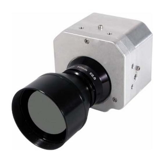
- Page 34 Photon User Guide 412-0035-00-10 Version 100 Figure 23: Photon 30-mm lens configuration...
- Page 35 Photon User Guide 412-0035-00-10 Version 100 Figure 24: Photon 35-mm lens configuration...
- Page 36 Photon User Guide 412-0035-00-10 Version 100 Figure 25: Photon 50-mm lens configuration...
-
Page 37: Appendix A: Pin-Out Definitions
Photon User Guide 412-0035-00-10 Version 100 APPENDIX A: PIN-OUT DEFINITIONS I/O Module Camera Connector: Same as camera connector. See Table 1for valid mates. Power Connector: Mates to Switchcraft S760 Miniature Power Plug. Video Connector: Mates to 75Ω BNC twist-on plug. Serial Connector: Mates to DB9 Male. - Page 38 Photon User Guide 412-0035-00-10 Version 100 Table A4: I/O Module Digital Data Connector Pin-Out Pin # Signal Name Signal Definition DATA_SYNC Digital data sync (LVDS high) DATA_OUT+ Digital data output channel (LVDS high) DATA_CLK+ Digital output channel clock (LVDS high) DATA_SYNC- Digital data sync (LVDS low) DATA_OUT-...
Need help?
Do you have a question about the Photon Block 2 and is the answer not in the manual?
Questions and answers