Table of Contents
Advertisement
PHONE:
INTL:
Document Number: TAU-0035-00-10
Version: 100
Issue Date: April 2009
This document is controlled to FLIR Technology Level EAR 1. The information contained in this document is proprietary and/or restricted and pertains
to a dual use product controlled for export by the Export Administration Regulations (EAR). This document and data disclosed herein or herewith is
not to be reproduced, used, or disclosed in whole or in part to anyone without the written permission of FLIR Systems, Inc. Diversion contrary to US
law is prohibited. US Department of Commerce authorization is not required prior to export or transfer to foreign persons, parties, or uses otherwise
prohibited.
User's Manual
1-888-919-2263
FAX:
+1-845-343-4077
EMAIL:
+1-845-343-4299
support@oemcameras.com
Tau
TM
Advertisement
Table of Contents

Subscribe to Our Youtube Channel
Related Manuals for FLIR TAU


Summary of Contents for FLIR TAU
- Page 1 Export Administration Regulations (EAR). This document and data disclosed herein or herewith is not to be reproduced, used, or disclosed in whole or in part to anyone without the written permission of FLIR Systems, Inc. Diversion contrary to US law is prohibited.
- Page 2 EMAIL: support@oemcameras.com © FLIR Inc., 2009. All rights reserved worldwide. No parts of this manual, in whole or in part, may be copied, photocopied, translated, or transmitted to any electronic medium or machine readable form without the prior written permission of FLIR Inc.
-
Page 3: Table Of Contents
2.3 Software accessory SDK for Windows & Embedded ......... 2-3 3 Basic Operation of the Tau and GUI 3.1 Operation of the Tau camera using the Photon development kit ....3-1 3.2 Remote control of the Tau camera ............3-2 3.3 Connecting the serial communications interface using the development kit .. - Page 4 B.8 Analog Video Interface ..............B-12 B.9 Digital Data Channels ................ B-13 Appendix C Mechanical IDD Reference Tau Camera Core Interface Description Document 5mm - 19mm, ....C-3 Tau Camera Core Interface Description Document 25mm......C-4 Tau Camera Core Interface Description Document 35mm......C-5 Tau Camera Core Interface Description Document 60mm......C-6...
-
Page 5: Introduction
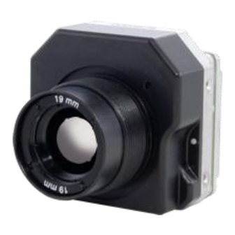
Introduction The Tau is a long-wavelength (8 – 14 microns) uncooled microbolometer camera designed for infrared imaging applications that demand absolute minimum size, weight, and power consumption. It is available with multiple different lens focal length options, as well as a No Lens option intended for customers who mount their own lens and perform ancillary Alternate Lens Calibration—See “Software accessory SDK for Windows &... -
Page 6: Tau Specifications
The Tau camera is an export controlled item. In order to increase the Camera’s exportability, a ‘Slow Video’ version of Tau is available. The frame rate is reduced to approximately 9 Hz. This change allows Tau to be exported without US export license to most countries. -
Page 7: Available Tau Configurations
Tau User’s Manual 1—Introduction Available Tau Configurations The Tau is available with different lenses providing different fields of view and the ‘Slow Video’ or ‘9 Hz’ option for license-free exportability. Note Contact FLIR CVS Customer Support or your local FLIR sales representative for information on available Tau camera configurations, part numbers, and ordering information. -
Page 8: Unpacking Your Tau Camera
Please unpack the camera heeding customary Electrostatic Sensitive Device (ESD) precautions including static safe work station and proper grounding. The Tau camera is packaged in foam to prevent damage during shipping. It is also placed in a conductive anti-static bag to protect from electrostatic discharge damage. -
Page 9: Optional Tau Accessories
Tau Video Power Com (VPC) Accessory The Tau VPC module is the first thing many users will connect their Tau camera, and for some customers it may be the only thing they will ever need. The VPC provides connection to a host computer for power, command/control, and digital image capture;... -
Page 10: Backward-Compatible Photon Accessories
Photon Replicator Board (26-pin to 50-pin adapter to Tau allowing use of existing Photon cables and accessories), and cables to facilitate AC power in and analog video out for your Tau camera. With this accessory kit, the customer only needs to purchase a standard RS-232 COM cable in order to perform advanced configuration using the free downloadable FLIR Camera Controller. -
Page 11: Software Accessory Sdk For Windows & Embedded
This accessory facilitates capture of the LVDS serial digital data channel from the Tau camera and mirrors it in a parallel format used with computer-based capture boards. - Page 12 2—Optional Tau Accessories Tau User’s Manual April 2009 TAU-0035-00-10, version 100...
-
Page 13: Basic Operation Of The Tau And Gui
The camera will take ~2 seconds to produce an image after you apply of power. You should see an initial splash screen with the FLIR logo displayed, and then live infrared long wave imaging video will follow! Point the camera in different directions and notice the imagery. If the video image appears low in contrast, point the camera at a scene with high thermal contrast such as at a person. -
Page 14: Remote Control Of The Tau Camera
Development Kit. This software provides remote control of various camera features and modes. The FLIR Camera Controller software is compatible with Windows XP . The PC must have a spare serial communications port or you must use the Tau VPC module USB accessory. Note A USB to Serial port adapter is acceptable, but the data communication rate must be set to 57600 BAUD. -
Page 15: Installing The Flir Camera Controller
Windows Uninstall utility via the Windows Control Panel before proceeding with this installation. This is an important step as camera malfunction is possible if you do not remove any older versions of Tau (or Omega/ Micron/A10) software. - Page 16 3—Basic Operation of the Tau and GUI Tau User’s Manual Step 9 Click Next>> at the Setup Welcome screen. When the installer finishes loading. Follow the prompts. Step 10 Select Destination Folder if different than the default. Then, click Install.
- Page 17 Tau User’s Manual 3—Basic Operation of the Tau and GUI Step 13 Installation is complete. You can start the application or create a shortcut to the application via the Start→ Programs→ Tau→ FLIR Camera Controller path. TAU-0035-00-10, version 100 April 2009...
-
Page 18: Connecting The Tau To A Pc Via The I/O Module
The FLIR Camera Controller remembers the last COM port that successfully communicated with a Tau camera and will use that port as the default at start of the application. If the connected camera is no longer on that port, the port setting pop-up window will appear asking for you to select the proper port setting. - Page 19 Tau User’s Manual 3—Basic Operation of the Tau and GUI Step 5 Connect to your camera by selecting Connect from the Camera menu. Step 6 If you want the FLIR Camera Controller to automatically connect when it is started, select Settings from the Tools menu, then check the Automatically connect on startup box in the Settings Framework tab.
-
Page 20: Troubleshooting The Flir Camera Controller
Verify that you selected the proper port if it was not detected automatically. Clicking in the lower right of the FLIR Camera Controller window on top of the word COM will bring up a dialog box indicating COM port. Also, try disconnecting and then re-connecting the RS-232 serial cable to the PC. -
Page 21: Operation Of The Flir Camera Controller
3—Basic Operation of the Tau and GUI Operation of the FLIR Camera Controller When the FLIR Camera Controller successfully links to the camera, you will see the window shown below. At the bottom of the application window, you should see Camera and FPA status. -
Page 22: Setup Tab
3—Basic Operation of the Tau and GUI Tau User’s Manual Setup Tab The Setup tab, shown below, provides the ability to do the following: • Modify the Flat Field Correction (FFC) • Set the External Sync mode • Freeze the video via the Operating Mode section •... - Page 23 (whichever comes first). When this mode is selected, input windows are available in the FLIR Camera Controller for specifying the temperature change and the number of frames that trigger automatic FFC. The temperature change is specified in degrees, with valid values in the range 0 to 100 in 0.1 degree increments.
- Page 24 Tau camera will remember these saved settings. If you do not click Save Settings, the changes you make via the FLIR Camera Controller will be valid only for the current session. Cycling power to the camera will revert to the previously saved settings.
- Page 25 = 16383 pix(25,409) = 0 Figure 3-5: Ramp test pattern example for Top Portion of Tau Ramp Image (Digital values shown apply to the optional 14-bit digital data stream.) The above ramp pattern repeats 19 times in the complete 320 x 256 image.
-
Page 26: Analog Video Tab
3—Basic Operation of the Tau and GUI Tau User’s Manual Analog Video Tab The Analog Video tab on the FLIR Camera Controller, shown below, provides the ability to modify four different Tau modes: • Image Orientation • Pan & Zoom •... - Page 27 Tau User’s Manual 3—Basic Operation of the Tau and GUI Image-Orientation Mode: Two Image-Orientation mode selections are provided. Select one or both to change the orientation of the video image. (Invert/Revert functions will be supported in July 2009.) Invert: The normal image is flipped vertically. The...
- Page 28 3—Basic Operation of the Tau and GUI Tau User’s Manual Polarity/LUT: The Tau camera detects and images the temperatures in a given scene. Within the camera, these temperatures are mapped (as determined by the AGC algorithm selected) to a range of 0 to 256 values.
- Page 29 Tau User’s Manual 3—Basic Operation of the Tau and GUI Flat-Field Correction (FFC): The Tau automatically performs flat-field corrections (see paragraph “Flat-Field-Correction Mode:” on page 3- 11). A green square is displayed on your video monitor as a warning that the FFC is going to take place. Use...
-
Page 30: 3.10 Digital Video Tab
Tau User’s Manual 3.10 Digital Video Tab Tau offers a LVDS interface digital output that can be configured in four modes. Changing these modes will have no effect on the analog (NTSC or PAL) signal. In order to access the digital output, you must use an advanced interface as described in Chapter 4, Tau Digital Data Channel. -
Page 31: 3.11 Agc Tab
Also, be aware that you can make AGC adjustments that will configure the Tau camera to produce no image (all black or all white). Restoring the Factory Defaults on the Setup Tab will return the camera to its factory default state and likely restore normal camera operation. - Page 32 3—Basic Operation of the Tau and GUI Tau User’s Manual AGC Modes: The Tau provides six AGC algorithms for Image-Optimization: Automatic: This is the most sophisticated algorithm and for most imaging situations, the best all-around choice. This factory default along with the default parameter settings should be used in general imaging situations.
- Page 33 Tau User’s Manual 3—Basic Operation of the Tau and GUI brightness) for the image. Upon entry into the linear histogram mode, the currently- stored values are applied (i.e. the power-on defaults or the last saved values). Logarithmic: The Logarithmic AGC algorithm operates identically to the Linear Histogram algorithm discussed above, except that the transfer function applied is logarithmic as opposed to linear.
-
Page 34: 3.12 Roi Tab
3.12 ROI Tab The Tau camera allows the user to set a Region of Interest (ROI) or a rectangle of pixels on the sensor array that the AGC algorithm will use for its calculations. The ROI can be set for either the entire frame size (0,0 : 320,256) or some smaller portion as shown below. -
Page 35: Tau Digital Data Channel
Tau Digital Data Channel Tau provides a digital data channel that outputs the camera’s data in a digital format. This channel can be used in conjunction with commercially-available digital frame grabbers, digital displays, or custom receive electronics. It can also be used with FLIR’s Ethernet Adapter. For Tau users with embedded or specialty applications that require custom control software, a Software Developer’s Kit (SDK) is available to support your development efforts. -
Page 36: Using The Digital Data Channel
Follow the steps in paragraph 3.1 “Operation of the Tau camera using the Photon development kit” on page 3-1 for basic operation of the Tau camera. After verifying that the camera is operating properly, disconnect power from the I/O Module. -
Page 37: Overview Of The Electrical Interface
Overview of the Electrical Interface Input Power The Tau camera operates from DC power per the specifications given below. It is common in simple operational scenarios to use an inexpensive wall-powered adapter. This type of adapter is what is included with the Accessory Kit. The connector pin-out tables indicate where power is to be applied (PWR_IN and GND pins). - Page 38 5—Overview of the Electrical Interface Tau User’s Manual Table 5-2 below identifies the function of each pin on the standard surface mount mating connector, Hirose DF12-50DS-0.5V(86). Table 5-2: 50-pin Hirose Connector Interface of the Camera Pin # Signal Name Signal Definition...
-
Page 39: Analog Video Output
If you are creating a custom cable to carry the analog video signal from the Tau camera to your monitoring or recording device, you should use 75 Ohm characteristic impedance coaxial cable and terminate into a 75 Ohm monitor. - Page 40 5—Overview of the Electrical Interface Tau User’s Manual April 2009 TAU-0035-00-10, version 100...
-
Page 41: Appendix A Pin-Out Definitions
Sleeve VIDEO_RTN analog video return Table A-3: I/O Module Serial Connector Pin-Out Pin # Signal Name Signal Definition RX_232 RS232 Receive channel TX_232 RS232 Transmit channel DGND Digital Ground 1,4, 6-9 Spare (do not connect) TAU-0035-00-10, version 100 April 2009... - Page 42 Appendix A—Pin-out Definitions Tau User’s Manual Table A-4: I/O Module Digital Data Connector Pin-Out Pin # Signal Name Signal Definition DATA_SYNC+ Digital data sync (LVDS high) DATA1_OUT+ Digital data 1 output channel (LVDS high) DATA2_OUT+ Digital data 2 output channel (LVDS high)
-
Page 43: Appendix B Serial Communication Technical Details
• For reference only, a sample command and response is shown in Table B-5. Table B-1: Serial Port Settings Parameter Value Baud rate: 57600 Data bits: Parity: None Stop bits: Flow control: None TAU-0035-00-10, version 100 April 2009... -
Page 44: Status Byte
Appendix B—Serial Communication Technical Details Tau User’s Manual Table B-2: Serial Packet Protocol Byte # Upper Byte Comments Set to 0x6E on all valid incoming messages Process Code Set to 0x6E on all outgoing replies Table B-3 Status Reserved Table B-4... -
Page 45: Function Byte
Tau User’s Manual Appendix B—Serial Communication Technical Details Function Byte • The list of valid commands that can be set in the Function Byte is shown in Table B- • For all reply messages, the camera will echo back the Function Byte of the previous incoming message. - Page 46 Appendix B—Serial Communication Technical Details Tau User’s Manual April 2009 TAU-0035-00-10, version 100...
- Page 47 Tau User’s Manual Appendix B—Serial Communication Technical Details TAU-0035-00-10, version 100 April 2009...
- Page 48 Appendix B—Serial Communication Technical Details Tau User’s Manual April 2009 TAU-0035-00-10, version 100...
- Page 49 Tau User’s Manual Appendix B—Serial Communication Technical Details TAU-0035-00-10, version 100 April 2009...
- Page 50 Appendix B—Serial Communication Technical Details Tau User’s Manual April 2009 TAU-0035-00-10, version 100...
- Page 51 Tau User’s Manual Appendix B—Serial Communication Technical Details TAU-0035-00-10, version 100 April 2009...
-
Page 52: Example Of The Format Of A Serial Message
Appendix B—Serial Communication Technical Details Tau User’s Manual B.4.1 Byte Count Bytes • On all incoming and outgoing messages, the Byte-Count Bytes are used to specify the total number of data bytes in the packet. (Note: the number of data bytes in the packet is not equal to the total number of bytes in the packet. -
Page 53: Description Of Serial Commands
Tau User’s Manual Appendix B—Serial Communication Technical Details Description of serial commands B.6.1 Camera Defaults The RESET_FACTORY_DEFAULTS command sets the current settings to the factory default values. In order to save these values as power up defaults, it is necessary to do a SET_DEFAULTS command. -
Page 54: Spare Serial Communications Channel
When the VIDEO_LO signal is tied to ground, the analog video signal meets the timing and voltage requirements of either NTSC or PAL protocol. (The FLIR Camera Controller software allows you to select between NTSC or PAL video output formats. The NTSC analog video format is the default in all cameras.) -
Page 55: Digital Data Channels
Tau User’s Manual Appendix B—Serial Communication Technical Details Digital Data Channels The camera provides two digital ports. • Port 1 consists of the signals SD_CLK+, SD_FSYNC+, and SD_DATA+. • Port 2 consists of the signal LVDS_VID0+, LVDS_VID1+, and LVDS_VID2+. Note 14-bit and 8-bit timing and format are identical except only 8 bits (LSBs) are available in 8-bit mode. - Page 56 Appendix B—Serial Communication Technical Details Tau User’s Manual Figure B-2: Digital Data Format Figure B-3: Detailed Digital Data Timing B-14 April 2009 TAU-0035-00-10, version 100...
-
Page 57: Appendix C Mechanical Idd Reference
The following Mechanical Interface Description Documents (IDD) detail the outline and mounting for the Tau cameras. These documents are provided for reference only. You should consult your local sales representative or application engineer to obtain current IDD information. Also, the Tau Thermal Imaging Camera Core Data Sheet available from the website contains important mechanical interface data as well. - Page 58 Appendix C—Mechanical IDD Reference Tau User’s Manual April 2009 TAU-0035-00-10, version 100...
-
Page 59: Tau Camera Core Interface Description Document 5Mm - 19Mm
Tau User’s Manual Appendix C—Mechanical IDD Reference Appendix C Mechanical IDD Reference Tau Camera Core Interface Description Document 5mm - 19mm, Sheet 1 TAU-0035-00-10, version 100 April 2009... -
Page 60: Tau Camera Core Interface Description Document 25Mm
Tau User’s Manual Appendix C—Mechanical IDD Reference Tau Camera Core Interface Description Document 25mm Sheet 1 TAU-0035-00-10, version 100 April 2009... -
Page 61: Tau Camera Core Interface Description Document 35Mm
Tau User’s Manual Appendix C—Mechanical IDD Reference Tau Camera Core Interface Description Document 35mm Sheet 1 TAU-0035-00-10, version 100 April 2009... -
Page 62: Tau Camera Core Interface Description Document 60Mm
Tau User’s Manual Appendix C—Mechanical IDD Reference Tau Camera Core Interface Description Document 60mm Sheet 1 TAU-0035-00-10, version 100 April 2009...
Need help?
Do you have a question about the TAU and is the answer not in the manual?
Questions and answers