Table of Contents
Advertisement
Advertisement
Table of Contents

Related Manuals for TRC UNIVERSAL IRRIGATION REMOTE CONTROL


Summary of Contents for TRC UNIVERSAL IRRIGATION REMOTE CONTROL
- Page 1 COMMANDER UNIVERSAL IRRIGATION REMOTE CONTROL Operation and Installation Manual...
-
Page 2: Fcc Regulations
COMMANDER UNIVERSAL IRRIGATION REMOTE CONTROL FCC REGULATIONS The user of this remote control device does not need an FCC license. The Receiver has been tested and found to comply with the limits for a Class A digital device, pursuant to Part 15 of the FCC Rules. The Trans- mitter has been tested and found to comply with Part 95 Subpart E. -
Page 3: Warranty
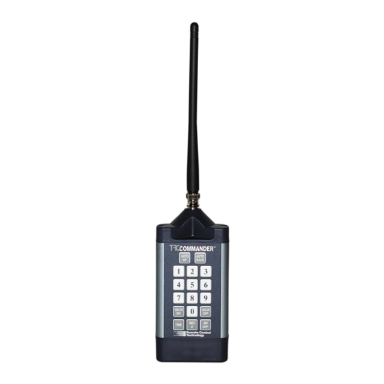
Remote Control Technology product users who appreciate the im- portance of high standards, product quality and timely service. The new TRC Commander is RCT's 6th generation of remote con- trol products introduced since 1982. All of our remote control prod- ucts do not require site surveys, base stations or FCC licensing. - Page 4 Models and Description Transmitter TRC Commander Transmitter is the hand-held part of your remote system. Any 24VAC solenoid valve sprinkler system equipped with a TRC Universal Receiver or TRC Permanent Receiver Card can be operated with this Transmitter. The Trans- mitter operates on one 9-volt alkaline replacable battery.
-
Page 5: Special Features
Special Features • Connects to any 24VAC sprinkler system • Silent Running -Turn off all of the zones from 1 - 7 days • Adjustable Time Duration -2 Minutes to 2 Hours (default 20 minutes) • Multiple Receiver operation from a single Transmitter - Field programmable dipswitches offer 199 unique Receiver numbers •... -
Page 6: Getting To Know The Transmitter
Getting To Know The Transmitter The TRC Commander Transmitter sends a proprietary FM sig- nal to the Commander Receiver(s) turning on or off selected valves. With each valve activation or deactivation, the Pump Start/Master Valve station, when used, is automatically turned on or off unless "MV Off"... - Page 7 The Transmitter Key Pad The Commander Transmitter keypad has an audible beep to clearly indicate when a key is pressed. The Transmitter will beep once when a Number Key or the Receiver Number Key is pressed. The Transmitter will beep twice, with about two sec- onds between beeps, after a transmit key is pressed for ("VALVE ON", "VALVE OFF", "AUTO UP", "AUTO BACK", "M-V OFF"...
- Page 8 Transmitter Operating Instructions Error Tone You will hear a squak error tone if an incorrect series of keys have been pressed. When the error tone is heard, wait 10 seconds and simply restart the series of commands. Low Battery Tone A rapid sequence of beeps after the transmission beep indicates low battery power.
- Page 9 Auto Up/Auto Back These functions allow forward and backward advancement through each station. This will turn on the next sequential station number. AUTO AUTO To operate press: BACK Multiple Zones Press the "9" key before a two digit zone number to turn on a multipe zone.
- Page 10 Time Duration You can set a time duration anywhere from two minutes to two hours. Press three digits of time in the following format: Hour, Tens Minutes, Minutes. The range of allowed entries for time duration is from two minutes "002" to two hours "200". Then press the "Time"...
- Page 11 VALVE To turn Master Valve on: Receiver Number The TRC Commander Transmitter can operate as many as 199 Permanent Receivers on each group code. To designate Receiver press a desired Receiver number and "Rec #" key. Setting to Receiver number 3:...
- Page 12 Silent Running Feature (Rain Off) This feature allows user to shut down the controller remotely by disconnecting valve common similar to a rain switch. The con- troller can be disabled for 1 to 7 days or indefinitely. The Receiver Card interrupts the signal from the controller to the valves and shuts the system down without having to change pro- gramming.
- Page 14 Setting The Receiver’s Dip Switches YOU DO NOT NEED TO CHANGE ANYTHING TO MAKE YOUR UNITS OPERATE! The units come from the factory set on Group Code 1, Receiver # 1. If you change the dipswitches, you must reprogram you transmitter to the same settings, as explained on the previous page.
- Page 15 EXAMPLE 1: Factory Default - Universal Receiver shown Group Code Switch Set is switched to Group Code #1, Receiver Switch Set is switched to Receiver #1 Group Code Switch Set Receiver # Switch Set EXAMPLE 2: Factory Default - Permanent Receiver Card shown Group Code Switch Set is switched to Group Code #1, Receiver Switch Set is switched to Receiver #1 Group Code Switch Set...
-
Page 16: Installation Instructions
Receiver Card for the Rain Bird ESP MC Installation Instructions: Step 1: Remove power from controller first! Step 2: Unplug the ribbon cable from the main circuit board. Step 3: Connect the Receiver Card into the socket on the main circuit board where the ribbon cable was removed from. - Page 17 Receiver Card for the Rain Bird ESP LX Installation Instructions: Step 1: Remove power from controller first! Step 2: Unplug the ribbon cable from the main circuit board. Step 3: Connect the Receiver Card into the socket on the main circuit board where the ribbon cable was removed from.
- Page 18 Receiver Card for the Hunter Installation Instructions: Step 1: Remove power from controller first! Step 2: Open the front panel door of the controller and clean the bottom inner portion of the door. Step 3: Remove the backing paper from the double-sided tape on the back of the Receiver Card and firmly place the Card onto the spot you have just cleaned.
- Page 19 Receiver Cards for the Superior Sterling Installation Instructions: Step 1: Remove power from controller first! Step 2: Remove the controller faceplate by unscrewing the cross-recessed screws on each side. Step 3: Clean upper left, inner side panel (inside controller, behind front panel).
- Page 20 Receiver Cards for the Irritrol MC and Dial Installation Instructions: Step 1: Remove power from controller first! Step 2: Remove the controller faceplate by unscrewing the cross-recessed screws on each side. Step 3: Clean upper left, inner side panel (inside controller, behind front panel).
- Page 21 Receiver Cards for the HIT Logic 2 and Hit Logic 3 Controller Installation Instructions: Step 1: Remove power from controller first! Step 2: Remove the controller's lower faceplate by removing the screws on each side. Step 3: Clean lower right, inner side panel (inside controller, behind front panel).
- Page 22 Installing The Universal Receiver Connecting the TRC Commander Receiver The TRC Commander works with any 24 VAC solenoid valve sprin- kler system. The TRC Commander Receiver connects to individual valves at the controller's terminal strip or directly to the valve wires at the controller, and bypasses the controller's functions by directly activating the valves.
- Page 23 Wiring Your PCC Instructions also provided with PCC. Warning Do not have the Receiver plugged into connector cable while installing connector or damage may occur. Do not have 24VAC transformer plugged into Receiver with the connector when the connector has 24VAC from the controller! Step 1: Step 1:...
- Page 24 CONNECTED TO 37-PIN CLAMSHELL BEFORE CONNECTING DCI-2 CABLE TO CONTROLLER. First connect the 37-pin clamshell directly to the TRC Commander Receiver. To operate the Receiver, attach the DCI-2 circular plug to the DCI-1 connector at the controller knockout location. Align pins and twist connector on with a clockwise motion.
- Page 25 DCI-2 cable from the controller, twist the circular plug in a counter- clockwise motion and remove from the DCI-1 cable. Remove the 37-pin clamshell from TRC Commander Receiver and store the cable in carrying case when not in use. Extreme care should be taken with the DCI-2 cable to safeguard the in- tegrity of its circuitry.
-
Page 26: Troubleshooting Chart
Trouble Shooting Chart Use the following chart to determine if your problem can be corrected in the field. If you have a problem that cannot be fixed in the field: • Call the toll free Remote Control Technology Customer Service number (800) 275-8558 and •... - Page 27 Fault Indication Correction Check if the Receiver number was inadvertently Receiver fails to changed. Reprogram the Transmitter codes to match respond, but the the Receiver codes. (Press "1", "REC #") power light is on. Check the Group Code and Receiver Code dipswitches on the Receiver.
- Page 28 32 Station Connector Wiring Color Codes Valve Wire Color Valve Wire Color Black Green w/ black and white stripe White Orange w/ black and white stripe Blue w/ black and white stripe Green Black w/ red and green stripe Orange White w/ red and green stripe Blue Red w/ black and green stripe...
Need help?
Do you have a question about the UNIVERSAL IRRIGATION REMOTE CONTROL and is the answer not in the manual?
Questions and answers