Table of Contents
Advertisement
Advertisement
Table of Contents

Subscribe to Our Youtube Channel
Related Manuals for Clinton Electronics VF540


Summary of Contents for Clinton Electronics VF540
- Page 3 The lightning flash with an arrowhead symbol, within an equilateral triangle is intended to alert the user to the presence of uninsulated dangerous voltage within the product’s enclosure that may be of sufficient magnitude to constitute a risk of electric shock to persons. The exclamation point within an equilateral triangle is intended to alert the user to the presence of important operating and maintenance (servicing) instructions in the literature accompanying the appliance.
-
Page 4: Table Of Contents
Table of Contents Warning ………………………………………………………………………………1 Precautions ……………………………………………………………………………2 Components……………………………………………………………………………4 Camera Components …………………………………………………………………5 Installation …………………………………………………………………………… 6 Bracket & Camera Mounting Power Connector & Monitor Impedance Viewing Angle & Focus Adjustment Sunshield Mounting Remote Control On Screen Display (OSD) Menu ………………………………………………………7 Accessing the OSD Menu Settings . ………………………………………………… 8 •... -
Page 5: Warning
Warning The camera requires periodic inspection. Contact an authorised technician to carry out the inspection. Stop using your camera if malfunction occurs. If the camera emits smoke or is unusually hot for a long period, a fire may result. Unplug device immediately if device exhibits these symptoms. Do not install the camera on a surface that can not support it. -
Page 6: Precautions
Precautions Do not install the camera in Do not install the camera under extreme temperature conditions. unstable lighting conditions. Only use the camera under conditions Severe lighting change or flicker can where temperatures are between cause the camera to work improperly. -20°F ~ 122°F. - Page 7 Do not drop the camera or subject Never keep the camera pointed it to physical shocks. directly at strong light. It can cause malfunctions to occur. It can damage the CCD. Do not expose the camera to radioactivity. If exposed to radioactivity the CCD will fail.
-
Page 8: Components
Components Sales: 1-800-447-3306 Support: 1-800-549-6393 www.clintonelectronics.com... -
Page 9: Camera Components
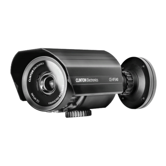
Camera Components 5. Plug-in port for CE-REMOTE 1. Cable 6. Zoom adjustment 2. Mounting Plate 7. Focus adjustment 3. Arm 8. DC Auto Iris Vari-Focal lens 4. Case 9. Sunshield Sales: 1-800-447-3306 Support: 1-800-549-6393 www.clintonelectronics.com... -
Page 10: Installation
Installation mounting plate Sunshield mounting screws cable routing: center or side camera arm screws focus zoom Remote port 1. Bracket & Camera Mounting - Affix the bracket to the mounting surface. - Run cables through the center of the mounting bracket, or out the side slot. 2. -
Page 11: On Screen Display (Osd) Menu
On Screen Display (OSD) Menu • On Screen Display (OSD) Menu Camera functions and settings can be adjusted or changed by activating the OSD menu. When the OSD menu is activated text will display on the monitor. The user can then move the cursor to the desired function to change the setting. SETUP Menu LENS • DC... -
Page 12: Accessing The Osd Menu Settings
Accessing the OSD Menu Settings Settings can be adjusted by using the optional CE-REMOTE (Sold separately). 1. Plug the CE-REMOTE into the port located at the bottom of the camera. Power input BNC output to test monitor plug-in remote connection 2. - Page 13 3. Select a menu item from the list available by using the UP and DOWN buttons. • Functions are selected using up and down buttons. • Place the cursor over a desired item, the selected position is displayed. When an arrow is present, press Select the function SETUP button to using the UP or enter sub-menu DOWN button. Change the status using the LEFT or RIGHT button.
-
Page 14: Lens
LENS (Adjusting the brightness level) Using this function, you can control the screen brightness. 1. When the SETUP menu screen is displayed, select ‘LENS’ by using the Up and Down buttons so that the arrow indicates ‘LENS’ . DC: You can adjust the minimum shutter and maximum value of ... -
Page 15: Exposure
EXPOSURE 1. When the SETUP menu is displayed, select ‘EXPOSURE’ by using the Up and Down buttons so that the arrow indicates ‘EXPOSURE’ . Press SETUP to enter. 2. Select the desired mode using Up and Down buttons. BRIGHTNESS: Adjusts the exposure brightness. ... - Page 16 aSHUTTER continued Notes • When using a DC lens, set the shutter mode to A.FLK if color rolling occurs. • When the SHUTTER is set to ESC after selecting Internal Synchronization Type, the picture may become unstable if the camera faces a bright fluorescent light. Therefore, take care when choosing the installation position. • When the SHUTTER is set to MANUAL or A.FLK mode, SENS-UP will be disabled. AGC (AUTO GAIN CONTROL) : The higher the gain level, the brighter ...
-
Page 17: White Balance
White Balance control Use the White Balance function to adjust the screen color. 1. When the SETUP menu screen is displayed, select ‘WHITE BAL’ by using the Up and Down buttons so that the arrow indicates ‘WHITE BAL’ . 2. Select a desired mode using the Left and Right buttons. t Select one of the following 5 modes, as appropriate for your purpose. -
Page 18: Ssdr (Super Dynamic Range)
SSDR (Super Dynamic Range) SSDR illuminates darker areas of an image while retaining the same light level for brighter areas to even out the overall brightness of images with high contrast between bright and dark areas. 1. When the SETUP menu screen is displayed, select ‘SSDR’ by using the Up and Down buttons so that the arrow indicates ‘SSDR’... -
Page 19: Blc (Back Light Compensation)
BLC (Back Light Compensation) 1. When the SETUP menu screen is displayed, select ‘BACKLIGHT’ by using the Up and Down buttons so that the arrow indicates ‘BACKLIGHT’ . 2. Select a desired mode using the Left and Right buttons depending on the camera purpose. - Page 20 continued H LC HLC MASKING AREA HLC ON HLC OFF OFF : Not being used. 3. Select a desired mode using the Left and Right buttons and press the SET button. BLC : Select ‘BLC’ to adjust HLC : Enable the user to ...
-
Page 21: Dnr3
DNR3 This function reduces the background noise in a low luminance environment. 1. When the SETUP menu screen is displayed, select ‘DNR’ by using the Up and Down buttons so that the arrow indicates ‘DNR’ . 2. Select a desired mode using the Left and Right buttons. OFF : Deactivates DNR. -
Page 22: Day/Night
Day/Night You can display pictures in color or black and white. 1. When the SETUP menu screen is displayed, select ‘DAY/NIGHT’ by using the Up and Down buttons so that the arrow indicates ‘DAY/NIGHT’ . 2. Select a desired mode using the Left and Right buttons according to the picture display you want. -
Page 23: Special
Special 1. When the SETUP menu screen is displayed, select ‘SPECIAL’ by using the Up and Down buttons so that the arrow indicates ‘SPECIAL’ . Press SETUP to enter the ‘SPECIAL’ menu. 2. Select a desired mode using the Up and Down buttons. IMAGE ADJ. -
Page 24: Image Adj
continued I MAGE ADJ. Notes • As the DIS function uses the digital zoom the camera’s resolution will decrease. • DIS doesn’t operate when background illumination is too low. • DIS doesn’t operate when object pattern is monotonic (ie. sky or white wall). FONT COLOR : You can change the OSD font color. -
Page 25: Cam Title
CAM TITLE : If you enter a title, the title will appear on the monitor. 1) If the SPECIAL menu screen is displayed, use the Up and Down buttons so that the arrow indicates ‘CAM TITLE’ . 2) Set it to ‘ON’ by using the Left and Right buttons. - Page 26 SYNC : In areas where the supply is at 60Hz, you can synchronize the output phase of multiple cameras using the power synchronization function (Line-Lock) without using a synchronization signal generator. – INT : Internal Synchronization Type – L/L : Power Synchronization Type, Line-lock Press the Function Setup switch.
-
Page 27: Motion Det
continued M OTION DET 2) Set up the mode using the 4 direction buttons. – SENSITIVITY : You can select up to 8 MD areas. When SENSITIVITY number is high, motion detection sensitivity is increased to recognize even small movement. –... -
Page 28: Privacy
continued P RIVACY 2) Set up the mode using the 4 direction buttons. – AREA SEL : Select up to 12 PRIVACY areas. – MODE : Determines whether to use the area selected in the AREA SEL. – MASK COLOR : Determines area color. Select Green, Red, Blue, Black, White, Gray. -
Page 29: Comm Adj
continued C OMM ADJ 2) Set up the mode using the 4 direction buttons. – CAM ID : Determines the camera’s identification number (between 0 and 255). – BAUD RATE : Select 2400/4800/9600/19200/38400/57600 bps. – UART MODE : Select NONE, EVEN or ODD for the parity bits. –... -
Page 30: Troubleshooting
Troubleshooting If you have trouble operating your camera, refer to the following table. If the guidelines do not enable you to solve the problem, contact Clinton Electronics Technical Support at 1-800-549-6393 or 815-633-1444. Problem Solution Nothing appears on • Check the power connection. - Page 31 Troubleshooting Problem Solution The MOTION DETECTION • Check if ‘MOTION DETECTION’ mode is function is not working. turned on. • Check if the MD LEVEL is too low. • Check the setting of the MD AREA. Colors are not quite right. •...
-
Page 32: Specifications
Specifications Camera CE-VF540 Image Sensor 1/3 Inch SONY Super HAD CCD Resolution 600 TV Lines Effective Pixels 768 (H) x 494 (V) Scanning System 2:1 Interlace S/N Ratio 52dB (AGC Off, Weight On) Sync System Internal / Line Lock Scanning Frequency 15.734 KHz (H), 59.94 Hz (V) Minimum Illumination 0.000006 Lux (Sense-Up *258x &... - Page 33 Dimensions 3.94” 2.91” 8.50” 6.10” CLINTON Electronics CE-VF540 4.72” Sales: 1-800-447-3306 Support: 1-800-549-6393 www.clintonelectronics.com...
- Page 34 v.12.15.10...
Need help?
Do you have a question about the VF540 and is the answer not in the manual?
Questions and answers