Table of Contents
Advertisement
Quick Links
Owner's Manual
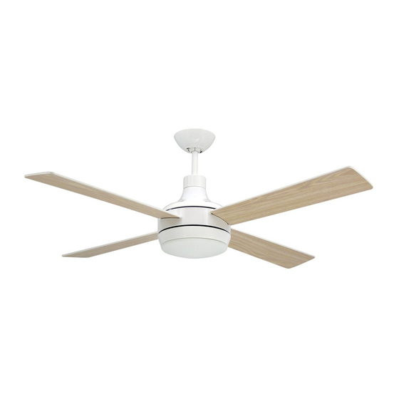
Quantum
This instruction contains 5 pages:
Page 1: Foreword
Page 2: Unpack and inspect parts contained
Page 3: Notes before installation and
Page 4:
Page 5: C
Page 6: Remote & Setting
3110124
Toll Free: 1-855-676-7247
WARNING : Read and follow these instructions carefully and be mindful of all warnings shown throughout.
4UFOD52+LK+C
Cap for non-light use
anopy / Blade / Light kit installation
Hanging system installation
Net weight
8.0 KGS.
17.6 LBS.
Advertisement
Table of Contents

Related Manuals for TroposAir Quantum 4UFOD52+LK+C


Summary of Contents for TroposAir Quantum 4UFOD52+LK+C
- Page 1 Owner’s Manual Quantum 4UFOD52+LK+C Cap for non-light use This instruction contains 5 pages: Page 1: Foreword Page 2: Unpack and inspect parts contained Page 3: Notes before installation and Hanging system installation Page 4: Wire connection Page 5: C anopy / Blade / Light kit installation Page 6: Remote &...
- Page 2 READ AND SAVE THESE INSTRUCTIONS WARNING : TO REDUCE THE RISK OF FIRE, ELECTRICAL SHOCK, OR INJURY TO PERSONS, PLEASE OBSERVE THE FOLLOWING : 1]. To ensure the success of the installation, be sure to read the instructions and review the diagrams thoroughly before beginning.
- Page 3 Unpack and inspect fan carefully to be certain all contents are included. Mounting Bracket Hardware Bag For Mounting Bracket: Flat Washer x2 Spring Washer x2 Machine Screw x2 Wood Screw x2 Downrod For Wire Connection: Assembly Wire Nut x 3 For Blade Installation: Blade Screw x 9 (one spare screw included)
-
Page 4: Hanging The Fan
WARNING: blades should be at least 7 feet from floor Note 1: Note 2: Turn off power at breaker Use metal outlet box suitable box to avoid possible for fan support. electrical shock. Outlet box must support 35 lbs min. O FF O FF O 1. - Page 5 2. WIRE CONNECTION 2A. Insert receiver into mounting bracket NOTE: Do not sq eeze all the wires while inserting the receiver into the mounting bracket. Receiver Mounting Bracket 2B. Making electrical wire connection Follow diagram below and make sure that all exposed wires are secured inside wire nuts. Note: Wires from house may vary in color and may not include ground wire (green).
- Page 6 3. CANOPY INSTALLATION Note: Two screws are pre-installed on mounting bracket for canopy installation. Push up canopy until two screws pre-screwed on mounting bracket are engaged with two key holes on canopy. Rotate canopy slightly until two pre-installed screw heads are engaged in the narrow end of key holes. Tighten both screws.
- Page 7 6. REMOTE & SETTING SETTING for light operation before starting fan. Pressing the button “OFF” for 3~5 seconds till the LIGHT BLINKS , which means this remote control has done the setting. Now the remote is ready for operation. D: for light dimming (for incandescent bulbs) LOW:Fan low speed MED:Fan middle speed...
Need help?
Do you have a question about the Quantum 4UFOD52+LK+C and is the answer not in the manual?
Questions and answers