Table of Contents
Advertisement
Quick Links
Advertisement
Table of Contents

Related Manuals for Crestron DigitalMedia DM-MD6X1


Summary of Contents for Crestron DigitalMedia DM-MD6X1
- Page 1 Crestron DM-MD6X1 6X1 DigitalMedia™ Switcher Operations Guide...
-
Page 2: Regulatory Compliance
Cet appareil numérique de la classe B est conforme à la norme NMB-003 du Canada. This device includes an aggregation of separate independent works that are each generally copyrighted by Crestron Electronics, Inc., with all rights reserved. One of those independent works, Linux Bridge Project, is copyrighted under the GNU GENERAL PUBLIC LICENSE, Version2, reproduced in “GNU General Public License”... -
Page 3: Table Of Contents
Crestron DM-MD6X1 6X1 DigitalMedia™ Switcher Contents 6X1 DigitalMedia™ Switcher: DM-MD6X1 Introduction ..........................1 Features and Functions ....................1 Applications......................... 4 Internal Block Diagram ....................5 Specifications ......................6 Physical Description....................10 Setup ............................16 Network Wiring......................16 HDCP Signal Path ..................... 16 Ethernet Setup ...................... -
Page 5: 6X1 Digitalmedia™ Switcher: Dm-Md6X1
DM-MD6X1, providing a perfect standalone switcher or multiformat interface for installation in an equipment rack or presentation lectern. Additional DigitalMedia inputs and output allow the DM-MD6X1 to work with the ® full line of Crestron DM transmitters, switchers, receivers, and room controllers, affording extensive capabilities for routing and distributing all of today’s multimedia... - Page 6 1. For DigitalMedia CAT wiring, use DM-CBL DigitalMedia Cable. Up to two DM Repeaters (model DM-DR, sold separately) may be required. Refer to the latest version of the Creston DigitalMedia Design Guide (Doc. 4789) for complete wiring guidelines. It is available from the Crestron Web site (www.crestron.com/dmresources).
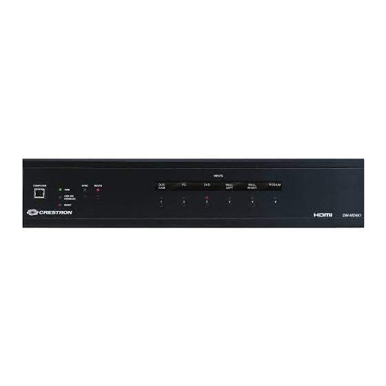
- Page 7 DigitalMedia allows you to take control of each device in the system as you like. Easy Setup The DM-MD6X1 is designed to be placed on a shelf or mounted in an equipment rack or lectern. The front panel provides basic operation right out of the box.
-
Page 8: Applications
, and the CEN-RGBHV Series (all sold separately). A simple HD15 VGA cable connected between the output of an MPS system and the input of the DM-MD6X1 allows every RGB, component, S-video, and composite video input on the MPS to be converted to DigitalMedia*. -
Page 9: Internal Block Diagram
The following diagram represents the signal path through the DM-MD6X1. Internal Block Diagram of the DM-MD6X1 The following table shows valid audio breakaway routes through the DM-MD6X1. If an invalid route is established, video will be transmitted but audio will not. -
Page 10: Specifications
6X1 DigitalMedia™ Switcher Crestron DM-MD6X1 Specifications Specifications for the DM-MD6X1 are listed in the following table. DM-MD6X1 Specifications SPECIFICATION DETAILS Video Switcher 6x1 combination digital/analog switch, Crestron QuickSwitch HD Input Signal Types DM CAT (DigitalMedia over shielded twisted-pair copper wire), HDMI, DVI... - Page 11 Formats, HDMI and S/PDIF Dolby Digital, Dolby Digital EX, DTS DTS-ES, DTS 96/24, 2ch PCM Formats, HDMI only Up to 8ch PCM Formats, Analog Stereo 2-Channel (Continued on following page) 6X1 DigitalMedia™ Switcher: DM-MD6X1 • 7 Operations Guide – DOC. 6850D...
- Page 12 Metal with black finish, vented sides, fan-cooled Faceplate Extruded aluminum, black finish with polycarbonate label overlay Mounting Freestanding or 2U 19-inch rack-mountable (adhesive feet and rack ears included) (Continued on following page) 8 • 6X1 DigitalMedia™ Switcher: DM-MD6X1 Operations Guide – DOC. 6850D...
- Page 13 DM IN 6 audio may each be switched freely except when any other numbered DM IN video input is selected; AUDIO IN 1 and SPDIF IN 1 inputs are mutually exclusive. 4. The latest software versions can be obtained from the Crestron Web site. Refer to the NOTE following these footnotes.
-
Page 14: Physical Description
38400 (Cresnet speed) or lower. Otherwise, Toolbox may post the “Transfer Failed” message. NOTE: Crestron software and any files on the Web site are for authorized Crestron dealers and Crestron Authorized Independent Programmers (CAIP) only. New users may be required to register to obtain access to certain areas of the site (including the FTP site). - Page 15 Crestron DM-MD6X1 6X1 DigitalMedia™ Switcher DM-MD6X1 Overall Dimensions (Top View) DM-MD6X1 Overall Dimensions (Rear View) 6X1 DigitalMedia™ Switcher: DM-MD6X1 • 11 Operations Guide – DOC. 6850D...
- Page 16 (3) DM CAT inputs, each composed of (2) 8-pin RJ-45 female, shielded; Connect to DM CAT outputs of DM transmitters or other DM devices via DM-CBL cable (Continued on following page) 12 • 6X1 DigitalMedia™ Switcher: DM-MD6X1 Operations Guide – DOC. 6850D...
- Page 17 (1) 5-pin 3.5 mm detachable terminal block; Balanced/unbalanced stereo line-level output, variable level; Output Impedance: 200 Ohms balanced, 100 Ohms unbalanced Maximum Output Level: 4 V balanced, unbalanced (Continued on following page) 6X1 DigitalMedia™ Switcher: DM-MD6X1 • 13 Operations Guide – DOC. 6850D...
- Page 18 COMPOSITE Comp 3. The RGB input can accept component, composite and S-video signals via direct interface to Crestron MPS Series products (sold separately) or through an appropriate adapter (not included). Input sync detection is not provided for composite or S-video signal types through the RGB connection.
- Page 19 10. If a DM switcher or other DM device is supplying power and is connected to a DM port of the DM-MD6X1 or other DM midpoint, then the +24V wire between the DM device and the DM-MD6X1 must be disconnected. The A B G wires must remain connected.
-
Page 20: Setup
The DM-MD6X1 can also use high-speed Ethernet for communications between the device and a control system, computer, media server and other IP-based devices. For general information on connecting Ethernet devices in a Crestron system, refer to the latest version of the Crestron e-Control Reference Guide (Doc. -
Page 21: Ethernet Setup
Example: A DM-MD6X1 is set to IP address 192.168.1.30. The IP mask is 255.255.255.0 and the default router is 192.168.1.1. The HDMI input card on slot 3 would be set to IP 6X1 DigitalMedia™ Switcher: DM-MD6X1 • 17... -
Page 22: Identity Code
The IP ID is set within the DM-MD6X1’s table using Crestron Toolbox. For information on setting an IP table, refer to the Crestron Toolbox help file. The IP IDs of multiple DM-MD6X1 devices in the same system must be unique. - Page 23 Stacking Four “feet” are provided with the DM-MD6X1 so that if the unit is not rack mounted, the rubber feet can provide stability when the unit is placed on a flat surface or stacked. These feet should be attached prior to the hookup procedure.
-
Page 24: Hardware Hookup
6X1 DigitalMedia™ Switcher Crestron DM-MD6X1 Foot Placement for the DM-MD6X1 Place Feet in Corners NOTE: No more than two DM-MD6X1 units should be stacked. Hardware Hookup Connect the Device Make the necessary connections as called out in the illustration that follows this paragraph. - Page 25 NOTE: If a DM Switcher, or other DM device supplying power, is connected to a DM IN 4-6 port of the DM-MD6X1, then the +24V wire between the DM device and the DM-MD6X1 must be disconnected. The A B G wires must remain connected.
- Page 26 1 + Out 1 – signal return, Open jumper to GND Shield/Ground Shield/Ground Ground Common ground 2 + In 2 + Out 2 – signal return Open jumper to GND 22 • 6X1 DigitalMedia™ Switcher: DM-MD6X1 Operations Guide – DOC. 6850D...
- Page 27 Shield Label the Buttons Use Crestron Engraver software to print custom labels for the DM-MD6X1’s front panel buttons and LEDs. Crestron recommends printing on 100-pound paper. Paper weighing less than 100 pounds will tend to crumple while sliding in, while paper weighing more than 100 pounds may not fit.
-
Page 28: Programming Software
Have a question or comment about Crestron software? Answers to frequently asked questions (FAQs) can be viewed in the Online Help section of the Crestron Web site. To post a question or view questions you have submitted to Crestron’s True Blue Support, log in at www.crestron.com/support. - Page 29 IP ID as shown in the following illustration. C2ENET-1 Device, Slot 8 2. If additional DM-MD6X1 devices are to be added, repeat step 1 for each device. Each DM-MD6X1 is assigned a different IP ID number as it is added.
- Page 30 To configure a SIMPL Windows program for this layout, drop a DM-TX-100, DM-TX-200, DM-RMC-100 or DM-RMC-200 (as appropriate, all sold separately) onto the slots that are on the DM-MD6X1 as shown in the illustration below. The IP table of each device will be automatically configured and uploaded.
- Page 31 Devices Placed on Ethernet Port on Control System Program Manager Program Manager is the view where programmers “program” a Crestron control system by assigning signals to symbols. The symbol can be viewed by double clicking on the icon or dragging it into Detail View.
-
Page 32: Uploading And Upgrading
USB. Via USB Port USB Communication To establish USB communication between the PC and the DM-MD6X1 via a DM switcher: 1. Use the Address Book in Crestron Toolbox to create an entry using the expected communication protocol (USB). When multiple USB devices are connected, identify the DM-MD6X1 by entering “DM-MD6X1”... -
Page 33: Programs And Firmware
To establish TCP/IP communication between the PC and the DM-MD6X1 via the LAN port of the DM-MD6X1: 1. Use the Device Discovery Tool in Crestron Toolbox to find the IP address of the DM-MD6X1. The tool is available in Toolbox version 1.15.143 or later. -
Page 34: Program Checks
3. A defined IP table can be saved to a file or sent to the device. Edit the control system’s IP table to include an entry for the DM-MD6X1. The entry should list the DM-MD6X1’s IP ID (specified on the DM-MD6X1’s IP table) and the internal gateway IP address 127.0.0.1. -
Page 35: Operation
Crestron DM-MD6X1 6X1 DigitalMedia™ Switcher Operation The DM-MD6X1 operates in Sync mode and Route mode by using the front panel buttons. Sync Mode Pressing the SYNC button on the front panel will light the LEDs for inputs where the same signal type is present. -
Page 36: Problem Solving
(switch or endpoint). Loss of video. Various causes. Use DM Tool to determine cause and correct accordingly. NOTE: For more advanced diagnostics, use the DMTool in Crestron Toolbox. 32 • 6X1 DigitalMedia™ Switcher: DM-MD6X1 Operations Guide – DOC. 6850D... -
Page 37: Check Network Wiring
Use the Right Wire To ensure optimum performance over the full range of your installation topology, use Crestron Certified Wire only. Failure to do so may incur additional charges if support is required to identify performance deficiencies because of using improper wire. -
Page 38: Reference Documents
Crestron's award winning customer service team by calling Crestron at 1-888-CRESTRON [1-888-273-7876]. You can also log onto the online help section of the Crestron Web site (www.crestron.com/onlinehelp) to ask questions about Crestron products. First-time users will need to establish a user account to fully benefit from all available features. -
Page 39: Return And Warranty Policies
Purchasers should inquire of the dealer regarding the nature and extent of the dealer's warranty, if any. CRESTRON shall not be liable to honor the terms of this warranty if the product has been used in any application other than that for which it was intended or if it has been subjected to misuse, accidental damage, modification or improper installation procedures. -
Page 40: Gnu General Public License
License and to the absence of any warranty; and give any other recipients of the Program a copy of this License along with the Program. 36 • 6X1 DigitalMedia™ Switcher: DM-MD6X1 Operations Guide – DOC. 6850D... - Page 41 5. You are not required to accept this License, since you have not signed it. However, nothing else grants you permission to modify or distribute the Program or its derivative works. These actions are prohibited by law if you do not accept this License. Therefore, by 6X1 DigitalMedia™ Switcher: DM-MD6X1 • 37 Operations Guide – DOC. 6850D...
- Page 42 THIRD PARTIES OR A FAILURE OF THE PROGRAM TO OPERATE WITH ANY OTHER PROGRAMS), EVEN IF SUCH HOLDER OR OTHER PARTY HAS BEEN ADVISED OF THE POSSIBILITY OF SUCH DAMAGES. 38 • 6X1 DigitalMedia™ Switcher: DM-MD6X1 Operations Guide – DOC. 6850D...
- Page 43 Crestron DM-MD6X1 6X1 DigitalMedia™ Switcher This page is intentionally left blank. 6X1 DigitalMedia™ Switcher: DM-MD6X1 • 39 Operations Guide – DOC. 6850D...
- Page 44 Crestron Electronics, Inc. Operations Guide – DOC. 6850D 15 Volvo Drive Rockleigh, NJ 07647 (2024730) Tel: 888.CRESTRON 02.11 Fax: 201.767.7576 Specifications subject to www.crestron.com change without notice.
Need help?
Do you have a question about the DigitalMedia DM-MD6X1 and is the answer not in the manual?
Questions and answers