Crestron DigitalMedia DM-MD64X64 Operations & Installation Manual
Digitalmedia switchers
Hide thumbs
Also See for DigitalMedia DM-MD64X64:
- Operations & installation manual (60 pages) ,
- Supplemental manual (44 pages) ,
- Quick start (5 pages)

Related Manuals for Crestron DigitalMedia DM-MD64X64


Summary of Contents for Crestron DigitalMedia DM-MD64X64
- Page 1 Crestron DM-MD64X64/ DM-MD128X128 DigitalMedia™ Switchers Operations & Installation Guide...
- Page 2 Crestron, the Crestron logo, AIR, Auto-Locking, CresFiber, Crestron Studio, DigitalMedia, DigitalMedia 8G, DigitalMedia 8G+, DM, DM 8G, DM 8G+, e-Control, Fusion RV, and QuickSwitch HD are either trademarks or registered trademarks of Crestron Electronics, Inc. in the United States and/or other countries. Blu-ray Disc is either a trademark or registered trademark of the Blu-ray Disc Association (BDA) in the United States and/or other countries.
-
Page 3: Regulatory Compliance
Regulatory Compliance As of the date of manufacture, the DM-MD64X64 and DM-MD128X128 have been tested and found to comply with specifications for CE marking. Federal Communications Commission (FCC) Compliance Statement This device complies with part 15 of the FCC Rules. Operation is subject to the following conditions: (1) This device may not cause harmful interference and (2) this device must accept any interference received, including interference that may cause undesired operation. -
Page 5: Table Of Contents
Input Blades ....................... 43 Output Blades ......................58 Return and Warranty Policies ....................74 Merchandise Returns / Repair Service ..............74 Crestron Limited Warranty ..................74 GNU General Public License ....................75 Operations & Installation Guide – DOC. 7318D Contents • i... -
Page 7: Digitalmedia Switchers: Dm-Md64X64/Dm-Md128X128
• Supports up to 64 DM 8G transmitters and 64 DM 8G receivers (DM-MD64X64) or up to 128 DM 8G transmitters and 128 DM 8G receivers (DM-MD128X128) (Continued on following page) 1. Onboard HDMI output and analog audio input and output are future features that will be enabled through a future output blade and other components. - Page 8 1080p. DM 8G+ is compatible with HDBaseT Alliance specifications for connecting to HDBaseT compliant equipment. 3. For complete system design guidelines, refer to the Crestron DigitalMedia Design Guide (Doc. 4546) at www.crestron.com/dmresources. All wire and cables sold separately. 4. The maximum DigitalMedia 8G fiber (DM 8G fiber) cable length is 1000 feet (300 meters) using CRESFIBER8G fiber optic cable or 500 feet (150 meters) using standard CRESFIBER, CRESFIBER-SINGLE-SC, or third-party OM3 simplex multimode fiber optic cable.
- Page 9 1080p. DM 8G+ is compatible with HDBaseT Alliance specifications for connecting to HDBaseT compliant equipment. 5. For complete system design guidelines, refer to the Crestron DigitalMedia Design Guide (Doc. 4546). All wire and cables sold separately. 6. The maximum DigitalMedia 8G fiber (DM 8G fiber) cable length is 1000 feet (300 meters) using CRESFIBER8G fiber optic cable or 500 feet (150 meters) using standard CRESFIBER, CRESFIBER-SINGLE-SC, or third-party OM3 simplex multimode fiber optic cable.
- Page 10 330 feet (100 meters). Modular Architecture The DM-MD64X64 features a modular architecture with 8 input blade slots and 8 output blade slots; the DM-MD128X128 features a modular architecture with 16 input blade slots and 16 output blade slots. Each blade slot on the DM switchers are field installable, allowing for easy and flexible system configuration with the ability to make changes to the system as needs change.
-
Page 11: Usb Switch
10/100 Ethernet to each display and source device via select DM receivers and transmitters (sold separately), providing high-speed connectivity for any room device that requires a LAN connection. Ethernet is also utilized internally by the Crestron control bus to manage all of the DM devices in the system and provide display control in each room. - Page 12 The DM switchers deliver enhanced reliability for mission-critical applications, employing hot-swappable redundant power supplies to ensure continuous operation throughout the life of the system. Two power supplies occupy the DM-MD64X64; three power supplies occupy the DM-MD128X128. Each of the onboard power supplies has a demonstrated MTBF (Mean Time Between Failures) of over a half million hours.
-
Page 13: Applications
Crestron DM-MD64X64/DM-MD128X128 DigitalMedia Switchers Applications The diagram below shows a DM-MD64X64 in a typical application. DM-MD64X64 in a Typical Application Operations & Installation Guide – DOC. 7318D DigitalMedia Switchers: DM-MD64X64/DM-MD128X128 • 7... -
Page 14: Specifications
Specifications for the DM switchers are listed in the following table. DM Switcher Specifications SPECIFICATION DETAILS Video Switcher 64 x 64 (DM-MD64X64) or 128 x 128 (DM-MD128X128) digital matrix, modular input/output blades, Crestron QuickSwitch HD Input Signal Types Configurable via modular plug-in blades supporting HDMI, DisplayPort Multimode,... - Page 15 SERVICE port, and (16) DM-MD64X64 or (32) DM-MD128X128 internal 1000 Mbps ports for the I/O blades plus (1) internal 10BASE-T/100BASE-TX port for the CPU USB Switch 64 x 64 (DM-MD64X64) or 128 x 128 (DM-MD128X128) matrix, follow video or breakaway Power Requirements Main Power DM-MD64X64: 16 A @ 100-127 Vac or 8 A @ 200-240 Vac, 50/60 Hz;...
- Page 16 DM-MD64X64: 24.44 in (621 mm) DM-MD128X128: 41.97 in (1066 mm) Width 19.00 in (483 mm) Depth DM-MD64X64: 16.26 in (413 mm) without I/O blades DM-MD128X128: 16.26 in (413 mm) without I/O blades, 19.55 in (497 mm) including front and rear handles Weight DM-MD64X64: 49.0 lb (22.3 kg) without I/O...
- Page 17 2. DM 8G+ and HDBaseT input is a future feature that will be enabled through a future input blade. 3. Onboard HDMI output and analog audio input and output are future features that will be enabled through a future output blade and other components. Operations & Installation Guide – DOC. 7318D DigitalMedia Switchers: DM-MD64X64/DM-MD128X128 • 11...
-
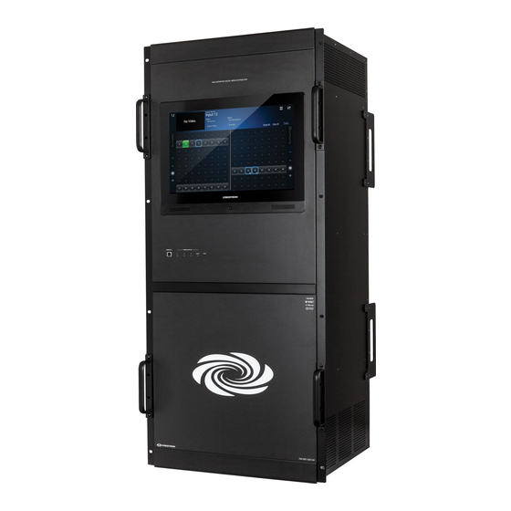
Page 18: Physical Description
DigitalMedia Switchers Crestron DM-MD64X64/DM-MD128X128 Physical Description This section provides information on the connections, controls, and indicators available on the DM switchers. DM-MD64X64 Physical View (Front) DM-MD64X64 Physical View (Rear) 12 • DigitalMedia Switchers: DM-MD64X64/DM-MD128X128 Operations & Installation Guide – DOC. 7318D... - Page 19 Crestron DM-MD64X64/DM-MD128X128 DigitalMedia Switchers DM-MD128X128 Physical View (Front) Operations & Installation Guide – DOC. 7318D DigitalMedia Switchers: DM-MD64X64/DM-MD128X128 • 13...
- Page 20 DigitalMedia Switchers Crestron DM-MD64X64/DM-MD128X128 DM-MD128X128 Physical View (Rear) 14 • DigitalMedia Switchers: DM-MD64X64/DM-MD128X128 Operations & Installation Guide – DOC. 7318D...
- Page 21 Crestron DM-MD64X64/DM-MD128X128 DigitalMedia Switchers DM-MD64X64 Overall Dimensions (Front View) 19.00 in (483 mm) 18.31 in (465 mm) 17.28 in (439 mm) 24.44 in 21.50 in 10.00 in (621 mm) (547 mm) (254 mm) 1.47 in (38 mm) Operations & Installation Guide – DOC. 7318D...
- Page 22 DigitalMedia Switchers Crestron DM-MD64X64/DM-MD128X128 DM-MD64X64 Overall Dimensions (Side View) 15.06 in (383 mm) 16 • DigitalMedia Switchers: DM-MD64X64/DM-MD128X128 Operations & Installation Guide – DOC. 7318D...
- Page 23 19.00 in (483 mm) 18.31 in (465 mm) 17.28 in (439 mm) 14.00 in (356 mm) 41.97 in (1066 mm) 11.00 in (280 mm) 14.00 in (356 mm) Operations & Installation Guide – DOC. 7318D DigitalMedia Switchers: DM-MD64X64/DM-MD128X128 • 17...
- Page 24 DigitalMedia Switchers Crestron DM-MD64X64/DM-MD128X128 DM-MD128X128 Overall Dimensions (Side View) 19.55 in (497 mm) 17.80 in (453 mm) 15.90 in (404 mm) 18 • DigitalMedia Switchers: DM-MD64X64/DM-MD128X128 Operations & Installation Guide – DOC. 7318D...
- Page 25 Crestron DM-MD64X64/DM-MD128X128 DigitalMedia Switchers DM-MD64X64 Connectors, Controls, and Indicators (Front View) Operations & Installation Guide – DOC. 7318D DigitalMedia Switchers: DM-MD64X64/DM-MD128X128 • 19...
- Page 26 DigitalMedia Switchers Crestron DM-MD64X64/DM-MD128X128 DM-MD64X64 Connectors, Controls, and Indicators (Rear View) 20 • DigitalMedia Switchers: DM-MD64X64/DM-MD128X128 Operations & Installation Guide – DOC. 7318D...
- Page 27 Crestron DM-MD64X64/DM-MD128X128 DigitalMedia Switchers DM-MD128X128 Connectors, Controls, and Indicators (Front View) Operations & Installation Guide – DOC. 7318D DigitalMedia Switchers: DM-MD64X64/DM-MD128X128 • 21...
- Page 28 DigitalMedia Switchers Crestron DM-MD64X64/DM-MD128X128 DM-MD128X128 Connectors, Controls, and Indicators (Rear View) 22 • DigitalMedia Switchers: DM-MD64X64/DM-MD128X128 Operations & Installation Guide – DOC. 7318D...
- Page 29 Pin 1 Pin 2 Data - Data + Ground POWER SUPPLIES (2 [DM-MD64X64] or 3 [DM-MD128X128]) (1-2 or 1-3) LEDs Green LEDs, indicate when each corresponding power supply is functioning POWER SUPPLIES (1) Red flashing LED, indicates a fault with...
- Page 30 (1) 6-32 screw, chassis ground lug 1. Although the DM-MD64X64 and DM-MD128X128 continue to operate if a single power supply fails, it is recommended that the failed power supply be replaced as soon as possible to restore power supply redundancy.
-
Page 31: Setup
The DM switchers also use high-speed Ethernet for communications between the device and a control system, computer, media server and other IP-based devices. For general information on connecting Ethernet devices in a Crestron system, refer to the Crestron e-Control Reference Guide (Doc. -
Page 32: Ethernet Setup
The CPU may receive an instruction from a device on the public network, such as a Crestron control system, and may then create a new instruction for a private device such as a DM blade or endpoint. Ethernet packets from the public network, however, can never traverse the private network. -
Page 33: Identity Code
IP IDs of multiple DM switchers in the same system must be unique. When setting the IP ID, consider the following: • The IP ID of each unit must match an IP ID specified in the Crestron Studio™ or SIMPL Windows program. •... - Page 34 These feet should be attached near the corner edges on the underside of the unit prior to the hookup procedure. Refer to the following illustration for placement of the feet. 28 • DigitalMedia Switchers: DM-MD64X64/DM-MD128X128 Operations & Installation Guide – DOC. 7318D...
-
Page 35: Hardware Hookup
Crestron DM-MD64X64/DM-MD128X128 DigitalMedia Switchers Foot Placement for the DM Switchers (DM-MD64X64 Shown) Place Feet in Corners Hardware Hookup Make the necessary connections as called out in the following illustrations. Refer to “Network Wiring” on page 25. Apply power after all connections have been made. - Page 36 DigitalMedia Switchers Crestron DM-MD64X64/DM-MD128X128 Hardware Connections for the DM-MD64X64 (Front) COMPUTER: To USB Port on PC 30 • DigitalMedia Switchers: DM-MD64X64/DM-MD128X128 Operations & Installation Guide – DOC. 7318D...
- Page 37 Crestron DM-MD64X64/DM-MD128X128 DigitalMedia Switchers Hardware Connections for the DM-MD64X64 (Rear) INPUT (1-8): OUTPUT (1-8): Accept DMB-I Series Accept DMB-O Series Input Blades for Output Blades for Connection to DM Connection to DM Transmitters or Other Receivers or Other DM Devices...
- Page 38 DigitalMedia Switchers Crestron DM-MD64X64/DM-MD128X128 Hardware Connections for the DM-MD128X128 (Front) COMPUTER: To USB Port on PC 32 • DigitalMedia Switchers: DM-MD64X64/DM-MD128X128 Operations & Installation Guide – DOC. 7318D...
- Page 39 Connection to DM Connection to DM Transmitters or Other Receivers or Other DM Devices DM Devices CPU: Accepts CPU Blade (Included) 100-127V~50/60Hz 16A 200-240V~50/60Hz 8A: Main Power Inputs Ground Operations & Installation Guide – DOC. 7318D DigitalMedia Switchers: DM-MD64X64/DM-MD128X128 • 33...
-
Page 40: User Interface Overview
To access the DM switcher from a web browser, go to the IP address or host name of the switcher. The default host name is DM-64x64-XXXXXX for the DM-MD64X64 and D128x128-XXXXXX for the DM-MD128X128 (XXXXXX represents the last six hexadecimal digits of the MAC address of the switcher, for example, DM-64x64-33956F or D128x128-33956F). -
Page 41: Uploading And Upgrading
Crestron recommends using the latest programming software and that each device contains the latest firmware to take advantage of the most recently released features. NOTE: Crestron software and any files on the website are for authorized Crestron dealers and Crestron Service Providers (CSPs) only. New users must register to obtain access to certain areas of the site (including the FTP site). -
Page 42: Using An Sd Card Or Usb Flash Drive
NOTE: If a USB flash drive is to be used to upgrade firmware of the DM-MD128X128, insert the USB flash drive into the USB port of a PC. Download the latest firmware file from the Crestron website to the PC. The firmware file is named dm-md64x64_X.XXX.XXXX.zip for the DM-MD64X64 and dm-md128x128_X.XXX.XXXX.zip for the... -
Page 43: Problem Solving
Connect the ac power cord to the corresponding power inlet after a power supply is installed. 2. Although the DM-MD64X64 and DM-MD128X128 continue to operate if a single power supply fails, it is recommended that the failed power supply be replaced as soon as possible to restore power supply redundancy. -
Page 44: Reference Documents
Crestron worldwide offices at www.crestron.com/offices. To post a question about Crestron products, log onto Crestron’s Online Help at www.crestron.com/onlinehelp. First-time users must establish a user account to fully benefit from all available features. -
Page 45: Appendix: Digitalmedia Blades
CPU Blade A CPU blade is included with each DM switcher. The DMB-CPU-64 is the CPU blade for the DM-MD64X64; the DMB-CPU-128 is the CPU blade for the DM-MD128X128. Either CPU blade can be purchased separately to provide a backup replacement. Replacement of the CPU blade can be performed on site without requiring any tools and without removing the switcher from the equipment rack. - Page 46 DigitalMedia Switchers Crestron DM-MD64X64/DM-MD128X128 Physical Description Connectors, controls, and indicators are shown below. DMB-CPU-64/DMB-CPU-128 Connectors, Controls, and Indicators DMB-CPU-64 DMB-CPU-128 40 • DigitalMedia Switchers: DM-MD64X64/DM-MD128X128 Operations & Installation Guide – DOC. 7318D...
- Page 47 2 Vrms unbalanced (1) USB Type A female; USB 2.0 host port for connection of a USB flash drive; For save/load of configuration and EDID settings and for firmware update Operations & Installation Guide – DOC. 7318D DigitalMedia Switchers: DM-MD64X64/DM-MD128X128 • 41...
- Page 48 Memory Card (2 GB SD Memory Card Included) Memory Card Included) USB: For Connection of USB Flash Drive AUDIO OUT: AUDIO OUT: To Analog Audio Input To Analog Audio Input 42 • DigitalMedia Switchers: DM-MD64X64/DM-MD128X128 Operations & Installation Guide – DOC. 7318D...
-
Page 49: Input Blades
1920 x 1080 @ 25 Hz (1080p25) 1920 x 1080 @ 50 Hz (1080p50) 1920 x 1080 @ 60 Hz (1080p60) 1920 x 1200 @ 60 Hz (Continued on following page) Operations & Installation Guide – DOC. 7318D DigitalMedia Switchers: DM-MD64X64/DM-MD128X128 • 43... - Page 50 2. 4K support at 50/60 Hz with 4:2:0 color sampling will be enabled through a future firmware update. 3. Analog stereo audio input requires the optional AUD-BOB-1602 analog audio breakout box (future product, sold separately). 44 • DigitalMedia Switchers: DM-MD64X64/DM-MD128X128 Operations & Installation Guide – DOC. 7318D...
- Page 51 Crestron DM-MD64X64/DM-MD128X128 DigitalMedia Switchers Physical Description Connectors, controls, and indicators are shown below. DMB-4K-I-HD Connectors, Controls, and Indicators Operations & Installation Guide – DOC. 7318D DigitalMedia Switchers: DM-MD64X64/DM-MD128X128 • 45...
- Page 52 (future product, sold separately) HDMI requires an appropriate adapter or interface cable to accommodate a DVI or DisplayPort Multimode signal. CBL-HD-DVI interface cables sold separately. 46 • DigitalMedia Switchers: DM-MD64X64/DM-MD128X128 Operations & Installation Guide – DOC. 7318D...
- Page 53 Make the necessary connections as called out in the illustration below. Hardware Connections for the DMB-4K-I-HD INPUT HD 1-8: From HDMI Digital Video/Audio Inputs ANALOG AUDIO INSERT: From Analog Audio Breakout Box (Sold Separately) Operations & Installation Guide – DOC. 7318D DigitalMedia Switchers: DM-MD64X64/DM-MD128X128 • 47...
- Page 54 The maximum DigitalMedia 8G fiber (DM 8G fiber) cable length is 1000 feet (300 meters) using CRESFIBER8G fiber optic cable or 500 feet (150 meters) using standard CRESFIBER, CRESFIBER-SINGLE-SC, or third-party OM3 simplex multimode fiber optic cable. 48 • DigitalMedia Switchers: DM-MD64X64/DM-MD128X128 Operations & Installation Guide – DOC. 7318D...
- Page 55 ARMORED Optic Cable Assembly, 50/125, SC CRESFIBER-SINGLE-SC- CresFiber CLEAR Simplex Fiber Optic CLEAR Cable Assembly, 50/125, SC CRESFIBER-TK CresFiber Termination Kit CRESFIBER8G CresFiber 8G Multimode Fiber Optic Cable Operations & Installation Guide – DOC. 7318D DigitalMedia Switchers: DM-MD64X64/DM-MD128X128 • 49...
- Page 56 DigitalMedia Switchers Crestron DM-MD64X64/DM-MD128X128 Physical Description Connectors and indicators are shown below. DMB-I-S Connectors and Indicators 50 • DigitalMedia Switchers: DM-MD64X64/DM-MD128X128 Operations & Installation Guide – DOC. 7318D...
- Page 57 The maximum DigitalMedia 8G fiber (DM 8G fiber) cable length is 1000 feet (300 meters) using CRESFIBER8G fiber optic cable or 500 feet (150 meters) using standard CRESFIBER, CRESFIBER-SINGLE-SC, or third-party OM3 simplex multimode fiber optic cable. Operations & Installation Guide – DOC. 7318D DigitalMedia Switchers: DM-MD64X64/DM-MD128X128 • 51...
- Page 58 When cable is not connected, protect the optical transceivers on the DMB-I-S by using the included caps. Fiber ends should be handled carefully and the cable should not be bent or coiled tightly. 52 • DigitalMedia Switchers: DM-MD64X64/DM-MD128X128 Operations & Installation Guide – DOC. 7318D...
- Page 59 The maximum DigitalMedia 8G single-mode fiber (DM 8G SM fiber) cable length is 7.5 miles (12 km) using CRESFIBER8G-SM or third-party G.652.D (or better) single-mode fiber optic cable. Operations & Installation Guide – DOC. 7318D DigitalMedia Switchers: DM-MD64X64/DM-MD128X128 • 53...
- Page 60 Weight 1.6 lb (726 g) Available Accessories CRESFIBER-SM-CONN-LC- CresFiber Single-Mode Fiber Optic Cable Connectors CRESFIBER-TK CresFiber Termination Kit CRESFIBER8G-SM CresFiber 8G Single-Mode Fiber Optic Cable 54 • DigitalMedia Switchers: DM-MD64X64/DM-MD128X128 Operations & Installation Guide – DOC. 7318D...
- Page 61 Crestron DM-MD64X64/DM-MD128X128 DigitalMedia Switchers Physical Description Connectors and indicators are shown below. DMB-I-S2 Connectors and Indicators Operations & Installation Guide – DOC. 7318D DigitalMedia Switchers: DM-MD64X64/DM-MD128X128 • 55...
- Page 62 The maximum DigitalMedia 8G single-mode fiber (DM 8G SM fiber) cable length is 7.5 miles (12 km) using CRESFIBER8G-SM or third-party G.652.D (or better) single-mode fiber optic cable. 56 • DigitalMedia Switchers: DM-MD64X64/DM-MD128X128 Operations & Installation Guide – DOC. 7318D...
- Page 63 When cable is not connected, protect the optical transceivers on the DMB-I-S2 by using the included caps. Fiber ends should be handled carefully and the cable should not be bent or coiled tightly. Operations & Installation Guide – DOC. 7318D DigitalMedia Switchers: DM-MD64X64/DM-MD128X128 • 57...
-
Page 64: Output Blades
DM-CBL-D, or CAT5e. Shielded cable and connectors are recommended to safeguard against unpredictable environmental electrical noise which may impact performance at resolutions above 1080p. Refer to the Crestron DigitalMedia Design Guide (Doc. 4546) for complete system design guidelines. DM 8G+ is compatible with HDBaseT Alliance specifications for connecting to HDBaseT compliant equipment. - Page 65 DTS-HD Master Audio, up to 8-channel Construction Plug-in blade, occupies (1) DM switcher output blade slot, includes metal faceplate with black finish Weight 1.6 lb (726 g) (Continued on following page) Operations & Installation Guide – DOC. 7318D DigitalMedia Switchers: DM-MD64X64/DM-MD128X128 • 59...
- Page 66 DigitalMedia 8G Cable Connector with Wire Guide DM-8G-CRIMP Crimping Tool for DM-8G-CONN DM-8G-CRIMP-WG Crimping Tool for DM-8G-CONN-WG DM-CBL-8G DigitalMedia 8G Cable PW-4830DUS 150 W Power Pack for PoDM 60 • DigitalMedia Switchers: DM-MD64X64/DM-MD128X128 Operations & Installation Guide – DOC. 7318D...
- Page 67 Crestron DM-MD64X64/DM-MD128X128 DigitalMedia Switchers Physical Description Connectors and indicators are shown below. DMB-4K-O-C Connectors and Indicators Operations & Installation Guide – DOC. 7318D DigitalMedia Switchers: DM-MD64X64/DM-MD128X128 • 61...
- Page 68 DM-CBL-D, or CAT5e. Shielded cable and connectors are recommended to safeguard against unpredictable environmental electrical noise which may impact performance at resolutions above 1080p. Refer to the Crestron DigitalMedia Design Guide (Doc. 4546) for complete system design guidelines. DM 8G+ is compatible with HDBaseT Alliance specifications for connecting to HDBaseT compliant equipment.
- Page 69 Make the necessary connections as called out in the illustration below. Hardware Connections for the DMB-4K-O-C OUTPUT DM 1-8: To DM 8G+ Input of DM or HDBaseT Device PoDM INPUT PWR: From PoDM Power Pack Operations & Installation Guide – DOC. 7318D DigitalMedia Switchers: DM-MD64X64/DM-MD128X128 • 63...
- Page 70 The maximum DigitalMedia 8G fiber (DM 8G fiber) cable length is 1000 feet (300 meters) using CRESFIBER8G fiber optic cable or 500 feet (150 meters) using standard CRESFIBER, CRESFIBER-SINGLE-SC, or third-party OM3 simplex multimode fiber optic cable. 64 • DigitalMedia Switchers: DM-MD64X64/DM-MD128X128 Operations & Installation Guide – DOC. 7318D...
- Page 71 ARMORED Optic Cable Assembly, 50/125, SC CRESFIBER-SINGLE-SC- CresFiber CLEAR Simplex Fiber Optic CLEAR Cable Assembly, 50/125, SC CRESFIBER-TK CresFiber Termination Kit CRESFIBER8G CresFiber 8G Multimode Fiber Optic Cable Operations & Installation Guide – DOC. 7318D DigitalMedia Switchers: DM-MD64X64/DM-MD128X128 • 65...
- Page 72 DigitalMedia Switchers Crestron DM-MD64X64/DM-MD128X128 Physical Description Connectors and indicators are shown below. DMB-O-S Connectors and Indicators 66 • DigitalMedia Switchers: DM-MD64X64/DM-MD128X128 Operations & Installation Guide – DOC. 7318D...
- Page 73 The maximum DigitalMedia 8G fiber (DM 8G fiber) cable length is 1000 feet (300 meters) using CRESFIBER8G fiber optic cable or 500 feet (150 meters) using standard CRESFIBER, CRESFIBER-SINGLE-SC, or third-party OM3 simplex multimode fiber optic cable. Operations & Installation Guide – DOC. 7318D DigitalMedia Switchers: DM-MD64X64/DM-MD128X128 • 67...
- Page 74 When cable is not connected, protect the optical transceivers on the DMB-O-S by using the included caps. Fiber ends should be handled carefully and the cable should not be bent or coiled tightly. 68 • DigitalMedia Switchers: DM-MD64X64/DM-MD128X128 Operations & Installation Guide – DOC. 7318D...
- Page 75 The maximum DigitalMedia 8G single-mode fiber (DM 8G SM fiber) cable length is 7.5 miles (12 km) using CRESFIBER8G-SM or third-party G.652.D (or better) single-mode fiber optic cable. Operations & Installation Guide – DOC. 7318D DigitalMedia Switchers: DM-MD64X64/DM-MD128X128 • 69...
- Page 76 Weight 1.6 lb (726 g) Available Accessories CRESFIBER-SM-CONN-LC- CresFiber Single-Mode Fiber Optic Cable Connectors CRESFIBER-TK CresFiber Termination Kit CRESFIBER8G-SM CresFiber 8G Single-Mode Fiber Optic Cable 70 • DigitalMedia Switchers: DM-MD64X64/DM-MD128X128 Operations & Installation Guide – DOC. 7318D...
- Page 77 Crestron DM-MD64X64/DM-MD128X128 DigitalMedia Switchers Physical Description Connectors and indicators are shown below. DMB-O-S2 Connectors and Indicators Operations & Installation Guide – DOC. 7318D DigitalMedia Switchers: DM-MD64X64/DM-MD128X128 • 71...
- Page 78 The maximum DigitalMedia 8G single-mode fiber (DM 8G SM fiber) cable length is 7.5 miles (12 km) using CRESFIBER8G-SM or third-party G.652.D (or better) single-mode fiber optic cable. 72 • DigitalMedia Switchers: DM-MD64X64/DM-MD128X128 Operations & Installation Guide – DOC. 7318D...
- Page 79 When cable is not connected, protect the optical transceivers on the DMB-O-S2 by using the included caps. Fiber ends should be handled carefully and the cable should not be bent or coiled tightly. Operations & Installation Guide – DOC. 7318D DigitalMedia Switchers: DM-MD64X64/DM-MD128X128 • 73...
-
Page 80: Return And Warranty Policies
(property or economic damages inclusive) arising from the sale or use of this equipment. Crestron is not liable for any claim made by a third party or made by the purchaser for a third party. -
Page 81: Gnu General Public License
License and to the absence of any warranty; and give any other recipients of the Program a copy of this License along with the Program. Operations & Installation Guide – DOC. 7318D DigitalMedia Switchers: DM-MD64X64/DM-MD128X128 • 75... - Page 82 5. You are not required to accept this License, since you have not signed it. However, nothing else grants you permission to modify or distribute the Program or its derivative works. These actions are prohibited by law if you do not accept this License. Therefore, by 76 • DigitalMedia Switchers: DM-MD64X64/DM-MD128X128 Operations & Installation Guide – DOC. 7318D...
- Page 83 THIRD PARTIES OR A FAILURE OF THE PROGRAM TO OPERATE WITH ANY OTHER PROGRAMS), EVEN IF SUCH HOLDER OR OTHER PARTY HAS BEEN ADVISED OF THE POSSIBILITY OF SUCH DAMAGES. Operations & Installation Guide – DOC. 7318D DigitalMedia Switchers: DM-MD64X64/DM-MD128X128 • 77...
- Page 84 Crestron Electronics, Inc. Operations & Installation Guide – DOC. 7318D (2035906) 15 Volvo Drive Rockleigh, NJ 07647 Tel: 888.CRESTRON 04.14 Fax: 201.767.7576 Specifications subject to www.crestron.com change without notice.
Need help?
Do you have a question about the DigitalMedia DM-MD64X64 and is the answer not in the manual?
Questions and answers