Crestron DigitalMedia DM-MD8X8-CPU3 Product Manual
Hide thumbs
Also See for DigitalMedia DM-MD8X8-CPU3:
- Quick start manual (9 pages) ,
- Getting started (2 pages)

Related Manuals for Crestron DigitalMedia DM-MD8X8-CPU3


Summary of Contents for Crestron DigitalMedia DM-MD8X8-CPU3
- Page 1 DigitalMedia™ Switchers DM-MD8X8-CPU3 DM-MD16X16-CPU3 DM-MD32X32-CPU3 DM-MD8X8-CPU3-RPS DM-MD16X16-CPU3-RPS DM-MD32X32-CPU3-RPS Product Manual Crestron Electronics, Inc.
- Page 2 Crestron, the Crestron logo, 3-Series, Crestron Toolbox, Crestron XiO Cloud, DigitalMedia, DigitalMedia 8G, DigitalMedia 8G+, DM, DM 8G, and DM 8G+ are either trademarks or registered trademarks of Crestron Electronics, Inc. in the United States and/or other countries. Adobe and Flash are either trademarks or registered trademarks of Adobe in the United States and/or other countries.
-
Page 3: Table Of Contents
Contents Introduction ............................ 1 Physical Description ........................2 Front View ..............................2 Rear View ..............................9 Using the Web Interface ......................11 Access the Web Interface ........................11 Navigate the Web Interface ........................13 View or Configure Ethernet Settings ....................15 View Ethernet Setup Settings ...................... - Page 4 Appendix: DMC Series Cards ....................54 DMC-CPU3 Card ............................54 DMC Input Cards ............................. 55 DMC-4KZ-C Input Card ........................56 DMC-4KZ-C-DSP Input Card ......................57 DMC-4KZ-HD Input Card ....................... 58 DMC-4KZ-HD-DSP Input Card ...................... 59 DMC-DVI Input Card ........................60 DMC-S Input Card ..........................
-
Page 5: Introduction
Introduction The Crestron® DM-MD8X8-CPU3, DM-MD16X16-CPU3, DM-MD32X32-CPU3, and related redundant power supply models (DM-MD8X8-CPU3-RPS, DM-MD16X16-CPU3-RPS, and DM-MD32X32-CPU3-RPS) are designed to accommodate DMC Series input and output cards (sold separately): • The DM-MD8X8-CPU3(-RPS) provides 8 input card slots and 4 dual output card slots. -
Page 6: Physical Description
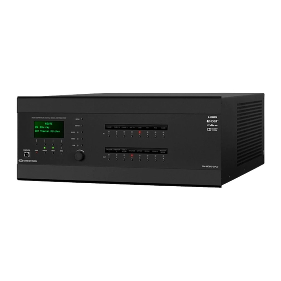
Physical Description The following sections provide information about the front and rear views of the DM-MD8X8-CPU3, DM-MD16X16-CPU3, and DM-MD32X32-CPU3 and related redundant power supply models (DM-MD8X8-CPU3-RPS, DM-MD16X16-CPU3-RPS, and DM-MD32X32-CPU3-RPS). Front View This section provides information about the connectors, controls, and indicators on the front of the DM-MD8X8-CPU3, DM-MD16X16-CPU3, and DM-MD32X32-CPU3 and related RPS models. - Page 7 DM-MD8X8-CPU3-RPS Front View DM-MD8X8-CPU3-RPS Product Manual – DOC. 8418A DigitalMedia Switchers • 3...
- Page 8 DM-MD16X16-CPU3 Front View DM-MD16X16-CPU3 4 • DigitalMedia Switchers Product Manual – DOC. 8418A...
- Page 9 DM-MD16X16-CPU3-RPS Front View DM-MD16X16-CPU3-RPS Product Manual – DOC. 8418A DigitalMedia Switchers • 5...
- Page 10 DM-MD32X32-CPU3 Front View DM-MD32X32-CPU3 6 • DigitalMedia Switchers Product Manual – DOC. 8418A...
- Page 11 DM-MD32X32-CPU3-RPS Front View DM-MD32X32-CPU3-RPS Product Manual – DOC. 8418A DigitalMedia Switchers • 7...
- Page 12 LCD Display: Green LCD dot matrix, 128 x 64 resolution adjustable LED backlight, displays inputs and outputs by name, video and audio signal information, and Ethernet configuration and setup menus Soft Buttons: Push buttons for activation of LCD-driven functions ...
-
Page 13: Rear View
Rear View This section provides information about the connectors, controls, and indicators on the rear of the DM-MD8X8-CPU3, DM-MD16X16-CPU3, and DM-MD32X32-CPU3 and related redundant power supply models (DM-MD8X8-CPU3-RPS, DM-MD16X16-CPU3-RPS, and DM-MD32X32-CPU3-RPS). DM-MD8X8-CPU3 and DM-MD8X8-CPU3-RPS Rear View ... - Page 14 DM-MD32X32-CPU3 and DM-MD32X32-CPU3-RPS Rear View 10 • DigitalMedia Switchers Product Manual – DOC. 8418A...
-
Page 15: Using The Web Interface
Access the Web Interface To access the web interface: Using the Device Discovery Tool in the Crestron Toolbox™ software, find the IP address of the switcher. 2. Open a web browser, and then go to the IP address of the switcher. - Page 16 Sample Adobe Flash Player Enable Page and Dialog Box When Adobe Flash Player is allowed to run, a Crestron splash screen appears, indicating that the web interface is loading. 12 • DigitalMedia Switchers Product Manual – DOC. 8418A...
-
Page 17: Navigate The Web Interface
Crestron Splash Screen When the web interface is accessed for the first time, the Ethernet Setup page opens. NOTE: After the initial Ethernet Setup settings have been accepted or the settings have been changed and applied for the first time, the Main page opens when the web interface is accessed. - Page 18 • Inputs page NOTE: As indicated on the Inputs page, configuration of input cards must be performed using DMTool in the Crestron Toolbox software. • Outputs page NOTE: As indicated on the Outputs page, configuration of output cards must be performed using DMTool in the Crestron Toolbox software.
-
Page 19: View Or Configure Ethernet Settings
View or Configure Ethernet Settings View or configure Ethernet settings and control system information on the Ethernet Setup page. The page also enables connection of the switcher to the Crestron XiO Cloud™ service, backward compatibility between a CPU3 and CPU card, content LAN mode, and SSL (Secure Sockets Layer). -
Page 20: View Ethernet Setup Settings
Sample Ethernet Setup Page View Ethernet Setup Settings The Current Status section of the Ethernet Setup page displays the following settings: • DHCP: Indicates whether DHCP (Dynamic Host Configuration Protocol) is ON or OFF. • Link State: Indicates whether an Ethernet link is established between the switcher and the network: A green circle and the word Up indicate that the switcher is connected to the network. -
Page 21: Configure Ethernet Setup Settings
• • The System ID of the switcher is set to 1. • Connection to the Crestron XiO Cloud service is set to Enable. DMC-CPU Compatibility Mode and Content LAN Mode are disabled. • • SSL Certificate is set to Off. - Page 22 6. Click the Apply Settings & Reboot button to save the settings and reboot the system. Configure Control System Connection Settings Configure control system connection settings in the Control System Connection section of the Ethernet Setup page: Enter the unique IP address or hostname of the control system. 2.
- Page 23 Configure Crestron XiO Cloud Service Connection By default, connection of the switcher to the Crestron XiO Cloud service is enabled. To enable or disable the service: On the Ethernet Setup page, click the XiO Cloud button. The Crestron XiO Cloud Service Setting page opens.
- Page 24 3. In order for the new setting to take effect, click YES to reboot the switcher. A message appears indicating that the system is rebooting. Configure DMC-CPU Compatibility Mode DMC-CPU compatibility mode provides backward compatibility between the DMC-CPU3 card and the DMC-CPU card without the need for additional programming. DMC-CPU compatibility mode must be enabled when either of the following occurs: •...
- Page 25 Configure Content LAN Mode Content LAN mode controls whether the CONTENT port of the DMC-CPU3 card in the switcher will be used to provide a dedicated LAN connection for streaming content to and from DMC streaming input and output cards (DMC-STR and DMC-STRO, respectively).
- Page 26 Enable SSL An SSL (Secure Sockets Layer) certificate provides secure, encrypted communications (HTTPS) between a website and a web browser. SSL is enabled by default (set to Off). To enable SSL: Select one of the following buttons: • Self: Generates a self-signed certificate, which provides data encryption •...
-
Page 27: Route Inputs To Outputs
Route Inputs to Outputs An input can be routed to one or more outputs. In addition, audio and USB breakaway routes can be configured. To route an input to one or more outputs: On the Selection Menu page, click the Main icon. Selection Menu Page –... - Page 28 Main Page – Default View (DM-MD8X8-CPU3 Page Shown) By default, the Main page can display up to 16 inputs and outputs at a time as applicable to a switcher. Input and output numbers, which correspond to the inputs and outputs on the rear of the switcher, are displayed. Input and output names are also displayed.
- Page 29 Main Page – Alternate View (DM-MD8X8-CPU3 Page Shown) In the alternate view, up to 32 inputs and outputs can be displayed at one time as applicable to a switcher. Only the input and output numbers are displayed. The input and output names are not displayed. In addition, inputs and outputs that are installed in the chassis but are not connected to source and display devices, respectively, are shaded white.
- Page 30 4. On the Inputs section of the page, select the desired input to be routed and observe the following: • A blue border highlights the selected input. • The input name, video resolution, refresh rate, and audio format are indicated at the top of the screen.
-
Page 31: Set Or Edit A Password
Set or Edit a Password By default, a password is not required to access the web interface. Set or edit a password to control access to the web interface. To set or edit a password: On the Selection Menu page, click the Password icon. Selection Menu Page –... - Page 32 Password Setup Page 2. Do either of the following: • If a password is to be used to access all pages except the Main page, click the Setup Only button. A lock appears next to the menu icon ( ) on the Main page indicating that access to all other pages requires the use of a password.
-
Page 33: Edit Input And Output Names
System Is Locked Dialog Box 6. In the Password text box, enter the password and then click Enter. The Selection Menu page opens. Edit Input and Output Names Default names are assigned to the inputs and outputs based on input and output numbers. - Page 34 Selection Menu Page – Naming Icon The Naming page opens, allowing input names to be edited. 30 • DigitalMedia Switchers Product Manual – DOC. 8418A...
- Page 35 Naming Page – Edit Input Names (DM-MD8X8-CPU3 Page Shown) To edit input names: If the Naming – Edit Input Names page is not shown, click the Inputs button (default selection). 2. For each input name to be edited: a. Click the input name. On the right side of the page, the Current Number text box (read only) displays the number of the input, and the Current Name text box (read only) displays the current name of the input.
- Page 36 To edit output names: On the Naming page, click the Outputs button. The Naming – Edit Output Names page opens. Naming Page – Edit Output Names (DM-MD8X8-CPU3 Page Shown) 2. For each desired output name to be edited: a. Click the output name. On the right side of the page, the Current Number text box (read only) displays the number of the output, and the Current Name text box (read only) displays the current name of the output.
-
Page 37: View Or Update Firmware Versions
View or Update Firmware Versions View or update firmware versions of the DigitalMedia system components (for example, DMC cards) on the Firmware Setup page. To access the Firmware Setup page: On the Selection Menu page, click the Firmware icon. Selection Menu Page – Firmware Icon The Firmware Setup page opens. -
Page 38: View Versions Of System Components
Firmware Setup Page View Versions of System Components To view the firmware versions of the DigitalMedia system components: On the Firmware Setup page, click the Check Versions button. A list of DigitalMedia system components and corresponding information appears, including the current firmware version of each component (CUR VER) and the firmware version of the Package Update File (PUF VER) that is loaded. - Page 39 Sample Firmware Setup Page – Check Versions To view the entire contents of the page, use the up ( ) and down ( ) buttons on the right side of the page. Product Manual – DOC. 8418A DigitalMedia Switchers • 35...
-
Page 40: View Last Firmware Updates
View Last Firmware Updates To view the last firmware updates: On the Firmware Setup page, click the View Last Update button. Sample Firmware Setup Page – View Last Update A list of DigitaMedia system components that were last updated appears and indicates the status of the updates (Success or Failure). -
Page 41: Update Firmware Manually
To update firmware using an FTP client: If a USB flash drive is inserted into the USB port on the DMC-CPU3 card, remove the flash drive. 2. Download the latest firmware file from the Crestron website to a computer. x.xx.xx x.xx.xx The firmware file is named digitalmedia_ .puf (... - Page 42 Insert a USB flash drive into the USB port of a computer. 2. Download the latest firmware file from the Crestron website to the root directory on the flash drive—do not download the file to a subfolder on the flash x.xx.xx...
-
Page 43: Update Firmware Automatically
To view the entire contents of the page, use the up ( ) and down ( ) buttons on the right side of the page. Update Firmware Automatically Automatic firmware update can be enabled or disabled. To update firmware automatically: On the Firmware Setup page, click the Auto Update button. - Page 44 URL not be changed. • Device User Name and Password: Enter the user name and password of the switcher if authentication was enabled in the Crestron Toolbox software. • Server User Name and Password: Enter the user name and password of the server that stores the PUF and manifest files for the switcher.
- Page 45 Configure Auto Update Settings To configure Auto Update settings: On the Auto Update page, click the Settings button at the bottom of the page. The Auto Update Settings page opens. By default, Use Poll Interval is selected. Auto Update Settings – Use Poll Interval Page 2.
- Page 46 5. Check the status of the update. Refer to “Check Update Status” on page 43 for instructions. Set Day and Time To set a specific day and time to update the firmware: On the Auto Update Settings page, select the Set Day & Time button. The Auto Update Settings - Set Day &...
- Page 47 Check Update Status To check the status of the automatic update process, click the Check Now button on the Auto Update page. Auto Update Page – Update Status The Update Status section indicates the status as any of the following: •...
-
Page 48: Reboot The System
Reboot the System To reboot the system: On the Selection Menu page, click the System icon. Selection Menu Page – System Icon The System page opens. 44 • DigitalMedia Switchers Product Manual – DOC. 8418A... - Page 49 System Page 2. Click the Reboot button. A dialog box appears asking for confirmation that the system be rebooted. Reboot Confirmation Dialog Box 3. Click YES. A message appears indicating that the system is rebooting. Product Manual – DOC. 8418A DigitalMedia Switchers •...
-
Page 50: Restore Factory Default Settings
Restore Factory Default Settings To restore factory default settings: On the Selection Menu page, click the System icon. Selection Menu Page – System Icon The System page opens. 46 • DigitalMedia Switchers Product Manual – DOC. 8418A... - Page 51 System Page 2. Click the Restore button. A dialog box appears asking for confirmation that the factory default settings be restored. Restore Confirmation Dialog Box 3. Click YES. A message appears indicating that the system is rebooting. Product Manual – DOC. 8418A DigitalMedia Switchers •...
-
Page 52: View The Error Log
View the Error Log For troubleshooting purposes, view the error log. To view the error log: On the Selection Menu page, click the Error Log icon. Selection Menu Page – Error Log The error log appears. 48 • DigitalMedia Switchers Product Manual –... - Page 53 Sample Error Log If necessary, use the up ( ) and down ( ) buttons to view the entire contents of the error log. To clear the error log, click the Clear Errors button at the top of the page. Product Manual –...
-
Page 54: Using The Front Panel Lcd
Using the Front Panel LCD The front panel LCD provides the Installer Tools menu, which consists of the following menu items: • Inputs • Outputs • Network Setup • Control Setup Access the Installer Tools Menu To access the Installer Tools menu: Press the MENU button. -
Page 55: Navigate The Installer Tools Menu
Navigate the Installer Tools Menu To navigate the Installer Tools menu: To navigate upward or downward in a menu, use the selection knob. • • To move the cursor to the right when entering data, press the > soft button. •... -
Page 56: Viewing Routing Information
4. If desired, deselect the outputs to which the input is currently routed by pressing the corresponding OUT buttons. The LEDs of the corresponding outputs go off. 5. Press the appropriate OUT buttons that correspond to the desired outputs. The LEDs of the selected outputs light. 6. -
Page 57: Viewing Signal Information
Viewing Signal Information Information about input and output signals can be viewed on the LCD. Depending on the input selected, information such as the name of the input, the detected resolution, the detected video type, the detected frame rate, the detected aspect ratio, the HDCP state, and the deep color setting can be viewed. -
Page 58: Appendix: Dmc Series Cards
Appendix: DMC Series Cards DMC Series cards for the DM-MD8X8-CPU3, DM-MD16X16-CPU3, and DM-MD32X32-CPU3 and related redundant power supply models consist of the following: • DMC-CPU3 card (see below) • Input cards (refer to page 55) • Output cards (refer to page 71) DMC-CPU3 Card The DMC-CPU3 card is based on the 3-Series®... -
Page 59: Dmc Input Cards
USB 2.0 host port for connection of a USB flash drive; For saving/loading EDID settings and for firmware update For additional information, visit the DMC-CPU3 product page on the Crestron website. DMC Input Cards DMC input cards include the following: •... -
Page 60: Dmc-4Kz-C Input Card
Compatible with PoE+, PoDM+, and PoDM++ AUDIO OUT L, R: RCA connectors, female; Unbalanced stereo line level audio output For additional information, visit the DMC-4KZ-C product page on the Crestron website. 56 • DigitalMedia Switchers Product Manual – DOC. 8418A... -
Page 61: Dmc-4Kz-C-Dsp Input Card
Compatible with PoE+, PoDM+, and PoDM++ AUDIO OUT L, R: RCA connectors, female; Unbalanced stereo line level audio output For additional information, visit the DMC-4KZ-C-DSP product page on the Crestron website. Product Manual – DOC. 8418A DigitalMedia Switchers • 57... -
Page 62: Dmc-4Kz-Hd Input Card
USB device port for connection to the USB host interface of a computer or other USB HID compliant host AUDIO OUT L, R: RCA connectors, female; Unbalanced stereo line level audio output For additional information, visit the DMC-4KZ-HD product page on the Crestron website. 58 • DigitalMedia Switchers Product Manual – DOC. 8418A... -
Page 63: Dmc-4Kz-Hd-Dsp Input Card
USB device port for connection to the USB host interface of a computer or other USB HID compliant host AUDIO OUT L, R: RCA connectors, female; Unbalanced stereo line level audio output For additional information, visit the DMC-4KZ-HD-DSP product page on the Crestron website. Product Manual – DOC. 8418A DigitalMedia Switchers • 59... -
Page 64: Dmc-Dvi Input Card
USB HID compliant host AUDIO IN L, R: 5-pin 3.5 mm detachable terminal block; Balanced/unbalanced stereo line level audio input For additional information, visit the DMC-DVI product page on the Crestron website. 60 • DigitalMedia Switchers Product Manual – DOC. 8418A... -
Page 65: Dmc-S Input Card
DM IN MMF/SC LED: Green LED, indicates DM link status AUDIO OUT L, R: RCA connectors, female; Unbalanced stereo line level audio output For additional information, visit the DMC-S product page on the Crestron website. Product Manual – DOC. 8418A DigitalMedia Switchers • 61... -
Page 66: Dmc-S-Dsp Input Card
DM IN MMF/SC LED: Green LED, indicates DM link status AUDIO OUT L, R: RCA connectors, female; Unbalanced stereo line level audio output For additional information, visit the DMC-S-DSP product page on the Crestron website. 62 • DigitalMedia Switchers Product Manual – DOC. 8418A... -
Page 67: Dmc-S2 Input Card
DM IN SMF/LC LED: Green LED, indicates DM link status AUDIO OUT L, R: RCA connectors, female; Unbalanced stereo line level audio output For additional information, visit the DMC-S2 product page on the Crestron website. Product Manual – DOC. 8418A DigitalMedia Switchers • 63... -
Page 68: Dmc-S2-Dsp Input Card
DM IN SMF/LC LED: Green LED, indicates DM link status AUDIO OUT L, R: RCA connectors, female; Unbalanced stereo line level audio output For additional information, visit the DMC-S2-DSP product page on the Crestron website. 64 • DigitalMedia Switchers Product Manual – DOC. 8418A... -
Page 69: Dmc-Sdi Input Card
SDI video/audio loop-through output AUDIO OUT L, R: RCA connectors, female; Unbalanced stereo line level audio output For additional information, visit the DMC-SDI product page on the Crestron website. Product Manual – DOC. 8418A DigitalMedia Switchers • 65... -
Page 70: Dmc-Str Input Card
Amber LED indicates Ethernet activity AUDIO OUT L, R: RCA connectors, female; Unbalanced stereo line level audio output For additional information, visit the DMC-STR product page on the Crestron website. 66 • DigitalMedia Switchers Product Manual – DOC. 8418A... -
Page 71: Dmc-Vga Input Card
USB HID compliant host AUDIO IN L, R: 5-pin 3.5 mm detachable terminal block; Balanced/unbalanced stereo line level audio input For additional information, visit the DMC-VGA product page on the Crestron website. Product Manual – DOC. 8418A DigitalMedia Switchers • 67... -
Page 72: Dmc-Vid4 Input Card
Composite video inputs For additional information, visit the DMC-VID4 product page on the Crestron website. DMC-VID-BNC Input Card The DMC-VID-BNC is an input card that provides a multi-format BNC analog video input for the connection of component, S-Video, and composite video sources. An HDMI output and balanced/unbalanced analog audio input are also included. -
Page 73: Dmc-Vid-Rca-A Input Card
Signal Types: Component (YPbPr), S-Video (Y/C), or composite IN - AUDIO IN L, R: 2 RCA female connectors; Unbalanced stereo line level audio input For additional information, refer to the DMC-VID-RCA-A product page on the Crestron website. Product Manual – DOC. 8418A DigitalMedia Switchers • 69... -
Page 74: Dmc-Vid-Rca-D Input Card
Signal Types: Component (YPbPr), S-Video (Y/C), or composite IN - SPDIF: RCA female; S/PDIF coaxial digital audio input For additional information, refer to the DMC-VID-RCA-D product page on the Crestron website. 70 • DigitalMedia Switchers Product Manual – DOC. 8418A... -
Page 75: Dmc Output Cards
HDMI digital video/audio outputs (DVI compatible) L, R: 5-pin 3.5 mm detachable terminal blocks; Balanced/unbalanced stereo line level audio outputs For additional information, refer to the DMC-4KZ-HDO product page on the Crestron website. Product Manual – DOC. 8418A DigitalMedia Switchers • 71... -
Page 76: Dmc-4Kz-Co-Hd Output Card
HDMI: HDMI Type A connector, female; HDMI digital video/audio output (DVI compatible); Outputs same signal as the first DM OUT port For additional information, refer to the DMC-4KZ-CO-HD product page on the Crestron website. 72 • DigitalMedia Switchers Product Manual – DOC. 8418A... -
Page 77: Dmc-Hdo Output Card
Balanced/unbalanced stereo line level audio outputs For additional information, refer to the DMC-HDO product page on the Crestron website. DMC-S2O-HD Output Card The DMC-S2O-HD is a 2-channel DigitalMedia 8G single-mode fiber output card. An HDMI output is also provided. -
Page 78: Dmc-So-Hd Output Card
HDMI digital video/audio output (DVI compatible); Outputs same signal as the first MMF/SC output For additional information, refer to the DMC-SO-HD product page on the Crestron website. DMC-STRO Output Card The DMC-STRO is an H.264 streaming output card. DMC-STRO Card ... - Page 79 This page is intentionally left blank. Product Manual – DOC. 8418A DigitalMedia Switchers • 75...
- Page 80 Crestron Electronics, Inc. Product Manual – DOC. 8418A 15 Volvo Drive, Rockleigh, NJ 07647 (2053018) Tel: 888.CRESTRON 12/31/19 Fax: 201.767.7576 Specifications subject to www.crestron.com change without notice.
Need help?
Do you have a question about the DigitalMedia DM-MD8X8-CPU3 and is the answer not in the manual?
Questions and answers