Crestron DigitalMedia DM-MD64X64 Supplemental Manual
Hide thumbs
Also See for DigitalMedia DM-MD64X64:
- Operations & installation manual (84 pages) ,
- Quick start (5 pages) ,
- Quick start manual (2 pages)

Related Manuals for Crestron DigitalMedia DM-MD64X64


Summary of Contents for Crestron DigitalMedia DM-MD64X64
- Page 1 DM-MD64X64/DM-MD128X128 DigitalMedia™ Switchers Supplemental Guide Crestron Electronics, Inc.
- Page 2 HDMI Licensing LLC in the United States and/or other countries. Other trademarks, registered trademarks, and trade names may be used in this document to refer to either the entities claiming the marks and names or their products. Crestron disclaims any proprietary interest in the marks and names of others.
-
Page 3: Table Of Contents
Contents Introduction Physical Description DM-MD64X64 ....................... 2 Front View ....................... 2 Rear View ........................ 3 DM-MD128X128 ......................5 Front View ....................... 5 Rear View ........................ 6 Ethernet Setup Web Interface Overview Firmware Upgrade Using an FTP Client ..................... 10 Using a USB Flash Drive ....................11 Troubleshooting Appendix: DigitalMedia Blades CPU Blade ........................ -
Page 5: Introduction
In addition, information about each of the DigitalMedia blades is provided in the appendix of this manual. For information about installing the DigitalMedia switchers, refer to the DM-MD64X64/DM-MD128X128 DO Guide (Doc. 7328) at www.crestron.com/manuals. DM-MD64X64/DM-MD128X128: DigitalMedia Switchers • 1 Supplemental Guide – DOC. 7318F... -
Page 6: Physical Description
Physical Description The following sections provide information about the connectors, controls, and indicators on the front and rear of the DM-MD64X64 and DM-MD128X128. DM-MD64X64 This section provides information about the connectors, controls, and indicators that are available on the front and rear of the DM-MD64X64. Front View The following illustration shows the front of the DM-MD64X64. -
Page 7: Rear View
Power Supply FAULT LED: Red flashing LED, indicates a fault with a power supply NOTE: Although the DM-MD64X64 continues to operate if a single power supply fails, it is recommended that the failed power supply be replaced as soon as possible to restore power supply redundancy. - Page 8 CPU Slot: Accepts one DMB-4K-CPU-64 blade (included, refer to page 14 for information about the CPU blade) Fan Tray: Hot-swappable, Crestron model DM-MDA-64-FANTRAY (included) 100–127V ~ 50/60Hz 16A, 200-240V ~ 50/60Hz 8A: Two IEC 60320 C-20 mains ...
-
Page 9: Dm-Md128X128
DM-MD128X128 This section provides information about the connectors, controls, and indicators that are available on the front and rear of the DM-MD128X128. Front View The following illustration shows the front of the DM-MD128X128. DM-MD128X128 Front View ... -
Page 10: Rear View
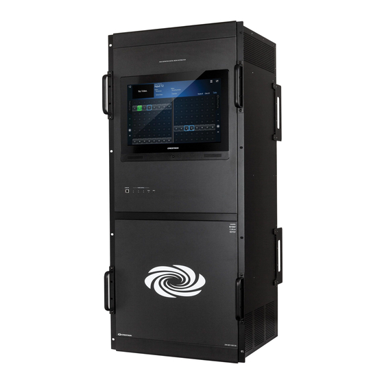
Touch Screen: 15 inch (381 mm) diagonal TFT active matrix color LCD, 15:9 WXGA, 1280 x 768 pixels, resistive touch membrane, amplified speakers; Provides signal routing, video input preview, video and audio signal information, system diagnostics, setup and configuration Touch Screen Hard Key: Not used ... - Page 11 DM-MD128X128 Rear View DM-MD64X64/DM-MD128X128: DigitalMedia Switchers • 7 Supplemental Guide – DOC. 7318F...
- Page 12 CPU Slot: Accepts one DMB-4K-CPU-128 blade (included, refer to page 14 for information about the CPU blade). Fan Tray: Hot-swappable, Crestron model DM-MDA-128-FANTRAY (included) 100–127V ~ 50/60Hz 16A, 200–240V ~ 50/60Hz 8A: Three IEC 60320 C-20 mains ...
-
Page 13: Ethernet Setup
DM switchers in the same system must be unique. When setting the IP ID, consider the following: • The IP ID of each unit must match an IP ID specified in the Crestron Studio ® SIMPL Windows program. •... -
Page 14: Web Interface Overview
To upgrade firmware using an FTP client on a computer, do the following: 1. If a USB flash drive is inserted into the USB port on the CPU blade, remove the USB flash drive. 2. Download the latest firmware file from the Crestron website to the PC. The firmware X.XXX.XXXX X.XXX.XXXX file is named dm-md64x64_dm-md128x128_ .zip (... -
Page 15: Using A Usb Flash Drive
1. Insert a USB flash drive into the USB port on a PC. 2. Download the latest firmware file from the Crestron website to the flash drive—do not download the file to a subfolder on the flash drive. The firmware file is named X.XXX.XXXX... -
Page 16: Troubleshooting
Troubleshooting The following table provides troubleshooting information. If further assistance is required, contact a Crestron customer service representative. DM-MD64X64 and DM-MD128X128 Troubleshooting TROUBLE POSSIBLE CAUSE(S) CORRECTIVE ACTION The audio or video is The source does not match Check the EDID capabilities of the distorted. -
Page 17: Appendix: Digitalmedia Blades
Appendix: DigitalMedia Blades DigitalMedia blades for the DM-MD64X64 and DM-MD128X128 consist of the following: • CPU blade (refer to the following page) • Input blades (refer to page 17) • Output blades (refer to page 28) DM-MD64X64/DM-MD128X128: DigitalMedia Switchers • 13 Supplemental Guide –... -
Page 18: Cpu Blade
CPU Blade A CPU blade is included with the DM switchers. The DMB-4K-CPU-64 is the CPU blade for the DM-MD64X64, and the DMB-4K-CPU-128 is the CPU blade for the DM-MD128X128. The DMB-4K-CPU-64 and DMB-4K-CPU-128 enable video preview monitoring of 4K and Ultra HD sources and include a dedicated Dante ®... - Page 19 If required, the DANTE port can be repurposed as a Service port. To repurpose the DANTE port as a Service port, refer to Answer ID 5347 in the Online Help section of the Crestron website (www.crestron.com). USB: USB Type A female; USB 2.0 host port for connection of a USB flash drive;...
-
Page 20: Connections
Connections The following illustration provides information about connections to the DMB-4K-CPU-64 and DMB-4K-CPU-128 blades. Connect the CPU blade of the DigitalMedia switcher as required for the application. DMB-4K-CPU-64 and DMB-4K-CPU-128 Connections DMB-4K-CPU-64 DMB-4K-CPU-128 LAN: LAN: 10BASE-T/100BASE-TX/ 10BASE-T/100BASE-TX/ 1000BASE-T Ethernet 1000BASE-T Ethernet to LAN to LAN DANTE:... -
Page 21: Input Blades
Input Blades DMB series input blades include the following: • DMB-4K-I-C, 8-channel HDBaseT certified 4K DigitalMedia 8G+ input blade ® ® (refer to the following page) • DMB-4K-I-HD, 8-channel 4K HDMI input blade (refer to page 20) • DMB-4K-I-HD-DNT, 8-channel 4K HDMI and Dante input blade (refer to page 22) •... -
Page 22: Dmb-4K-I-C
DMB-4K-I-C The DMB-4K-I-C provides eight independent 4K DM 8G+ inputs, which are also ® compatible with the HDBaseT standard and are HDCP 2.2 compliant. The DMB-4K-I-C supports video resolutions up to 4K and Ultra HD and handles 3D video and Deep Color. The DMB-4K-I-C also supports Dolby TrueHD, Dolby Atmos , DTS HD... - Page 23 ACT LED: Green LED, indicates blade activity MSG LED: Red LED, indicates that an error message has been generated INPUT DM 1-8: 8-pin RJ-45 female with two LED indicators; DM 8G+ inputs, HDBaseT standard compliant; PoDM PSE port (HDBaseT PoE compatible); Green LED indicates DM link status;...
-
Page 24: Dmb-4K-I-Hd
DMB-4K-I-HD The DMB-4K-I-HD provides eight independent 4K HDMI inputs that are HDCP 2.2 compliant. The DMB-4K-I-HD supports video resolutions up to 4K and Ultra HD and handles 3D video and Deep Color. The DMB-4K-I-HD also supports Dolby TrueHD, Dolby Atmos, DTS HD, DTS:X, and uncompressed 7.1 linear PCM audio. Stereo analog audio inputs can also be enabled using the optional AUD-BOB-1602 analog audio breakout box (sold separately). - Page 25 ACT LED: Green LED, indicates blade activity MSG LED: Red LED, indicates that an error message has been generated INPUT HD 1-8 LEDs: Bicolor red/green LEDs, red indicates video lock and green indicates HDCP status for each corresponding input INPUT HD 1-8: 19-pin Type A HDMI female;...
-
Page 26: Dmb-4K-I-Hd-Dnt
DMB-4K-I-HD-DNT The DMB-4K-I-HD-DNT provides eight independent 4K HDMI inputs that are HDCP 2.2 compliant. The DMB-4K-I-HD-DNT supports video resolutions up to 4K and Ultra HD and handles 3D video and Deep Color. The DMB-4K-I-HD-DNT also supports Dolby TrueHD, Dolby Atmos, DTS HD, and uncompressed 7.1 linear PCM audio. The DMB-4K-I-DNT also supports Dante audio networking, which allows for interfacing with other Dante enabled equipment over the local area network to send and receive streaming stereo audio on any or all of the eight input channels. - Page 27 ACT LED: Green LED, indicates blade activity MSG LED: Red LED, indicates that an error message has been generated INPUT HD 1-8 LEDs: Bicolor red/green LEDs, red indicates video lock and green indicates HDCP status for each corresponding input INPUT HD 1-8: 19-pin Type A HDMI female;...
-
Page 28: Dmb-I-S
DMB-I-S The DMB-I-S provides eight independent DM 8G multimode fiber inputs that are HDCP ® compliant. The DMB-I-S handles video resolutions up to Full HD 1080p, computer resolutions up to WUXGA, and 3D video and Deep Color. Dolby TrueHD, DTS HD, and uncompressed 7.1 linear PCM audio signals are also supported. - Page 29 ACT LED: Green LED, indicates blade activity MSG LED: Red LED, indicates that an error message has been generated INPUT MMF/SC 1-8 LEDs: Green LEDs, indicate DM link status for each corresponding input INPUT MMF/SC 1-8: SC female optical fiber connectors; ...
-
Page 30: Dmb-I-S2
DMB-I-S2 The DMB-I-S2 provides eight independent DM 8G single-mode fiber inputs that are HDCP compliant. The DMB-I-S2 handles video resolutions up to Full HD 1080p, computer resolutions up to WUXGA, and 3D video and Deep Color. Dolby TrueHD, DTS HD, and uncompressed 7.1 linear PCM audio signals are also supported. - Page 31 ACT LED: Green LED, indicates blade activity MSG LED: Red LED, indicates that an error message has been generated INPUT SMF/LC 1-8 LEDs: Green LEDs, indicate DM link status for each corresponding input INPUT SMF/LC 1-8: LC female optical fiber connectors; ...
-
Page 32: Output Blades
Output Blades DMB series output blades include the following: • DMB-4K-O-C, 8-channel HDBaseT certified 4K DigitalMedia 8G+ output blade (refer to the following page) • DMB-4K-O-HD, 8-channel 4K scaling HDMI output blade (refer to page 29) • DMB-4K-O-HD-DNT, 8-channel 4K HDMI and Dante output blade (refer to page 33) •... -
Page 33: Dmb-4K-O-C
DMB-4K-O-C The DMB-4K-O-C provides eight independent 4K DM 8G+ outputs, which are also compatible with the HDBaseT standard and are HDCP 2.2 compliant. The DMB-4K-O-C supports video resolutions up to 4K and Ultra HD and handles 3D video and Deep Color. Dolby TrueHD, Dolby Atmos, DTS HD, and uncompressed 7.1 linear PCM audio is also supported. - Page 34 Connections The following illustration provides information about connections to the DMB-4K-O-C. Connect the blade as required for the application. DMB-4K-O-C Connections OUTPUT DM 1-8: To DM 8G+ input of DM receivers or other DM devices or to HDBaseT devices PoDM INPUT PWR: From PoDM or HDBaseT PoE power source...
-
Page 35: Dmb-4K-O-Hd
DMB-4K-O-HD The DMB-4K-O-HD provides eight independent 4K HDMI outputs that are HDCP 2.2 compliant. Each output also provides a 4K/60 scaler. The scaler can upscale video and computer sources to match the native resolution of any screen up to Ultra HD and 4K, and can also downscale 4K, UHD and ultra-high-resolution computer signals to enable viewing on 1080p and lower resolution displays. - Page 36 ACT LED: Green LED, indicates blade activity MSG LED: Red LED, indicates that an error message has been generated OUTPUT HD 1-8 LEDs: Bicolor red/green LEDs, red indicates video lock and green indicates HDCP status for each corresponding output OUTPUT HD 1-8: 19-pin Type A HDMI female;...
-
Page 37: Dmb-4K-O-Hd-Dnt
DMB-4K-O-HD-DNT The DMB-4K-O-HD-DNT provides eight independent 4K HDMI outputs that are HDCP 2.2 compliant. Each output also provides a 4K/60 scaler. The scaler can upscale video and computer sources to match the native resolution of any screen up to Ultra HD and 4K, and can also downscale 4K, UHD and ultra high resolution computer signals to enable viewing on 1080p and lower resolution displays. - Page 38 ACT LED: Green LED, indicates blade activity MSG LED: Red LED, indicates that an error message has been generated OUTPUT HD 1-8 LEDs: Bicolor red/green LEDs, red indicates video lock and green indicates HDCP status for each corresponding output OUTPUT HD 1-8: 19-pin Type A HDMI female;...
-
Page 39: Dmb-O-S
DMB-O-S The DMB-O-S provides eight independent DM 8G multimode fiber outputs that are HDCP compliant. The DMB-O-S handles video resolutions up to Full HD 1080p, computer resolutions up to WUXGA, and 3D video and Deep Color. Dolby TrueHD, DTS HD, and uncompressed 7.1 linear PCM audio signals are also supported. - Page 40 ACT LED: Green LED, indicates blade activity MSG LED: Red LED, indicates that an error message has been generated OUTPUT MMF/SC 1-8 LEDs: Green LEDs, indicate DM link status for each corresponding output OUTPUT MMF/SC 1-8: SC female optical fiber connectors; ...
-
Page 41: Dmb-O-S2
DMB-O-S2 The DMB-O-S2 provides eight DM 8G single-mode fiber outputs that are HDCP compliant. The DMB-O-S2 handles video resolutions up to Full HD 1080p, computer resolutions up to WUXGA, and 3D video and Deep Color. Dolby TrueHD, DTS HD, and uncompressed 7.1 linear PCM audio signals are also supported. - Page 42 ACT LED: Green LED, indicates blade activity MSG LED: Red LED, indicates that an error message has been generated OUTPUT SMF/LC 1-8 LEDs: Green LEDs, indicate DM link status for each corresponding output OUTPUT SMF/LC 1-8: LC female optical fiber connectors; ...
- Page 43 This page is intentionally left blank. DM-MD64X64/DM-MD128X128: DigitalMedia Switchers • 39 Supplemental Guide – DOC. 7318F...
- Page 44 Crestron Electronics, Inc. Supplemental Guide – DOC. 7318F 15 Volvo Drive, Rockleigh, NJ 07647 (2035906) Tel: 888.CRESTRON 01.18 Fax: 201.767.7576 Specifications subject to www.crestron.com change without notice.
Need help?
Do you have a question about the DigitalMedia DM-MD64X64 and is the answer not in the manual?
Questions and answers