
Related Manuals for Kramer WP-501


Summary of Contents for Kramer WP-501
-
Page 1: User Manual
K R A ME R E LE CT R O N IC S L T D . USER MANUAL MODEL: WP-501 Wall Plate Solution for Simple Room Control and Signal Switching P/N: 2900-000753 Rev 1... -
Page 2: Table Of Contents
F igure 1: WP-501 Front Panel F igure 2: WP-501 Rear Panel F igure 3: Grounding Connection Components F igure 4: The Setup Internal Panel F igure 5: Connecting the WP-501 Front Panel F igure 6: Connecting the WP-501 Rear Panel WP-501 – Contents... -
Page 3: Introduction
GROUP 9: Room Connectivity; GROUP 10: Accessories and Rack Adapters; GROUP 11: Sierra Products Congratulations on purchasing your Kramer WP-501 Wall Plate Solution for Simple Room Control and Signal Switching that can be used as a projector switcher and controller in the classroom. -
Page 4: Getting Started
Getting Started This user manual is written for the end user. Refer to the separate Kramer K-Config Guide (available online) for details of how to install and configure the Room Controller. We recommend that you: • Unpack the equipment carefully and save the original box and packaging materials for possible future shipment •... -
Page 5: Overview
Ethernet port Kramer Site-CTRL is a powerful A/V asset management tool. It offers real-time network monitoring and control of Kramer Master controllers installed at an A/V site and all the connected A/V equipment. The Kramer Site-CTRL downloadable version can monitor and control up to 100 Kramer Master controllers. -
Page 6: Defining The Wp-501
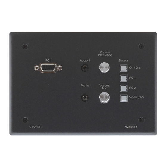
Defining the WP-501 This section defines the WP-501. Figure 1: WP-501 Front Panel Feature Function VOLUME MIC Adjustment Rotate clockwise to increase the microphone level Knob MIC IN 3.5mm mini jack Connect to microphone PC 1 15-Pin HD Connector Connect to the PC 1 source (pins ED12 and ED15 pass the EDID informa ion) AUDIO 1 3.5mm mini jack... -
Page 7: F Igure 2: Wp-501 Rear Panel
Connect to the PC 2 source (pins ED12 and ED15 pass the EDID information) Make sure you use 15-wire VGA cables between the WP-501 and the PC2 to enable EDID communication AUDIO IN 2 Terminal Connect to the unbalanced stereo audio signal of the PC2... -
Page 8: Grounding The Wp-501
2. Insert the M3x6 screw through the toothed lock washers and the tongue terminal in the order shown above. 3. Insert the M3x6 screw (with the two toothed lock washers and ring tongue terminal) into the grounding screw hole and tighten the screw. WP-501 - Defining the WP-501... -
Page 9: Using Your Wp-501
Using Your WP-501 This user manual is applicable once the unit is installed and configured by authorized Kramer technical personnel or by an external system integrator. The installation process is not detailed in this user manual, and includes configuration via the Kramer K-Config Windows®-based configuration software. -
Page 10: Set The Wp-501
Set the WP-501 Before installing the front panel and mounting it on the wall, you need to setup the WP-501. This section defines the relevant internal panel components, viewed from the front panel side: Program Switch USB for Configuration Program... -
Page 11: Connecting The Wp-501
Connecting the WP-501 To connect the WP-501, as illustrated in the example in Figure 5 (front panel) and Figure 6 (rear panel), do the following: 1. On the front panel, connect: A computer graphics source and the audio source of the computer to the PC 1 15-pin HD and 3.5mm mini jack, respectively... -
Page 12: F Igure 6: Connecting The Wp-501 Rear Panel
4. Connect the relay terminal block connectors to the screen. 5. Connect the ETHERNET port to a PC for configuration and control (not shown in Figure 6), see Section 5.3 Figure 6: Connecting the WP-501 Rear Panel WP-501 - Using Your WP-501... -
Page 13: Operating The Wp-501
The Ethernet and/or USB ports are used by the technical installer to configure the WP-501 front panel SELECT buttons to set a sequence of actions in a trigger (a macro) and assign them to any of the buttons, such as those defined in the following example. -
Page 14: Technical Specifications
WEIGHT: 0.25 kg (0.55lbs) approx. ACCESSORIES: 12V DC, 0.5A power supply, screwdriver OPTIONS: USB cable 3' (0.91m) (Part number C-UA/MUB-3), WP-501 Installation cable, Site-CTRL™ Management Tool Software Specifications are subject to change without notice at http://www.kramerelectronics.com WP-501 - Technical Specifications... - Page 15 1. Any product which is not distributed by us or which is not purchased from an authorized Kramer dealer. If you are uncertain as to whether a dealer is authorized, please contact Kramer at one of the agents listed in the Web site www.kramerelectronics.com.
- Page 16 For the latest information on our products and a list of Kramer distributors, visit our Web site where updates to this user manual may be found. We welcome your questions, comments, and feedback. Web site: www.kramerelectronics.com E-mail: info@kramerel.com SAFETY WARNING...
Need help?
Do you have a question about the WP-501 and is the answer not in the manual?
Questions and answers