Sign In
Upload
Download
Table of Contents
Contents
Add to my manuals
Delete from my manuals
Share
URL of this page:
HTML Link:
Bookmark this page
Add
Manual will be automatically added to "My Manuals"
Print this page
×
Bookmark added
×
Added to my manuals
Manuals
Brands
Kramer Manuals
Switch
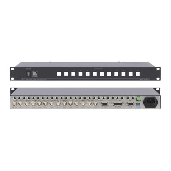
VS-1211
User manual
Kramer VS-1211 User Manual
Vertical interval switchers with balanced audio/ with unbalanced audio
Hide thumbs
1
Table Of Contents
2
3
4
5
6
7
8
9
10
11
12
13
14
15
16
17
18
19
20
21
22
23
24
25
page
of
25
Go
/
25
Contents
Table of Contents
Troubleshooting
Bookmarks
Table of Contents
User Manual
Table of Contents
Kramer Electronics Ltd
Location of Internal Jumpers
Introduction
A Word on Video/Audio Switchers
Factors Affecting Quality of Results
Specifications
How Do I Get Started
Unpacking and Contents
Optional Accessories
Kramer "Vs" Series Switchers
RS-232 Control Connector Wiring
Getting to Know Your Switcher
Table
Connecting to Audio Devices
Connecting to the VS-1211
Connecting to the VS-1201Xl
Connecting to Video Devices
Connecting to the VS-1211/1201Xl/1001Xlm
Dip Switches, Jumpers and Trimmers
DIP Switches
Jumpers, Their Uses and Set-Up Requirements
DIP Switch Settings
The Internal Trimmers
Controlling the Switcher
The VS-2000 System
The VS-1N/VS-1P System
Installation
Rackmounting
Additional Software Options
Powering on the Switcher
Using the Switcher
Operating an Individual Switcher
Selecting an Input on the Switchers
Selecting the Proper Sync Format
Using the VS-2000
Using the PC Control Software
Adding Outputs
Adding Inputs
Video Component and YC Switching
Controlling Several Independent Switchers Via a Single PC Port
Taking Care of Your Switcher
Troubleshooting
Power and Indicators
Video Signal
Audio Signal
Software
Control
Switching Malfunctions
Vertical Interval
PROTOCOL USED for VS-1211 1201Xl COMMUNICATION
Limited Warranty
Changing Communication Protocols
Connecting to a Pc
New Protocol 2000
Advertisement
Quick Links
1
User Manual
2
Table of Contents
3
Rs-232 Control Connector Wiring
4
Connecting to Audio Devices
5
Dip Switch Settings
Download this manual
KRAMER ELECTRONICS, Ltd.
USER MANUAL
Vertical Interval Switchers
MODELS: VS-1211, VS-1011, VS-811, VS-611, VS-411
With Balanced Audio
VS-1201xl, VS-1001xlm, VS-801xlm, VS-601xlm, VS-401xlm
With Unbalanced Audio
IMPORTANT: Before proceeding, please read paragraph entitled
"Unpacking and Contents"
Table of
Contents
Previous
Page
Next
Page
1
2
3
4
5
Advertisement
Table of Contents
Need help?
Do you have a question about the VS-1211 and is the answer not in the manual?
Ask a question
Questions and answers
Related Manuals for Kramer VS-1211
Switch Kramer VS-161H User Manual
16x1 hdmi switcher (25 pages)
Switch Kramer VS-161H User Manual
16x1 hdmi switcher (21 pages)
Switch Kramer VS-120 User Manual
20x1 sequental video audio switcher (8 pages)
Switch Kramer VS-120 User Manual
20 x 1 sequential video audio switcher (23 pages)
Switch Kramer VS-161HDMI User Manual
16x1 hdmi switcher (31 pages)
Switch Kramer VS-121HC User Manual
12 x 1 component video switcher / transcoder (33 pages)
Switch Kramer VS-41AV User Manual
4x1 audio-video switcher 10x1 video/audio-stereo switcher 4x1 balanced audio switcher (16 pages)
Switch Kramer VS-41AV User Manual
Mechanical switchers (13 pages)
Switch Kramer vs-162 User Manual
16x16 video matrix switche (29 pages)
Switch Kramer VS-121HCA User Manual
(34 pages)
Switch Kramer VS-211H User Manual
Automatic hdmi standby switcher (12 pages)
Switch Kramer VS-41HC User Manual
4x1 hdmi switcher (16 pages)
Switch Kramer vs-41hc User Manual
4x1 (12 pages)
Switch Kramer VS-41H User Manual
4x1 hdmi switcher (25 pages)
Switch Kramer VS-62HA User Manual
6x2 hdmi/audio matrix switcher (50 pages)
Switch Kramer VS-611DT User Manual
Uhd 6x1:2 auto switcher (54 pages)
This manual is also suitable for:
Vs-1201xl
Vs-1011
Vs-811
Vs-1001xlm
Vs-611
Vs-801xlm
...
Show all
Vs-411
Vs-601xlm
Vs-401xlm
Table of Contents
Print
Rename the bookmark
Delete bookmark?
Delete from my manuals?
Login
Sign In
OR
Sign in with Facebook
Sign in with Google
Upload manual
Upload from disk
Upload from URL


Need help?
Do you have a question about the VS-1211 and is the answer not in the manual?
Questions and answers