Table of Contents
Advertisement
Quick Links
Download this manual
See also:
Quick Manual
Installation Guide
XX264-00-00
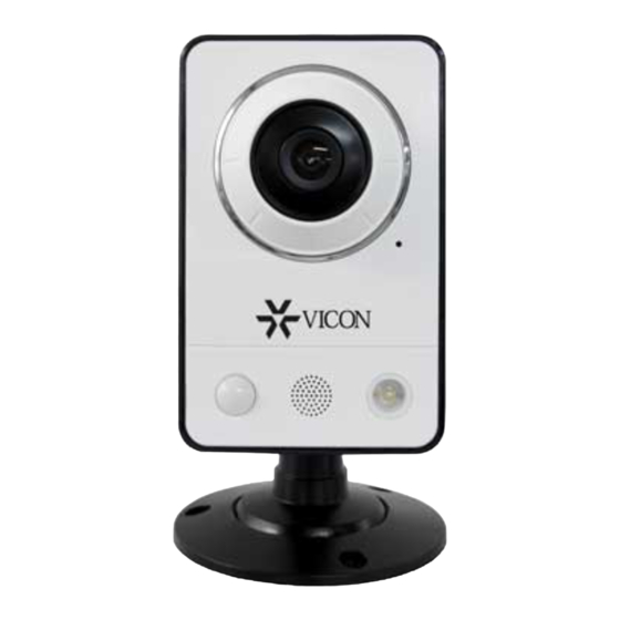
V905-CUBE HD Mini-Cube
Network Camera
Vicon Industries Inc., 89 Arkay Drive, Hauppauge, New York 11788
Tel: 631-952-2288 Fax: 631-951-2288 Toll Free: 800-645-9116
24-Hour Technical Support: 800-34-VICON (800-348-4266) UK: 44/(0) 1489-566300
Vicon Industries Inc. does not warrant that the functions contained in this equipment will meet your requirements or that the
operation will be entirely error free or perform precisely as described in the documentation. This system has not been designed
to be used in life-critical situations and must not be used for this purpose.
www.vicon-security.com
Document Number: 8009-8264-00-00
Issued: 413
Product specifications subject to change without notice.
Copyright © 2013 Vicon Industries Inc. All rights reserved.
Advertisement
Table of Contents

Related Manuals for Vicon V905-CUBE


Summary of Contents for Vicon V905-CUBE
-
Page 1: Network Camera
24-Hour Technical Support: 800-34-VICON (800-348-4266) UK: 44/(0) 1489-566300 Vicon Industries Inc. does not warrant that the functions contained in this equipment will meet your requirements or that the operation will be entirely error free or perform precisely as described in the documentation. This system has not been designed to be used in life-critical situations and must not be used for this purpose. - Page 2 WARNING TO REDUCE THE RISK OF FIRE OR ELECTRIC SHOCK, DO NOT EXPOSE THIS PRODUCT TO RAIN OR MOISTURE. DO NOT INSERT ANY METALLIC OBJECT THROUGH THE VENTILATION GRILLS OR OTHER OPENINGS ON THE EQUIPMENT. APPARATUS SHALL NOT BE EXPOSED TO DRIPPING OR SPLASHING AND THAT NO OBJECTS FILLED WITH LIQUIDS, SUCH AS VASES, SHALL BE PLACED ON THE APPARATUS.
-
Page 3: Fcc Compliance Statement
FCC COMPLIANCE STATEMENT FCC INFORMATION : THIS EQUIPMENT HAS BEEN TESTED AND FOUND TO COMPLY WITH THE LIMITS FOR A CLASS B DIGITAL DEVICE, PURSUANT TO PART 15 OF THE FCC RULES. THESE LIMITS ARE DESIGNED TO PROVIDE REASONABLE PROTECTION AGAINST HARMFUL INTERFERENCE IN A RESIDENTIAL INSTALLATION. - Page 4 THIS PRODUCT IS IN COMPLIANCE WITH THE ESSENTIAL REQUIREMENTS AND OTHER RELEVANT PROVISIONS OF DIRECTIVE 1999/5/EC. THIS DIGITAL EQUIPMENT FULFILLS THE REQUIREMENTS FOR RF EMISSION ACCORDING TO THE CLASS B LIMIT OF EN 55022. THIS PRODUCT FULFILLS THE REQUIREMENTS FOR IMMUNITY ACCORDING TO EN 55024 OFFICE AND COMMERCIAL ENVIRONMENTS.
-
Page 5: Important Safety Instructions
IMPORTANT SAFETY INSTRUCTIONS Read these instructions. Keep these instructions. Heed all warnings. Follow all instructions. Do not use this apparatus near water. Clean only with dry cloth. Do not block any ventilation openings. Install in accordance with the manufacturer’s instructions. Do not install near any heat sources such as radiators, heat registers, stoves, or other apparatus (including amplifiers) that produce heat. -
Page 6: Table Of Contents
Contents 1. Description ------------------------------------------------------------------ 7 1.1 Components -- ------------------------------------------------------------------------------------------- 7 1.2 Key Features - ------------------------------------------------------------------------------------------- 7 1.3 Overview ----- ------------------------------------------------------------------------------------------- 9 2. Installation ----------------------------------------------------------------- 10 2.1 Connection ---- ------------------------------------------------------------------------------------------ 10 2.2 Network Connection and IP Assignment ----------------------------------------------------------- 11 3. Operation -------------------------------------------------------------------- 12 3.1 Access from a browser --------------------------------------------------------------------------------- 12 3.2 Access from the internet ------------------------------------------------------------------------------- 13 3.3 Setting the admin password over a secure connection ------------------------------------------- 13... -
Page 7: Description
1. Description The information in this manual provides quick installation and setup procedures for the V905-CUBE cameras. These units should only be installed by a qualified technician using approved materials in conformance with federal, state, and local codes. Read these instructions thoroughly before beginning an installation. - Page 8 • Image setting adjustment The network camera enables users to adjust image settings such as contrast, brightness and saturation to improve images before encoding takes place. • Intelligent video capabilities The network camera includes intelligent capabilities such as enhanced video motion detection. The external inputs and outputs can be connected to devices such as sensors and relays, enabling the system to react to alarms and activate lights or open/close doors.
-
Page 9: Overview
1.3 Overview • Front View • Rear View Name Description The camera is equipped with a PIR sensor that has a maximum range of PIR Sensor 16 ft (5 m) for detecting movement in the dark. The camera is equipped with a microphone and speaker. Two-way audio Microphone/Speaker support allows for remote users to listen in on an area and communicate with visitors or intruders. -
Page 10: Installation
Camera Dimension Dimensions Unit: mm 2. Installation The network camera is ready for desk-top installation with the stand provided. The stand screws into the hole provided on the back of the camera. 2.1 Connection • Connecting to the RJ-45 Connect a standard RJ-45 cable to the network port of the network camera. -
Page 11: Network Connection And Ip Assignment
2.2 Network Connection and IP assignment The network camera is designed for use on an Ethernet network and requires an IP address for access. Most networks today have a DHCP server that automatically assigns IP addresses to connected devices. By factory default, your camera is set to obtain the IP address automatically via DHCP server. If your network does not have a DHCP server the network camera will use 192.168.1.100 as the default IP address. -
Page 12: Operation
3. Operation The network camera can be used with Windows® operating system and browsers. The recommended browsers are Internet Explorer®, Safari®, Firefox®, Opera® and Google® Chrome® with Windows. Note: To view streaming video in Microsoft® Internet Explorer, set your browser to allow ActiveX controls. -
Page 13: Access From The Internet
3.2. Access from the internet Once connected, the network camera is accessible on your local network (LAN). To access the network camera from the Internet you must configure your broadband router to allow incoming data traffic to the network camera. To do this, enable the NAT-traversal feature, which will attempt to automatically configure the router to allow access to the network camera. -
Page 14: Live View Page
3.4 Live View Page The Live View page provides several screen modes: 1600x1200, 1280x1024, 1280x720, 800x600, 704x480 (576), 640x480, 352x240 (288), and 320x240. Select the most suitable mode in accordance with your PC specifications and monitoring purposes. General controls Live View Page Search &... - Page 15 The Full Screen button causes the video image to fill the entire screen area. No other windows will be visible. Press the 'Esc' button on the computer keyboard to cancel full screen view. The Manual Trigger button activates a pop-up window to manually start or stop the event. Use the Speaker icon scale to control the volume of the speakers.
-
Page 16: Network Camera Setup
3.5 Network Camera Setup This section describes how to configure the network camera, and is intended for product Administrators, who have unrestricted access to all the Setup tools, and Operators, who have access to the settings for Basic, Live View, Video & Image, Audio, Event, and System Configuration. The network camera is configured by clicking Setup in the top right-hand corner of the Live View page. -
Page 17: Users
1) Users User access control is enabled by default. An administrator can set up additional users and passwords. It is also possible to allow anonymous viewer login, which means that anybody may access the Live View page, as described below: The User List displays the authorized users and user groups (levels): User Group Authority... -
Page 18: Network
2) Network The network camera supports both IP version 4 and IP version 6. Both versions may be enabled simultaneously, and at least one version must always be enabled. When using IPv4, the IP address for the network camera can be set automatically via DHCP, or a static IP address can be set manually. If IPv6 is enabled, the network camera receives an IP address according to the configuration in the network router. -
Page 19: Video & Image
3) Video & Image • Sensor Setting Capture Mode: Choose Capture mode to use from the drop-down list: 1600x1200 Max 15 fps: Capture resolution is 1600x1200 and maximum frames per second is 15. 1280x720 Max 30 fps: Capture resolution is 1280x720 and maximum frames per second is 30. - Page 20 Profile: There are 4 pre-programmed stream profiles available for quick set-up. Choose the form of video encoding from the Codec drop-down list: H.264 HP (High Profile): The primary profile for broadcast and disc storage applications, particularly for high- definition television applications (for example, this is the profile adopted by the HD DVD and Blu-Ray Disc).
- Page 21 Select the GOP (Group of Picture) size. If users want to have a high quality of fast image one by one, please decrease the value. For t general monitoring, do not change a basic value; such act may cause a problem to the system performance. Vicon recommends that GOP be the same as the fps.
-
Page 22: Audio
4) Audio The network camera can transmit audio to other clients using an external microphone and can play audio received from other clients by attaching a speaker. The Setup page has an additional menu item called Audio, which allows different audio configurations, such as full duplex. •... -
Page 23: Date & Time
• Audio Output Enable full duplex: Check the box to enable Full Duplex mode. This means that audio (talk and listen) can be transmitted and received at the same time, without having to use any of the controls. This is just like having a telephone conversation. -
Page 24: Video & Image
• New Server Time Select your time zone from the drop-down list. If you want the server clock to automatically adjust for daylight savings time, select the “Automatically adjust for daylight saving time changes”. From the Time Mode section, select the preferred method to use for setting the time: Synchronize with computer time: Sets the time from the clock on your computer. - Page 25 Basic Refer to “3.5.1 Basic Configuration > Video & Image” for more details.
- Page 26 Image • Image Appearance This page provides access to the advanced image settings for the network camera. Brightness: The image brightness can be adjusted in the range 1-10, where a higher value produces a brighter image. Contrast: Adjust the image's contrast by raising or lowering the value, 1-10, in this field. Saturation: Select an appropriate level by entering a value in the range 1-10.
- Page 27 AE & AWB • Exposure Control This page provides access to set the exposure and white balance of the network camera. Configure the exposure settings to suit the image quality requirements in relation to lighting consideration. Mode: Supports exposure modes to control the amount of light detected by the camera sensor based on settings for light conditions.
- Page 28 • White Balance Control This adjusts the relative amount of red, green and blue primary colors in the image so that the neutral colors are reproduced correctly. The camera can be set to automatically adjust for the type of light and compensate for its color. Alternatively, the type of light source can be set manually.
- Page 29 The privacy masks are configured by Mask windows. Each window can be selected by clicking with the mouse. It is also possible to resize, delete, or move the window by selecting the appropriate window from the mouse menu on the video screen. Select “Enable privacy masking”...
-
Page 30: Audio
3.5.3 Audio Refer to “3.5.1 Basic Configuration > Audio” for more details. -
Page 31: Event
3.5.4 Event 1) Event-In On Boot This is used to trigger the event every time the network camera is started. Select “Enable on boot” to activate the motion event. Enter the Dwell time the event lasts from the point of detection, 1-180 seconds. When the settings are complete, click Save, or click Reset to revert to previously saved settings. - Page 32 Manual Trigger This option makes use of the manual trigger button provided on the Live View page, which is used to start or stop the event type manually. Alternatively the event can be triggered via the product's API (Application Programming Interface). Select “Enable manual trigger”...
- Page 33 Motion Motion detection is used to generate an alarm whenever movement occurs (or stops) in the video image. A total of 8 Motion and/or Mask windows can be created and configured. Motion is detected in defined Motion windows, which are placed in the video image to target specific areas.
- Page 34 To create a motion or mask window, follow steps: Click the right button of mouse to see the mouse menu. Select New Motion (or Mask) Window in the mouse menu. Click and drag mouse to designate a motion area. • Motion Detection Setting The behavior for each window is defined by adjusting the Threshold and Sensitivity, as described below.
- Page 35 Network Loss This is used to trigger the event every time the network connection is failed. Select “Enable network loss” to activate the Network Loss event. Select a dwell time for how long the event will last from the point of detection. When the settings are complete, click Save, or click Reset to revert to previously saved settings.
- Page 36 PIR The camera is also able to detect motion using the PIR Sensor. Since the PIR Sensor can detect a moving infrared object such as a person in the dark, it can be used as an intruder alarm when, for example, a thief tries to break into a building at night.
- Page 37 Audio Detection The camera is also able to detect change of the ambient voice using a built-in microphone. Audio detection can be used to measure change in the ambient voice. Select “Enable Audio Detection” to activate the Audio Detection. •...
-
Page 38: Event-Out
2) Event-Out SMTP (E-Mail) The network camera can be configured to send event and error email messages via SMTP (Simple Mail Transfer Protocol). • SMTP(E-Mail) Setting Select “Enable SMTP” to activate the SMTP operation. Sender: Enter the email address to be used as the sender for all messages sent by the network camera. - Page 39 To ensure that the login procedure is performed as securely as possible when using SMTP authentication, you must define the weakest authentication method allowed. Login Method: Set the weakest method allowed to the highest/safest method supported by the mail server. The most secure method is listed in the drop-down list: Auth Login/ Auth Plain •...
- Page 40 actively initiates both the FTP control and data connections to the target server. This is normally desirable if there is a firewall between the camera and the target FTP server. Remote directory: Specify the path to the directory where the uploaded images will be stored.
- Page 41 • HTTP Server Setting URL: The network address to the server and the script that will handle the request. For example: http://192.168.12.244/cgi-bin/upload.cgi Port: Enter the port number used by the HTTP server. The default is 80. User name/Password: Provide your log-in information. •...
- Page 42 ▼ Record When the network camera detects an event, it can record video stream in the Micro SD Memory (not supplied) or NAS (Network Attached Device) as a storage device. Check the "Enable Record" box to enable the service. • Record Setting Overwrite: Click checkbox to overwrite the storage device;...
-
Page 43: Device Information
Note1: Common Internet File System (CIFS) is a remote file access protocol that forms the basis for Windows file sharing, network printing, and various other network services. CIFS requires a large number of request/response transactions and its performance degrades significantly over high-latency WAN links such as the Internet. Note2: Network File System (NFS) is a network file system protocol, allowing a user on a client computer to access files over a network in a manner similar to how local storage is accessed. - Page 44 ▼ Light The LED on the front of the camera can be set to flash at a configurable interval when an event is triggered. • Enable light: Select “Enable light” to activate the light operation. Keep active during event: Select checkbox for the light to stay on during event dwell time.
- Page 45 ▼ Event Notification When the network camera detects an event, Notification Server is used to receive notification messages as a type of XML data format. Check the box to enable event notification. • Event Notification Setting Notification Server URL: The network address to the server and the script that will handle the request.
- Page 46 ▼ Boost The Boost feature is used in conjunction with event detection. When this feature is turned ON, the Framerate and Bitrate in the boost condition can be set to a different value than those in the normal condition field. When an event is detected, the camera will boost the Framerate and Bitrate from the normal condition to this boosted level for the duration of the event.
-
Page 47: Event Map
3) Event Map The event map allows you to change the settings and establish a schedule for each event trigger from the network camera; up to a max. 15 events can be registered. Click the Add button to make a new event map; a popup window displays as below. To change an existing event, select that event and click the Modify button;... - Page 48 • General Enter the name for a new event map. • Event In Select an event type in the drop down list. • Event Out Select checkbox for those features you want to use. E-mail: Select email addresses you want to send via email that an event has occurred. FTP: Record and save images to an FTP server when an event has occurred.
-
Page 49: System
3.5.5 System 1) Information You can enter the system information. This page is very useful when you refer device information after installation. • Device Name Configuration Enter the device name. • Location Configuration Enter the location information. You can enter up to four locations. When the settings are complete, click Save, or click Reset to revert to previously saved settings. -
Page 50: Security
2) Security Users User access control is enabled by default, when the administrator sets the root password on first access. New users are authorized with user names and passwords, or the administrator can choose to allow anonymous viewer login to the Live View page, as described below: •... - Page 51 HTTPS For greater security, the network camera can be configured to use HTTPS (Hypertext Transfer Protocol over SSL (Secure Socket Layer)), so that all communication that would otherwise go via HTTP will instead go via an encrypted HTTPS connection. •...
- Page 52 IP Filtering Checking the "Enable IP address filtering" box enables the IP address filtering function. Up to 256 IP address entries may be specified (a single entry can contain multiple IP addresses). Click the Add button to add new filtered addresses. When the IP address filter is enabled, addresses added to the list are set as allowed or denied addresses.
-
Page 53: Date & Time
3) Date & Time • Current Server Time This displays the current date and time (24h clock). The time can be displayed in 12h clock format (see below). • New Server Time Select your time zone from the drop-down list. If you want the server clock to automatically adjust for daylight savings time, select “Automatically adjust for daylight saving time changes”. -
Page 54: Network
4) Network Settings regarding the network can be executed. Settings for IP, DNS, Host Name, Port, and ARP/Ping can be established, along with setting for DDNS, uPnP, QoS, Zeroconfig, Bonjour, Live Push, Hole Punching, and wireless. Basic • IP Address Configuration: Obtain IP address via DHCP: Dynamic Host Configuration Protocol (DHCP) is a protocol that lets network administrators centrally manage and automate the assignment of IP addresses on a network. - Page 55 • IPv6 Address Configuration Check this box to enable IPv6. Other settings for IPv6 are configured in the network router. • DNS Configuration DNS (Domain Name Service) provides the translation of host names to IP addresses on your network. Obtain DNS Server via DHCP: Automatically use the DNS server settings provided by the DHCP server.
- Page 56 DDNS • Internet DDNS (Dynamic Domain Name Service) When using the high-speed Internet with the telephone or cable network, users can operate the network camera on the floating IP environment in which IPs are changed at every access. Users should receive an account and password by visiting a DDNS service like http://www.dyndns.com/, or http://www.cctv-network.co.kr/.
- Page 57 RTP Create a setting for sending and receiving an audio or video on a real-time basis. These settings are the IP address, port number, and Time-To-Live value (TTL) to use for the media stream(s) in multicast H.264 format. Only certain IP addresses and port numbers should be used for multicast streams.
- Page 58 UPnP The network camera includes support for UPnP™. UPnP is enabled by default, and the network camera then is automatically detected by operating systems and clients that support this protocol. Enter a name in the Friendly name field. Note: UPnP™ must be installed on your workstation if running Windows XP. To do this, open the Control Panel from the Start Menu and select Add/Remove Programs.
- Page 59 QoS Quality of Service (QoS) provides the means to guarantee a certain level of a specified resource to selected traffic on a network. Quality can be defined as a maintained level of bandwidth, low latency, and no packet losses. The main benefits of a QoS-aware network are: The ability to prioritize traffic and thus allow critical flows to be served before flows with lesser priority.
- Page 60 • Auto Traffic Control Check the box to enable automatic traffic control. Set a limitation on user network resources by designating the maximum bandwidth. Maximum bandwidth: When sharing other network programs or equipment, it is possible to set a limitation on the maximum bandwidth in the unit of Mbit/s or kbit/s. Auto frame rate: Selected if not influenced by a network-related program or equipment without a limitation on the network bandwidth.
- Page 61 • NAT Traversal Settings Enable: Check this box to enable NAT traversal. When enabled, the network camera attempts to configure port mapping in a NAT router on your network, using UPnP™. Note that UPnP must be enabled in the network camera (see System>Network>UPnP). Automatic setting: When selected, the network camera automatically searches for NAT routers on your network.
- Page 62 Zeroconfig Zeroconfig allows the network camera to create and assign IP address for network cameras and connect to a network automatically. Zero configuration networking (zeroconf), is a set of techniques that automatically creates a usable Internet Protocol (IP) network without manual operator intervention or special configuration servers. Zero configuration networking allows devices such as computers and printers to connect to a network automatically.
- Page 63 Bonjour The network camera includes support for Bonjour. When enabled, the network camera is automatically detected by operating systems and clients that support this protocol. Click the check box to enable Bonjour. Enter a name in the Friendly name field. When the settings are complete, click Save, or click Reset to revert to previously saved settings.
- Page 64 Live Push • Live Push Configuration When this function is activated, the network camera as a client can transfer audio, video and event data to the registered server. The network camera and server use RTP/RTSP as the protocol for the actual transport of audio/video data.
-
Page 65: Language
VSAAS • VSAAS Configuration VSAAS Server URL: Enter the third-party server’s URL that uncovers external and internal address information. Port: Enter the port number used by the VSAAS server. The default is 80. Note: Video Surveillance as a Service (VSaaS) refers to hosted/Internet recording of security camera video. -
Page 66: Maintenance
6) Maintenance • Maintenance Server Restart: The unit is restarted without changing any of the settings. Use this method if the unit is not behaving as expected. Restore: The unit is restarted and most current settings are reset to factory default values. The settings that are not affected are: * the boot protocol (DHCP or static) * the static IP address... -
Page 67: Support
7) Support The support page provides valuable information when troubleshooting a problem or when contacting technical assistance. • Logs The network camera supports system log information. Click the System Log button to get the log data. • Reports Server Report: Click the Server Report button to get the important information about the server’s status;... - Page 68 Media Check: Click the Media Check button to get information about the camera’s video and audio stream. The pop-up window below displays. Network Check: Click the Network Check button to get information about the camera’s network setting and traffic. The pop-up window below displays.
- Page 69 Hardware Check: Click the Hardware Check button to diagnose the camera’s hardware like video, LED and PIR sensor. You can see the pop-up window below.
-
Page 70: Playback
3.6 Playback The Playback window contains a list of recordings made to the memory card. It shows each recording's start time, length, the event type used to start the recording; the calendar and time slice bar indicate if the recording is exists or not. - Page 71 Go to Last: go to the last of the video clip. Clip copy: copy the video clip. Zoom In: zoom in the video clip Full Screen: display full screen of the video. (3) Time Chart Display an hour-based search screen for the chosen date. If there is recording data, a blue section will be displayed on a 24-hour basis.
-
Page 72: Help
3.7 Help The Help information window is provided as a popup window so that users can open and read it without a need for log-in. It offers descriptions of settings and a Help page, so users can manipulate the network camera without having to reference the manual. -
Page 73: Resetting To The Factory Default Settings
3.8 Resetting to the factory default settings To reset the network camera to the original factory settings, go to the Setup>System> Maintenance web page (described in “3.5.5 System > Maintenance”) or use the Reset button on the network camera, as described below: •... -
Page 74: Appendix
4. Appendix 4.1 Troubleshooting When troubleshooting if problems occur, verify the installation of the network camera with the instructions in this manual and with other operating equipment. Isolate the problem to the specific piece of equipment in the system and refer to the equipment manual for further information. Problems/Symptoms Possible Causes or Corrective Actions The camera cannot be accessed... -
Page 75: Preventive Maintenance
4.2 Preventive Maintenance Preventive maintenance allows detection and correction of minor faults before they become serious and cause equipment failure. Every three-month, perform the following maintenance. Inspect all connection cables for deterioration or other damage. Clean components with a clean damp cloth. Verify that all the mounting hardware is secure. -
Page 76: Product Specification
4.3 Product Specification Main Item Specification Image sensor 1/4” Progressive scan RGB CMOS Active Array 1600(H) x 1200(V) Lens Fixed 2.6mm Lens, F1.8 Angle of View 80.7°(H) x 58.7(V) x 103.2°(D) Min. illumination Color: 1Lux(LED Off), 0Lux (LED On) Shutter Speed 1/20,000 ~ 1/30 (Slow shutter 1/15, 1/8 and 1/4) -. -
Page 77: System Requirement For Web Browser
System Requirement for Web Browser Operating System: Microsoft Windows 98, Microsoft Windows ME, Microsoft Windows 2000, Microsoft Windows XP, or Microsoft Windows Vista CPU: Intel® Core® 2 Duo 2GHz or higher, 1GB RAM or more, 10GB free disk or higher VGA: AGP, Video RAM 32MB or higher (1024x768, 24bpp or higher) -
Page 78: Shipping Instructions
Shipping Instructions Use the following procedure when returning a unit to the factory: 1. Call or write Vicon for a Return Authorization (R.A.) at one of the locations listed below. Record the name of the Vicon employee who issued the R.A. -
Page 79: Vicon Standard Equipment Warranty
“autopan” or “tour” modes of operation. Such continuous operation is outside the scope of this warranty. Any product sold as “special” or not listed in Vicon’s commercial price list: One year from date of original retail purchase. - Page 80 Vicon Industries Inc. Corporate Headquarters 89 Arkay Drive Hauppauge, New York 11788 631-952-2288 800-645-9116 Fax: 631-951-2288 Vicon Europe Headquarters Brunel Way Fareham, PO15 5TX United Kingdom +44 (0) 1489 566300 Fax: +44 (0) 1489 566322 Vicon Germany Kornstieg 3 D-24537 Neumuenster...
Need help?
Do you have a question about the V905-CUBE and is the answer not in the manual?
Questions and answers