Advertisement
Thank you very much for purchasing DELTA A Series. Please read this instruction sheet before using your A series to ensure proper
operation and please keep this instruction sheet handy for quick reference.
Precaution
DANGER! Caution! Electric Shock!
1.
Do not touch the AC terminals while the power is supplied to the controller to prevent an electric shock.
2.
Make sure power is disconnected while checking the unit inside.
3.
The symbol
indicates that this Delta A Series Temperature Controller is protected throughout by DOUBLE INSULATION or
REINFORCED INSULATION (equivalent to Class II of IEC 536).
WARNING!
This controller is an open-type temperature controller. Make sure to evaluate any dangerous application in which a serious human
injury or serious property damage may occur.
1. Always use recommended solder-less terminals: Fork terminal with isolation (M3 screw, width is 7.0mm, hole diameter 3.2mm).
Screw size: M3 x 6.5 (With 6.8 x 6.8 square washer).
Recommended tightening torque: 0.4 N.m (4kgf.cm).
Applicable wire: Solid/twisted wire of 2 mm
Please be sure to tighten them properly.
2. Do not allow dust or foreign objects to fall inside the controller to prevent it from malfunctioning.
3. Never modify or disassemble the controller.
4. Do not connect anything to the "No used" terminals.
5. Make sure all wires are connected to the correct polarity of terminals.
6. Do not install and/or use the controller in places subject to:
•
Dust or corrosive gases and liquid.
High humidity.
•
•
High radiation.
•
Vibration and shock.
•
High voltage and high frequency
7. Must turn power off when wiring and changing a temperature sensor.
8. Be sure to use compensating wires that match the thermocouple types when extending or connecting the thermocouple wires.
9. Please use wires with resistance when extending or connecting a platinum resistance thermometer (RTD).
10. Please keep the wire as short as possible when wiring a platinum resistance thermometer (RTD) to the controller and please route power
wires as far as possible from load wires to prevent interference and induced noise.
11. This controller is an open-type unit and must be placed in an enclosure away from high temperature, humidity, dripping water, corrosive
materials, airborne dust and electric shock or vibration.
12. Please make sure power cables and signals from instruments are all installed properly before energizing the controller, otherwise serious
damage may occur.
13. Please do not touch the terminals in the controller or try to repair the controller when power is applied to prevent an electric shock.
14. Wait at least one minute after power is disconnected to allow capacitors to discharge, and please do not touch any internal circuit within
this period.
15. Do not use acid or alkaline liquids for cleaning. Please use a soft, dry cloth to clean the controller.
16. This instrument is not furnished with a power switch or fuse. Therefore, if a fuse or power supply switch is required, install the protection
close to the instrument.
Recommended fuse rating: Rated voltage 250 V, Rated current 1 A.
Fuse type: Time-lag fuse
Note: This controller does not provide overcurrent protection. Use of this product requires that suitable overcurrent protection device(s)
must be added to ensure compliance with all relevant electrical standards and codes. (Rated 250 V, 15 Amps max). A suitable
disconnecting device should be provided near the controller in the end-use installation.
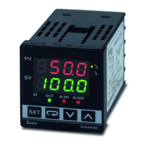
Series Temperature Controller
Instruction Sheet
2
, 12AWG to 24AWG.
- 1 -
2013/03/27
Advertisement
Table of Contents

Related Manuals for Delta A Series


Summary of Contents for Delta A Series
- Page 1 2013/03/27 Series Temperature Controller Instruction Sheet Thank you very much for purchasing DELTA A Series. Please read this instruction sheet before using your A series to ensure proper operation and please keep this instruction sheet handy for quick reference. Precaution DANGER! Caution! Electric Shock! Do not touch the AC terminals while the power is supplied to the controller to prevent an electric shock.
-
Page 2: Ordering Information
Ordering Information Series DTA: Delta A Series Temperature Controller 4848: 1/16 DIN W48 × H48mm Panel Size 9648: 1/8 DIN W96 x H48 4896: 1/8 DIN W48 × H96mm (W × H) 9696: 1/4 DIN W96 × H96mm 7272: W72 × H72mm R: Relay output, SPDT (SPST: 1/16 DIN size), 250VAC, 5A V: Voltage Pulse output, 14V+10% ~ -20% (Max. -
Page 3: Parameters List
Storage temperature C ~ +65 Relative humidity 35% ~ 80% (non-condensing) Altitude 2,000m or less Installation Category 33, Pollution Degree 2. Conforming to EN61010-1 Installation environment Panel protection level IP65 Parameters List 1. Operation Mode: Perform per the settings of related control parameters LED Display Explanation Default... -
Page 4: Operation
LED Display Explanation Default T-LOW: Lower limit for temperature range -20.0 CONTROL: Control method setting on the SV display: PID ( ), ON/OFF control ( ), or manual tuning ( HEAT SWITCH: Select Heating ( ) or Cooling ( ) action AL1 SET: Alarm 1 setting (See explanations in “Alarm Outputs”... -
Page 5: Heating And Cooling Control
Regulation Mode Operation Mode Initial Setting Mode Upper-limit alarm 2 Select control mode P/PD control offset (This parameter is available only when ALA2 setting function enables) (When PID control is ON and Ki=0, set the value of Pdof; if Ki≠0, AT will automatically set the value of Iof) Press Press... -
Page 6: Alarm Outputs
Temperature Sensor Type & Temperature Range Input temperature sensor type Register value LED display Temperature range Platinum resistance (Pt100) type 3 0.0 ~ 100.0 Platinum resistance (Pt100) type 2 -20.0 ~ 500.0 Platinum resistance (Pt100) type 1 -200 ~ 600 Platinum resistance (JPt100) type 2 0.0 ~ 100.0 Platinum resistance (JPt100) type 1... - Page 7 Set value Alarm type Alarm output operation Reverse deviation upper- and lower-limit: This alarm output operates when PV value is in the range of the setting value SV + (AL-H) and SV - (AL-L). SV-(AL-L) SV+(AL-H) Absolute value upper- and lower-limit: This alarm output operates when PV value is higher than the setting value AL-H or lower than AL-H setting value AL-L.
- Page 8 Address Content Explanation 4707H Lower-limit of temperature range The data content should not be lower than the temperature range 4708H PB Proportional band 0.1 ~ 999.9, Unit: 0.1 4709H Ti Integral time 0 ~ 9,999 470AH Td Derivative time 0 ~ 9,999 470BH Heating/Cooling hysteresis 0 ~ 9,999...
-
Page 9: Communication Protocol
Communication Protocol Command code to read N words: 03H. The maximum value of N is 3. For example, in order to read two words from controller 01 (address 01H) at starting data address 4700H, the command in ASCII mode is: ASCII mode: Command message: Response message:... -
Page 10: Terminal Identification
Terminal Identification DTA4848 AC 100~240V 5A 250Vac 14Vdc DC 4~20mA 50~60Hz /5VA ALM2 DATA- ALM1 3A 250Vac 3A 250Vac RS-485 DATA+ DTA7272 DTA4896/DTA9648/DTA9696 DATA+ AC 100~240V DATA+ RS-485 50~60Hz /5VA AC 100~240V RS-485 DATA- 50~60Hz /5VA DATA- 3A 250Vac 3A 250Vac ALM2 ALM2 ALM1... - Page 11 Panel Cutout & External Dimensions 1. Panel wall thickness should range from 1mm to 8mm 2. Provide at least 90 mm clearance around the controller for proper ventilation. (Dimensions are in millimeter and (inch)) DTA4848 65.0 min. +0.6 DTA4896 DTA9648 DTA7272 - 11 -...
- Page 12 DTA9696 CT Wiring Method (if CT function is selected) - 12 -...
Need help?
Do you have a question about the A Series and is the answer not in the manual?
Questions and answers