Advertisement
Thank you very much for choosing Delta DTE series temperature controller. Please read this instruction sheet carefully before using your
DTE to ensure proper operation. Keep this instruction sheet handy for quick reference.
Warning
DANGER! CAUTION! ELECTRIC SHOCK!
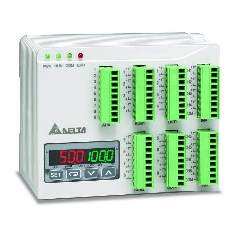
DTE is an OPEN-TYPE device and therefore should be installed in an enclosure free of airborne dust, humidity, electric shock
and vibration. The enclosure should prevent non-maintenance staff from operating the device (e.g. key or specific tools are
required for opening the enclosure) in case danger and damage on the device may occur.
1. Prevent dust or metallic debris from falling into the device and cause malfunctions. DO NOT modify or uninstall the circuit board of DTE
without being permitted. DO NOT use empty terminals.
2. Keep away from high-voltage and high-frequency environment during the installation in case of interference. Prevent using the device in
premises which contain:
(a) dust or corrosive gas; (b) high humidity and high radiation; (c) shock and vibration.
3. The power has to be switched off when wiring or changing the temperature sensor.
4. When installing the circuit board of the accessory, please make sure the power of the main unit is switched off and insert the accessory
into the correct slot on the main unit.
5. Make sure to use compensation wire which matches the thermocouple or platinum resistance when extending or connecting the
thermocouple or platinum resistance.
6. Keep the wire as short as possible when wiring a sensor to the controller. Separate the power cable and load wire in order to prevent
interference and induced noise.
7. Make sure the power cables and signal device are installed correctly before switching on the power; otherwise serious damage may
occur.
8. DO NOT touch the terminal or repair the device when the power is on; otherwise an electric shock may occur.
9. Please wait for 1 minute after the power is switched off to allow the capacitor to discharge and DO NOT touch the internal wiring within
this period.
10. DO NOT touch the internal terminal when DTE is either switched on or off in case you may damage the circuit.
11. Please place DTE with other heating objects (e.g. power supply) within proper distance while installing DTE.
Ordering Information
Series name
DTE: Delta E series temperature controller
1
Device type
0T: 4-channel TC
2
3
-
4
0P: 3-channel PT
Functions & Electrical Specifications
Power input
24 VDC, isolated switching power supply
Voltage range
90 to 110% rated voltage
Power consumption
Max. 10 W + 3 W × number of DTC2000 controllers connected in parallel (Max. 7)
Thermocouple: K, J, T, E, N, R, S, B, L, U, TXK
Input sensor
Platinum resistance: Pt100, JPt100, Cu50, Ni120
Sampling cycle
Thermocouple or platinum resistance: 1.0 second/all input
Control method
PID, PID programmable, manual, ON/OFF
Relay output: SPST, Max. 250 VAC load, 3A resistive load
Output accessories
Voltage pulse output: 12 VDC, Max. 40 mA current output
(optional)
Current output: DC 4 to 20 mA output (resistive load < 500 Ω); for OUT1 and OUT2 only
Series Temperature Controller Instruction Sheet
1: main unit
0T: 4 - channel TC
0P: 3 - channel PT
0V: 4 channels of voltage pulse output
0C: 4 channels of linear current output
0R: 4 channels of relay output
0L: 4 channels of linear voltage output
2: accessory
DS: Display and setup module
CT: 4 channels of current transformer
sensors
0D: 8-channel EVENT input
1
2019/01/22
Advertisement
Table of Contents

Related Manuals for Delta DTE Series


Summary of Contents for Delta DTE Series
- Page 1 2019/01/22 Series Temperature Controller Instruction Sheet Thank you very much for choosing Delta DTE series temperature controller. Please read this instruction sheet carefully before using your DTE to ensure proper operation. Keep this instruction sheet handy for quick reference. Warning...
-
Page 2: Product Profile & Outline
Analog voltage output: 0 to 10 V (resistive load > 1,000 Ω); for OUT1 and OUT2 only Control output, alarm output or proportional output (proportional output is only applicable in the model with linear Output functions voltage and current output for OUT1, OUT2) Alarm modes 13 alarm modes available Communication... - Page 3 The standard DTE main unit is attached with 3 channels of inputs. You can purchase additional DTE20P to expand the number of input channels. DTE supports maximum 6 channels of inputs which belong to group INA and group INB. Each group possesses 3 input channels. DTE series supports the following input sensors: Input Sensor Type...
-
Page 4: Led Display
Table 3 When there are only 3 channels of inputs, SUB1 cannot be used for alarm output but heating/cooling control only. When there are only 3 channels of inputs, OUT2 and SUB2 cannot be set up by the user but set up automatically as "alarm output” by the controller. -
Page 5: Channel Disable
4. Any of the input temperatures has not been stabilized. 5. Input signal error. 6. The Input low voltage (less than 4V) Synchronous Communication Protocol & Auto ID Setup This function allows the auto setup of communication protocol in extension module DTC2000 and DTC2001 following the communication protocol set in the DTE main unit. -
Page 6: Event Input
INA input: OUT1 control mode 10A8H 10A9H 10AAH OUT2 control mode 10B0H 10B1H 10B2H Alarm 1 output mode 10C0H 10C1H 10C2H Alarm 2 output mode 10C4H 10C5H 10C6H Upper bound of Alarm 1 output 1080H 1081H 1082H Lower bound of Alarm 1 output 1088H 1089H 108AH... - Page 7 2. Each channel can be set up individually for specific functions. Addresses: Address for the 1998H 1999H 199AH 199BH 199CH 199DH EVENT function Functions: Set value RUN (open circuit) SV1 (open circuit) Auto (open circuit) Execute (open circuit) Function STOP (short circuit) SV2 (short circuit) Manual (short circuit) Pause (short circuit)
-
Page 8: Delayed Alarm
Opposite Output Function The 6 channels on DTE10P can be set to opposite output, that is, when the output is set to 0, the actual output will be 1. How to Operate To set CH1 and CH3 to opposite output, first write 1234H into the address 47F1H and then 0005H into address 4821H to set on CH1 (bit0) and CH3 (bit2). -
Page 9: Hot Runner Control
suppress interferences. How to Operate Set up relevant parameters using the table below. Parameter Address Default value Range Filter times 10F7H 0~50 Filter range 10F9H 0.1~10.0 Hot Runner Control Function The hot runner control includes 3 steps: 1. Heating up by constant output volume 2. - Page 10 Content Explanation H1010 H1011 H1012 H1013 H1014 H1015 Disabled when higher than Max. temperature value default value (H1102) (H1202) (H1302) (H1402) (H1502) (H1602) H1018 H1019 H101A H101B H101C H101D Disabled when lower than Min. temperature value default value (H1103) (H1203) (H1303) (H1403) (H1503)
- Page 11 Content Explanation 1: executing (H111B) (H121B) (H131B) (H141B) (H151B) (H161B) 2: program stops 3: program pauses H10E0 H10E1 H10E2 H10E3 H10E4 H10E5 0: stop Status of PID auto-tuning 1: executing (H111C) (H121C) (H131C) (H141C) (H151C) (H161C) H10E8 H10E9 H10EA H10EB H10EC H10ED Positive/negative...
- Page 12 Content Explanation Pattern 0 Pattern 1 Pattern 2 Pattern 3 Pattern 4 Pattern 5 Pattern 6 Pattern 7 0 ~ 8: 8 refers to end of NO. of current link program; 0 ~ 7 refer to the H2078 H2079 H207A H207B H207C H207D...
- Page 13 Multi Write Command Multi Write Response Command ‘0’ End word 0 ‘6’ ‘0’ ‘0’ ‘0’ Write data content 2 ‘1’ ‘5’ LRC1 check ‘F’ LRC0 check ‘4’ End word 1 End word 0 LRC Check: Sum up the contents from “machine address” to “data content”, e.g. H01 + H03 + H10 + H00 + H00 + H02 = H16. Obtain 2’scomplement HEA.
- Page 14 Software for Setting up Communication on PC: Download the free software on Delta’s website. How to Mount & DIN Rail Size Connect maximum 7 DTC2000 or DTC2001 controllers to DTE by using DIN rail.
Need help?
Do you have a question about the DTE Series and is the answer not in the manual?
Questions and answers