Advertisement
2005-09-21
Http://www.delta.com.tw/industrialautomation
5011615707-DAE7
A Series Temperature Controller
Instruction Sheet
Thank you very much for purchasing DELTA A Series. Please read this instruction sheet
before using your A series to ensure proper operation and please keep this instruction
sheet handy for quick reference.
Precaution
DANGER! Caution! Electric Shock!
1. Do not touch the AC terminals while the power is supplied to the controller to
prevent an electric shock.
2. Make sure power is disconnected while checking the unit inside.
3. The symbol
indicates that this Delta A Series Temperature Controller is
protected throughout by DOUBLE INSULATION or REINFORCED INSULATION
(equivalent to Class II of IEC 536).
WARNING!
This controller is an open-type temperature controller. Make sure to evaluate any
dangerous application in which a serious human injury or serious property damage
may occur.
1. Always use recommended solder-less terminals: Fork terminal with isolation (M3
screw, width is 7.0mm, hole diameter 3.2mm).
Screw size: M3 x 6.5 (With 6.8 x 6.8 square washer).
Recommended tightening torque: 0.4 N.m (4kgf.cm).
2
Applicable wire: Solid/twisted wire of 2 mm
, 12AWG to 24AWG.
Please be sure to tighten them properly.
2. Do not allow dust or foreign objects to fall inside the controller to prevent it from
malfunctioning.
3. Never modify or disassemble the controller.
4. Do not connect anything to the "No used" terminals.
5. Make sure all wires are connected to the correct polarity of terminals.
6. Do not install and/or use the controller in places subject to:
•
Dust or corrosive gases and liquid.
•
High humidity.
•
High radiation.
•
Vibration and shock.
•
High voltage and high frequency
7. Must turn power off when wiring and changing a temperature sensor.
8. Be sure to use compensating wires that match the thermocouple types when
extending or connecting the thermocouple wires.
9. Please use wires with resistance when extending or connecting a platinum
resistance thermometer (RTD).
10. Please keep the wire as short as possible when wiring a platinum resistance
thermometer (RTD) to the controller and please route power wires as far as
possible from load wires to prevent interference and induced noise.
11. This controller is an open-type unit and must be placed in an enclosure away from
high temperature, humidity, dripping water, corrosive materials, airborne dust and
electric shock or vibration.
12. Please make sure power cables and signals from instruments are all installed
properly before energizing the controller, otherwise serious damage may occur.
13. Please do not touch the terminals in the controller or try to repair the controller
when power is applied to prevent an electric shock.
14. Wait at least one minute after power is disconnected to allow capacitors to
discharge, and please do not touch any internal circuit within this period.
15. Do not use acid or alkaline liquids for cleaning. Please use a soft, dry cloth to
clean the controller.
16. This instrument is not furnished with a power switch or fuse. Therefore, if a fuse or
power supply switch is required, install the protection close to the instrument.
Recommended fuse rating: Rated voltage 250 V, Rated current 1 A.
Fuse type: Time-lag fuse
Note: This controller does not provide overcurrent protection. Use of this product
requires that suitable overcurrent protection device(s) must be added to ensure
compliance with all relevant electrical standards and codes. (Rated 250 V, 15
Amps max). A suitable disconnecting device should be provided near the
controller in the end-use installation.
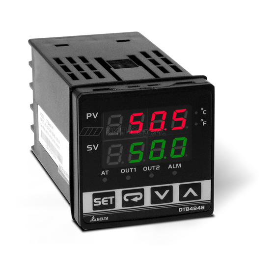
Display, LED and Pushbuttons
• PV Display : to display the process value or parameter type.
• SV Display : to display set point, parameter operation read value, manipulated
variable or set value of the parameter.
• AT : flashes when the Auto-tuning operation is ON.
• OUT : lights when the output is ON.
•
: Function key. 1. Press this key to select the desired function mode.
2. Press this key to confirm a setting value.
•
: Mode key. Press this key to set parameters within each function mode.
o
o
o
•
C,
F : Temperature unit LEDs.
C LED lights when this parameter is configured for
o
Celsius and
F LED lights if configured for Fahrenheit.
• ALM1 / ALM2 : Alarm output LED. The ALM1 / ALM2 LED lights when Alarm 1 or
Alarm 2 output is ON.
•
: Up key. Press this key to increase values displayed on the SV display. Hold
down this key to speed up the incremental action.
•
: Down key. Press this key to decrease values displayed on the SV display. Hold
down this key to speed up the decrements.
Specifications
Input Voltage
100 to 240VAC
50/60Hz
Operation Voltage Range
85% to 110% of rated voltage
Power Consumption
5VA max.
7-segment digit LED Display
Display Method
Process value (PV): Red color, Set point (SV): Green color
Thermocouple: K, J, T, E, N, R, S, B, U, L, Txk
Sensor Type
3-wire Platinum RTD: Pt100, JPt100
Control Mode
PID, ON/OFF control or Manual tuning
Relay output:(resistive load): SPDT (SPST: 1/16 DIN size),
250VAC, 5A
Control Output
Voltage Pulse output: DC 14V, Max. load current 40mA
Current output: 4 to 20mADC (Load resistance: Max. 600Ω)
Display Accuracy
0.1% of measuring range
Sampling Rate
500 msec/per scan
2
Vibration Resistance
10 to 55Hz, 10m/s
for 10min, each in X, Y and Z directions
2
Shock Resistance
Max. 300m/ s
, 3 times in each 3 axes, 6 directions
o
o
Ambient Temperature
0
C to +50
C
o
o
Storage Temperature
-20
C to +65
C
Relative Humidity
35% to 80% (non-condensing)
Altitude
2000m or less
Installation Category 33, Pollution Degree 2. Conforming to
Installation Environment
EN61010-1
Parameters List
1. Operation Mode: Perform per the settings of related control parameters
LED Display
Explanation
RUN/STOP: Control setting begins. Run (
) or Stop
(
) mode on the SV display.
ALARM1 HIGH: Upper-limit alarm 1
ALARM1 LOW: Lower-limit alarm 1
ALARM2 HIGH: Upper-limit alarm 2
ALARM2 LOW: Lower-limit alarm 2
Setting lock: Lock 1 (
), Lock 2 (
) or OFF
(
) on the SV display. Lock 1 mode can lock all settings
and Lock 2 mode only can lock others than SV value. When
OFF mode is selected, the Lock function will be OFF. If you
press
and
key simultaneously, the "Lock" status can
be released and the controller will be back to the previous
display.
OUT: Output value display and output value adjustment in
manual tuning control (This function is not available in
ON/OFF control or Auto-tuning setting)
CT: In case of using an external current transformer (CT), the
controller displays the current value being measured by CT, if
the control output is ON
2. Regulation Mode: Set the control parameters
LED Display
Explanation
AT: Auto-tuning setting. When AT key is set to ON (
the execution of the PID auto-tuning function is automatically
started. (PID control)
P: Proportional Band (PID control)
I: Integral Time (PID control)
D: Derivative Time (PID control)
PdoF: Offset output when P or PD control function is ON. (PID
control and Ki=0)
ioF: Default value of integral volume when PID control function
is ON and integral time constant is not equal to 0(zero). AT
can automatically set this parameter. (PID control and Ki≠0)
HTS: Set Heating hysteresis when ON/OFF control function is
ON.
CTS: Set Cooling hysteresis when ON/OFF control function is
ON.
HTPD: PID heating control cycle setting (PID control)
CLPD: PID cooling control cycle setting (PID control)
TPOF: Regulate temperature deviation value
CRHI: Regulate 20mA output deviation value
CRLO: Regulate 4mA output deviation value
3. Initial Setting Mode: Initial settings of the controller and communication
parameters
LED Display
Explanation
INPUT: Select input temperature sensor type
(Please refer to the contents of the "Temperature Sensor Type
and Temperature Range" for detail)
o
o
UNIT: Temperature display unit,
C
(
) and
F
(
)
T-HIGH: Upper limit for temperature range
T-LOW: Lower limit for temperature range
CONTROL: Control method setting on the SV display: PID
(
), ON/OFF control (
(
)
SWITCH: Select Heating (
) or Cooling (
action
AL1 SET: Alarm 1 setting
AL2 SET: Alarm 2 setting
C WE: Write-in function disable/enable
(Displayed when using serial communication)
C NO: Address setting
(Displayed when using serial communication)
BPS: Baud rate setting
(Displayed when using serial communication)
LENGTH: Data length setting
(Displayed when using serial communication)
PARITY: Parity bit setting
(Displayed when using serial communication)
STOP BIT: Stop bit setting
(Displayed when using serial communication)
Note: Alarm values should be set in the initial setting mode so AL1H, AL1L, AL2H
and AL2L would display in operation mode.
Heating and Cooling Control
Temperature control is achieved either by heating or by cooling. The heating function
starts when the process temperature (PV) is going down, and the cooling function when
the temperature is getting high. It is impossible to operate both functions simultaneously
in this controller.
Temperature Sensor Type and Temperature Range
Default
Register
RUN
Input Temperature Sensor Type
Value
Platinum resistance (Pt100) type3
15
o
4.0
C
Platinum resistance (Pt100) type2
14
o
4.0
C
o
Platinum resistance (Pt100) type1
13
4.0
C
Platinum resistance (JPt100) type2
12
o
4.0
C
Platinum resistance (JPt100) type1
11
Thermocouple (TC) B type
10
OFF
Thermocouple (TC) S type
9
Thermocouple (TC) R type
8
Thermocouple (TC) N type
7
Thermocouple (TC) E type
6
0
Thermocouple (TC) T type2
5
Read only
Thermocouple (TC) T type1
4
Thermocouple (TC) J type2
3
Thermocouple (TC) J type1
2
Default
),
Thermocouple (TC) K type2
1
OFF
Thermocouple (TC) K type1
0
47.6
Thermocouple (TC) L type
16
260
Thermocouple (TC) U type
17
41
Thermocouple (TC) Txk type
18
0
Input Error Indication
Setting
Temperature sensor is
Measured temperature value
value
not connected
exceeds the temperature range
0
PV
0
SV
0
Operation
Output
There are three modes of operation: operation, regulation and initial setting. When power
Selection:
V: 4 sec.
is applied, controller gets into the operation mode. Press the
R: 20 sec.
regulation mode. If the
key is pressed for more than 3 seconds, controller will switch
0
to the initial setting mode. Pressing the
key while in the regulation mode or initial
0
setting mode, forces the controller to return to the operation mode.
PV/SV: Sets the temperature set point and displays the temperature process value. Use
0
the
and
keys to set the temperature set point.
Setting method: While in any function mode, press the
Default
function and use the
and
keys to change settings. Press
changes.
PT2
The next flow chart shows how to switch for settings and internal functions:
Press
key less than 3 sec
Press
o
C
Regulation
Operation
Mode
Mode
500.0
Press
key
-20.0
Regulation
), or manual tuning
PID
Mode
Auto-tuning
)
HEAT
(In PID control and RUN mode)
set temperature of target
Press
0
0
Set PID PB
(In PID control)
OFF
Press
1
9600
Set PID Ti
(In PID control)
7
(This parameter is available only
Press
when ALA1 function enables)
E
1
Set PID Td
(In PID control)
Press
(This parameter is available only
when ALA1 function enables)
or
P/PD control Offset setting
=
(When PID control is ON and Ki 0,
set the value of PdoF; If Ki 0, AT
≠
(This parameter is available only
will automatically set the value of
LED
Temperature
when ALA2 function enables)
ioF
Display
Range
Press
o
0.0 to 100.0
C
o
C
-20.0 to 500.0
or
o
-200 to 600
C
Heating/Cooling hysteresis
(This parameter is available only
(In ON/OFF control)
when ALA2 function enables)
o
C
0.0 to 100.0
Press
o
-20.0 to 400.0
C
o
100 to 1800
C
o
0 to 1700
C
or
Set Heating/Cooling
o
C
0 to 1700
control cycle
(In PID control)
o
-200 to 1300
C
Press
o
0 to 600
C
o
C
Regulate temperature
-20.0 to 400.0
deviation value
o
-200 to 400
C
Press
o
-20.0 to 400.0
C
o
-100 to 850
C
Regulate 20mA output
In case of using an external CT,
deviation value
o
C
-20.0 to 500.0
the controller displays the current
(Display when current output)
value being measured by CT, if
o
-200 to 1300
C
the control output is ON.
Press
o
-200 to 850
C
o
-200 to 500
C
Regulate 4mA output
deviation value
Return to temperature display
o
-200 to 800
C
(Display when current output)
Press
Unknown input
Return to auto-tuning setting
key to switch to
key to select the desired
key to save the
key more than 3 sec
Initial Setting
Mode
Press
key
Operation
Initial Setting
Mode
Mode
Use
to
Set input type
Press
Press
Set temperature unit
Control setting
RUN or STOP
Press
Press
Set upper-limit of
temperature range
Upper-limit alarm 1
Press
Press
Set lower-limit of
temperature range
Lower-limit alarm 1
Press
Press
Select control method
Press
Upper-limit alarm 2
Select heating/cooling
functions
Press
Press
Lower-limit alarm 2
Alarm 1 setting
Press
Press
Alarm 2 setting
Setting lock mode
Press
Press
Write-in function
disable/enable
(Displayed when using serial
Output value display
communication)
and adjust
Press
Press
Address setting
CT function is selected
(Displayed when using serial
communication)
Press
Press
Baud rate setting
(Displayed when using serial
communication)
Press
Data length setting
(Displayed when using serial
communication)
Press
Parity bit setting
(Displayed when using serial
communication)
Press
Stop bit setting
(Displayed when using serial
communication)
Press
Return to input type setting
Advertisement
Table of Contents

Related Manuals for Delta DTA4896R1


Summary of Contents for Delta DTA4896R1
- Page 1 Storage Temperature WARNING! Relative Humidity Altitude This controller is an open-type temperature controller. Make sure to evaluate any dangerous application in which a serious human injury or serious property damage Installation Environment may occur. 1. Always use recommended solder-less terminals: Fork terminal with isolation (M3 screw, width is 7.0mm, hole diameter 3.2mm).
- Page 2 Ordering Information Series DTA : Delta A Series Temperature Controller 4848 : 1/16 DIN W48 × H48mm 9648: 1/8 DIN W96 x H48 Panel Size 4896 : 1/8 DIN W48 × H96mm 7272 : W72 × H72mm (W × H) 9696 : 1/4 DIN W96 ×...
Need help?
Do you have a question about the DTA4896R1 and is the answer not in the manual?
Questions and answers