Delta DTE10T Series Instruction Sheet
Hide thumbs
Also See for DTE10T Series:
- Instruction sheet (14 pages) ,
- Instruction sheet (13 pages) ,
- Instruction sheet (14 pages)
Advertisement
Quick Links
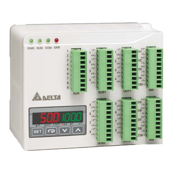
Thank you very much for choosing Delta DTE series temperature controller. Please read this instruction sheet carefully before using your
DTE to ensure proper operation. Keep this instruction sheet handy for quick reference.
Warning
DANGER! CAUTION! ELECTRIC SHOCK!
DTE is an OPEN-TYPE device and therefore should be installed in an enclosure free of airborne dust, humidity, electric shock
and vibration. The enclosure should prevent non-maintenance staff from operating the device (e.g. key or specific tools are
required for opening the enclosure) in case danger and damage on the device may occur.
1. Prevent dust or metallic debris from falling into the device and cause malfunctions. DO NOT modify or uninstall the circuit board of DTE
without being permitted. DO NOT use empty terminals.
2. Keep away from high-voltage and high-frequency environment during the installation in case of interference. Prevent using the device in
premises which contain:
(a) dust or corrosive gas; (b) high humidity and high radiation; (c) shock and vibration.
3. The power has to be switched off when wiring or changing the temperature sensor.
4. When installing the circuit board of the accessory, please make sure the power of the main unit is switched off and insert the accessory
into the correct slot on the main unit.
5. Make sure to use compensation wire which matches the thermocouple or platinum resistance when extending or connecting the
thermocouple or platinum resistance.
6. Keep the wire as short as possible when wiring a sensor to the controller. Separate the power cable and load wire in order to prevent
interference and induced noise.
7. Make sure the power cables and signal device are installed correctly before switching on the power; otherwise serious damage may
occur.
8. DO NOT touch the terminal or repair the device when the power is on; otherwise an electric shock may occur.
9. Please wait for 1 minute after the power is switched off to allow the capacitor to discharge and DO NOT touch the internal wiring within
this period.
10. DO NOT touch the internal terminal when DTE is either switched on or off in case you may damage the circuit.
11. Please place DTE with other heating objects (e.g. power supply) within proper distance while installing DTE.
Ordering Information
Series name
DTE: Delta E series temperature controller
1
Device type
0T: 4-channel TC
2
3
-
4
0P: 3-channel PT
Functions & Electrical Specifications
Power input
24 VDC, isolated switching power supply
Voltage range
90 to 110% rated voltage
Power consumption
Max. 10 W + 3 W × number of DTC2000 controllers connected in parallel (Max. 7)
Thermocouple: K, J, T, E, N, R, S, B, L, U, TXK
Input sensor
Platinum resistance: Pt100, JPt100, Cu50, Ni120
Sampling cycle
Thermocouple or platinum resistance: 1.0 second/all input
Control method
PID, PID programmable, manual, ON/OFF
Relay output: SPST, Max. 250 VAC load, 3A resistive load
Output accessories
Voltage pulse output: 12 VDC, Max. 40 mA current output
(optional)
Current output: DC 4 to 20 mA output (resistive load < 500 Ω); for OUT1 and OUT2 only
Series Temperature Controller Instruction Sheet
1: main unit
0T: 4 - channel TC
0P: 3 - channel PT
0V: 4 channels of voltage pulse output
0C: 4 channels of linear current output
0R: 4 channels of relay output
0L: 4 channels of linear voltage output
2: accessory
DS: Display and setup module
CT: 4 channels of current transformer sensors
0D: 8-channel EVENT input
1
2019/01/22
Advertisement

Related Manuals for Delta DTE10T Series


Summary of Contents for Delta DTE10T Series
- Page 1 2019/01/22 Series Temperature Controller Instruction Sheet Thank you very much for choosing Delta DTE series temperature controller. Please read this instruction sheet carefully before using your DTE to ensure proper operation. Keep this instruction sheet handy for quick reference. Warning...
- Page 2 Analog voltage output: 0 to 10 V (resistive load > 1,000 Ω); for OUT1 and OUT2 only Control output, alarm output or proportional output (proportional output is only applicable in the model with linear Output functions voltage and current output for OUT1, OUT2) Alarm modes 13 alarm modes available Communication...
- Page 3 Input The standard DTE main unit is attached with 4 channels of inputs. You can purchase additional DTE20T to expand the number of input channels. DTE supports maximum 8 channels of inputs which belong to group INA and group INB. Each group possesses 4 input channels. DTE series supports the following input sensors: Input Sensor Type Register Value...
- Page 4 When there are only 4 channels of inputs, SUB1 cannot be used for alarm output but heating/cooling control only. When there are only 4 channels of inputs, OUT2 and SUB2 cannot be set up by the user but set up automatically as "alarm output” by the controller.
- Page 5 5. Input signal error. 6. The Input low voltage (less than 4V) Synchronous Communication Protocol & Auto ID Setup This function allows the auto setup of communication protocol in extension module DTC2000 and DTC2001 following the communication protocol set in the DTE main unit. The station IDs of DTC decrease. See below for the steps. 1.
- Page 6 2. When you use INA input or INA + INB input, set up relevant parameters using the table below. INA input: OUT1 control mode 10A8H 10A9H 10AAH 10ABH OUT2 control mode 10B0H 10B1H 10B2H 10B3H Alarm 1 output mode 10C0H 10C1H 10C2H 10C3H...
- Page 7 If there is already a set value in 4824H and you would like to modify it, reset it to 0 before you set up a new value. 2. Each channel can be set up individually for specific functions. Addresses: Address for the 1998H 1999H...
- Page 8 If the “multistate” function is enabled, for example, writing in 0028H means enabling bit5 and bit3 at the same time. If there is already a set value in 4824H and you would like to modify it, reset it to 0 before you set up a new value. ...
- Page 9 Input Filter Function To avoid unstable PV display due to interferences, DTE10T offers the filter function. Instead of averaging the values, the filter function here calculate the weighted average value of the “current PV” and “previous PV”. The filter equation: PV (displayed value) = [previous PV x (filter times – 1) + current PV] / filter times The bigger the filter times, the bigger the weight of the previous PV, and the smoother the temperature display, which is a good way to suppress interferences.
- Page 10 RS-485 Communication 1. DTE supports baud rates 2,400/4,800/9,600/19,200/38,400/57,600/115,200 bps and does not support communication format 7, N, 1/8, E, 2/8, O, 2. Communication protocol = Modbus ASCII or RTU. 2. Function codes: H03 = read maximum 8 words in the register; H06 = write 1 word into the register. 3.
- Page 11 Content Explanation 1: ON-OFF (H1117) (H1217) (H1317) (H1417) (H1517) (H1617) (H1717) (H1817) 2: manual 3: PID programmable H10C0 H10C1 H10C2 H10C3 H10C4 H10C5 H10C6 H10C7 Alarm 1 output See “Alarm Output” section mode (H1118) (H1218) (H1318) (H1418) (H1518) (H1618) (H1718) (H1818) H10C4 H10C5...
- Page 12 Content Explanation Read the NO. of the current step 0 ~ 7 H1121 H1221 H1321 H1421 H1521 H1621 H1721 H1821 NO. of start pattern 0 ~ 7 H1122 H1222 H1322 H1422 H1522 H1622 H1722 H1822 NO. of start step 0 ~ 7 H1123 H1223 H1323...
- Page 13 Multi Write Command Multi Write Response Command ‘7’ ‘7’ ‘0’ ‘0’ ‘0’ ‘0’ ‘0’ ‘0’ Number of words Number of words ‘0’ ‘0’ ‘2’ ‘2’ ‘0’ LRC1 check ‘6’ Number of bytes ‘4’ LRC0 check ‘D’ ‘0’ End word 1 ‘0’...
- Page 14 = reg_crc >> 1; return(reg_crc); Software for Setting up Communication on PC: Download the free software on Delta’s website. How to Mount & DIN Rail Size Connect maximum 7 DTC2000 or DTC2001 controllers to DTE by using DIN rail.
Need help?
Do you have a question about the DTE10T Series and is the answer not in the manual?
Questions and answers