Advertisement
Series Temperature Controller Instruction Sheet
Precaution
Warning! Please comply with safety precautions in the manual. Failure to do so may cause controller or peripheral products
malfunction, or even result in serious harm such as fire, electrical injury or other damages.
DANGER! Caution! Electric Shock! Do not touch the AC terminals while the power is supplied to the controller to prevent electric
shock. Make sure power is disconnected while checking the unit inside.
This controller is an open-type temperature controller. Be sure to evaluate any dangerous application in which a serious human
injury or serious property damage may occur.
This controller is not furnished with a power switch or fuse, therefore a switch or circuit-breaker should be provided in the
application system including this unit. The switch or circuit-breaker should be nearby and easily reached by operator, and must
have the mark disconnecting means for this unit.
1. Always use recommended solder-less terminals: Fork terminal with isolation (M3 screw, width is 5.8 mm). Make sure all wires are
connected to the correct polarity of terminals.
2. Do not allow dust or foreign objects to fall inside the controller to prevent it from malfunctioning. Never modify or disassemble the
controller. Do not connect anything to the "No used" terminals.
3. To prevent interference, keep away from high voltage and high frequency when installing. Do not install and/or use the controller in
places subject to:
(a) Dust or corrosive gases and liquid; (b) High humidity and high radiation; (c) Vibration and shock;
4. Power must be off when wiring and replacing a temperature sensor.
5. Be sure to use compensating wires that match the thermocouple types when extending or connecting the thermocouple wires.
6. Please use wires with resistance when extending or connecting a platinum resistance thermometer (RTD).
7. Please keep the wire as short as possible when wiring a platinum resistance thermometer (RTD) to the controller and please route
power wires as far as possible from load wires to prevent interference and induced noise.
8. This controller is an open-type unit and must be placed in an enclosure away from high temperature, humidity, dripping water,
corrosive materials, airborne dust, and electric shock or vibration.
9. Make sure power cables and signals from instruments are all installed properly before energizing the controller, otherwise serious
damage may occur.
10. Do not touch the terminals in the controller or try to repair the controller when power is on, in order to prevent electric shock.
11. Wait at least one minute after power is disconnected to allow capacitors to discharge, and please do not touch any internal circuit
within this period.
12. When maintaining the controller, please turn off the power first and use a dry cloth to clean the surface. Do not open the enclosure or
touch the internal circuit to avoid circuit destruction or malfunction.
13. Do not use any sharp objects to press the operation buttons. It may result in button surface damage or even electrical injury when
accidentally access to internal circuit.
14. Use copper conductors only.
Product Features
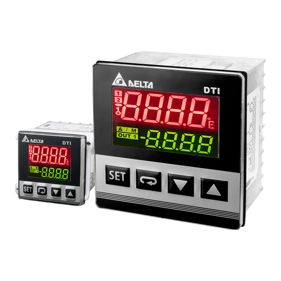
DTI series is a new temperature controller with a high cost-performance ratio. It greatly decreases development costs and time, and
improves the functions of temperature control systems. With a length of only 60mm and high resolution LCD display, it is easy for
operators to monitor the temperatures of any environment or occasion.
High resolution LCD panel: High contrast and customized display graphics for user's easy understanding.
High-speed sampling time 100ms: High-speed sampling for external temperature measurement and fast output response for
performance requirements of high-precision control.
Shortened length to 60mm: Shorten the length of the controller to reduce the installation space.
Conform with CE international safety certification
2019/08/12
1
Advertisement
Table of Contents

Related Manuals for Delta DTI Series


Summary of Contents for Delta DTI Series
- Page 1 Product Features DTI series is a new temperature controller with a high cost-performance ratio. It greatly decreases development costs and time, and improves the functions of temperature control systems. With a length of only 60mm and high resolution LCD display, it is easy for operators to monitor the temperatures of any environment or occasion.
-
Page 2: Ordering Information
: Button locking indicator Ordering Information DTI 1 2 3 4 5 6 Series DTI: Delta DTI Series Temperature Controller 4848:4848 1/16 DIN W48 × H48mm Panel Size (W×H) 9696:9696 1/4 DIN W96 × H96mm R: Relay output, 250 VAC, 3A... -
Page 3: Operation
Alarm Output Type Relay output: Max. load 250VAC, 3A resistive load Display Accuracy 0 or 1 digit to the right of the decimal point (selectable) Sampling Rate Thermocouple or platinum resistor: 0.2 sec Vibration Resistance 10 to 55 Hz, 10 m/s2 for 10 min, each in X, Y, and Z directions Shock Resistance Max. -
Page 4: Display Unit Setting
ALARM1 SET: Set up Alarm 1 mode (refer to "Alarm Outputs") ALARM1 OPTION: Set up Alarm 1 options (refer to "Alarm Outputs") ALARM1 DELAY: Set up Alarm 1 delay Parameter Settings for Regulation Mode: Factory Display Description Setting AT: Auto-tuning Switch (display when setting Ctrl = PID/RUN) P: Proportional Setting (display when setting Ctrl = PID and TUNE = AT) 30.0 I: Integral Time Setting (display when Crtl = PID;... - Page 5 K, J, T, E, N, R, S, B, L, U, TX (TXK), JP (JPT100), PT (Pt100), CU (CU50), NI (NI120) Selection for Heating/Cooling/Alarm/Dual-Loop Output Control DTI series features 1 set of Output Control (OUT1) and 1 set of Alarm Output (ALARM1), both of which are built-in. ...
-
Page 6: Control Mode Setting
Output of when in PID control mode (Ctrl = PID): Heating Cooling Heatin Coolin Set Point Set Point When the controller is in PID control and dual loop output mode, parameter sets the P value of the 2nd set of PID. The 1st set of PID is generated when TUNE = AT, but user can also manually set the PID value. -
Page 7: Tune Function
Set AT: Set parameter in Regulation Mode. The selected number of PID sets will be adjusted automatically. After that, a PID value will be created automatically and the display will automatically alter into Note: When performing AT, set up for the entire system must be completed, i.e. the input sensor must be wired and correctly set, and the output must be connected to a heater or cooler pipe. -
Page 8: Alarm Outputs
unlocked. If two entries of the password are not the same, the screen will return to the state of step 2. Cannot remember the password: Restore factory settings to release the locking. Alarm Outputs This controller features one or two alarm outputs. A total of 9 alarm settings can be made independently as shown in the table. Additional settings are provided, such as alarm delay, alarm standby, alarm output hold, and alarm reverse output, as described below: Alarm Delay Setting: Sets alarm delay time. -
Page 9: Error Code
Bit3 Bit2 Bit1 Bit0 No function Hold Alarm Reverse Alarm Standby Alarm Error code When error occurs, you can read 1000H registers via communication. Please refer RS485 section for displaying the different error reason with hexadecimal H8001~H8007 codes. ... - Page 10 Wiring Diagrams and Precautions Tighten the screw to the torque between 0.4 and 0.5N.m. To avoid signal interference, it is suggested that the power cable and the signal cable to be set separately. Please use solid wires between 14AWG/2C and 22AWG/2C. Maximum 300V and rated temperature to 105°C for input power pins. ...
Need help?
Do you have a question about the DTI Series and is the answer not in the manual?
Questions and answers