Delta DTE10T Series Instruction Sheet
Dte series temperature controller
Hide thumbs
Also See for DTE10T Series:
- Instruction sheet (14 pages) ,
- Instruction sheet (2 pages) ,
- Instruction sheet (14 pages)
Advertisement
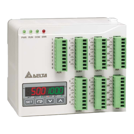
Thank you very much for choosing Delta DTE series temperature controller. Please read this instruction sheet carefully before using your DTE
to ensure proper operation. Keep this instruction sheet handy for quick reference.
Precaution
DANGER! Caution! Electric Shock!
DTE is an OPEN-TYPE device and therefore should be installed in an enclosure free of airborne dust, humidity, electric shock and vibration.
The enclosure should prevent non-maintenance staff from operating the device (e.g. key or specific tools are required for opening the
enclosure) in case danger and damage on the device may occur.
WARNING!
1. Prevent dust or metallic debris from falling into the device and cause malfunctions. DO NOT modify or uninstall the circuit board of DTE
without being permitted. DO NOT use empty terminals.
2. Keep away from high-voltage and high-frequency environment during the installation in case of interference. Prevent using the device in
premises which contain:
(a) dust or corrosive gas; (b) high humidity and high radiation; (c) shock and vibration.
3. The power has to be switched off when wiring or changing the temperature sensor.
4. When installing the circuit board of the accessory, please make sure the power of the main unit is switched off and insert the accessory
into the correct slot on the main unit.
5. Make sure to use compensation wire which matches the thermocouple or platinum resistance when extending or connecting the
thermocouple or platinum resistance.
6. Keep the wire as short as possible when wiring a sensor to the controller. Separate the power cable and load wire in order to prevent
interference and induced noise.
7. Make sure the power cables and signal device are installed correctly before switching on the power; otherwise serious damage may
occur.
8. DO NOT touch the terminal or repair the device when the power is on; otherwise an electric shock may occur.
9. Please wait for 1 minute after the power is switched off to allow the capacitor to discharge and DO NOT touch the internal wiring within
this period.
10. DO NOT touch the internal terminal when DTE is either switched on or off in case you may damage the circuit.
11. Please place DTE with other heating objects (e.g. power supply) within proper distance while installing DTE.
Ordering Information
Series name
DTE: Delta E series temperature controller
1: main unit
1
Device type
0T: 4-channel TC
2
3
-
4
0P: 3-channel PT
Series Temperature Controller
Instruction Sheet
0T: 4-channel TC
0V: 4 channels of voltage pulse output
0C: 4 channels of linear current output
0R: 4 channels of relay output
0L: 4 channels of linear voltage output
CT: 4 channels of current transformer sensors
DS: Display and setup module
- 1 -
2: accessory
0P: 3-channel PT
0D: 8-channel EVENT input
Advertisement
Table of Contents

Related Manuals for Delta DTE10T Series


Summary of Contents for Delta DTE10T Series
-
Page 1: Ordering Information
Series Temperature Controller Instruction Sheet Thank you very much for choosing Delta DTE series temperature controller. Please read this instruction sheet carefully before using your DTE to ensure proper operation. Keep this instruction sheet handy for quick reference. Precaution DANGER! Caution! Electric Shock! DTE is an OPEN-TYPE device and therefore should be installed in an enclosure free of airborne dust, humidity, electric shock and vibration. -
Page 2: Specifications
Specifications Power input 24 VDC, isolated switching power supply Voltage range 90 to 110% rated voltage Power consumption Max. 10 W + 3 W × number of DTC2000 controllers connected in parallel (Max. 7) Thermocouple: K, J, T, E, N, R, S, B, L, U, TXK Input sensor Platinum resistance: Pt100, JPt100, Cu50 Sampling cycle... - Page 3 Input The standard DTE main unit is attached with 4 channels of inputs. You can purchase additional DTE20T or DTE20P to expand the number of input channels. DTE supports maximum 8 channels of inputs which belong to group INA and group INB. Each group possesses 4 input channels.
-
Page 4: Control Output
Value = 0 Value = 1 Value = 2 Value = 3 OUT1, OUT2** Heating control Cooling control Proportional output Disable output SUB1, SUB2** Heating control Cooling control Alarm output* Disable output Table 3 When there are only 4 channels of inputs, SUB1 cannot be used for alarm output but heating/cooling control only. When there are only 4 channels of inputs, OUT2 and SUB2 cannot be set up by the user but set up automatically as "alarm output”... -
Page 5: Led Display
LED Display PWR: On DTE is powered. RUN: On Any of the channel is executing. COM: Flashing Communication in progress ERR: Indicating errors (red) ERR LED is on indicates one of the following errors occur, and the output has to be disabled. 1. -
Page 6: Event Input
INA + INB input: INA+INB OUT1 control mode 10A8H 10A9H 10AAH 10ABH 10ACH 10ADH 10AEH 10AFH Alarm 1 output mode 10C0H 10C1H 10C2H 10C3H 10C4H 10C5H 10C6H 10C7H Upper bound of Alarm 1 output 1080H 1081H 1082H 1083H 1084H 1085H 1086H 1087H Lower bound of Alarm 1 output... -
Page 7: Delayed Alarm
How to Operate 1. Enable the slope function: Write 1234H into the address 47F1H and then 0020H into address 4824H. bits in 4824H Bit7 Bit6 Bit5 Bit4 Bit3 Bit2 Bit1 Bit0 Hot runner Flag Slope control Latch EVENT control Notes: ... -
Page 8: Output Limits
Output Limits Function The output is limited between the maximum and minimum percentages. How to Operate Set up relevant parameters using the table below. Max. output (%) 1980H 1981H 1982H 1983H 1984H 1985H 1986H 1987H Min. output (%) 1988H 1989H 198AH... - Page 9 If there is already a set value in 4824H and you would like to modify it, reset it to 0 before you set up a new value. 2. Set up relevant parameters using the table below. Temp. bound (unit: 0.1°) 1960H 1961H 1962H...
- Page 10 Content Explanation H1070 H1071 H1072 H1073 H1074 H1075 H1076 H1077 Read/write output 1 value Unit: 0.1 % (H110E) (H120E) (H130E) (H140E) (H150E) (H160E) (H170E) (H180E) H1078 H1079 H107A H107B H107C H107D H107E H107F Read/write output 2 value Unit: 0.1 % (H110F) (H120F) (H130F)
- Page 11 Communication Parameter Setting Content Baudrate 2,400bps 4,800bps 9,600bps 19,200bps 38,400bps 57,600bps 115,200bps Parity bit None (N) Even (E) Odd (O) Table 4 Error Codes The error codes can be read from address H1000 ~ H1007. When the input operation is in normal status, H1000 ~ H1007 are for input values. When input error occurs (except for stable status and input exceeding the range), DTE will read error codes in H8001 ~ H8002.
- Page 12 (j = 0; j < 8; j++) { if (reg_crc & 0x01) reg_crc = (reg_crc >> 1) ^ 0xA001; else reg_crc = reg_crc >> 1; return(reg_crc); Software for Setting up Communication on PC: Download the free software on Delta’s website. - 12 -...
- Page 13 How to Mount & DIN Rail Size Connect maximum 7 DTC2000 or DTC2001 controllers to DTE by using DIN rail. - 13 -...
Need help?
Do you have a question about the DTE10T Series and is the answer not in the manual?
Questions and answers