Delta A Series (DTA) - Temperature Controller Instructions
Also See for A Series:
- Instruction sheet (13 pages)
Advertisement
Table of Contents
Contents
Delta A Series (DTA) - Temperature Controller Instructions
Precaution

Electric Shock!
- Do not touch the AC terminals while the power is supplied to the controller to prevent an electric shock.
- Make sure power is disconnected while checking the unit inside.

This controller is an open-type temperature controller. Make sure to evaluate any dangerous application in which a serious human injury or serious property damage may occur.
- Do not allow dust or foreign objects to fall inside the controller to prevent it from malfunctioning.
- Never modify or disassemble the controller.
- Do not connect anything to the "No used" terminals.
- Must turn power off when wiring and changing a temperature sensor.
- This controller is an open-type unit and must be placed in an enclosure away from high temperature, humidity, dripping water, corrosive materials, airborne dust and electric shock or vibration.
- Wait at least one minute after power is disconnected to allow capacitors to discharge, and please do not touch any internal circuit within this period.
Ordering Information
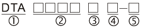
| 1 | Series | DTA: Delta A Series Temperature Controller |
| 2 | Panel Size | 4848, 4896, 9648, 7272, 9696 |
| 3 | Output Selection | R: Relay output, SPDT (SPST: 1/16 DIN size), 250VAC, 5A V: Voltage Pulse output, 14V+10% ~ -20% (Max. 40mA) C: Current output, 4~20mA |
| 4 | Communication (Optional) | 0: No interface 1: RS-485 |
| 5 | Current Transformer (Optional) | None: No CT function (Current transformer is not provided) T: Current transformer is provided (only DTA7272 series support) |
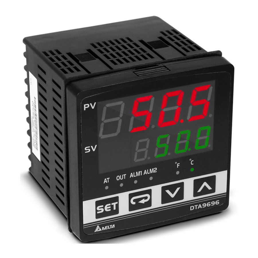
Display, LED & Pushbuttons
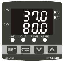
- PV Display : to display the process value or parameter type.
- SV Display : to display set point, manipulated variable or set value of the parameter.
- AT : flashes when the Auto-tuning operation is ON.
- OUT : lights when the output is ON.
- ALM1 / ALM2 : lights when Alarm 1 or Alarm 2 output is ON.
![]() : Function key. Select the desired function mode and confirm a setting value.
: Function key. Select the desired function mode and confirm a setting value.![]() : Mode key. Press this key to set parameters within each function mode.
: Mode key. Press this key to set parameters within each function mode.![]() : Up key. Press this key to increase values displayed on the SV display. Hold down this key to speed up the
: Up key. Press this key to increase values displayed on the SV display. Hold down this key to speed up the![]() : Down key. Press this key to decrease values displayed on the SV display. Hold down this key to speed up the decrements
: Down key. Press this key to decrease values displayed on the SV display. Hold down this key to speed up the decrements
 : Function key. Select the desired function mode and confirm a setting value.
 : Mode key. Press this key to set parameters within each function mode.
 : Up key. Press this key to increase values displayed on the SV display. Hold down this key to speed up the
 : Down key. Press this key to decrease values displayed on the SV display. Hold down this key to speed up the decrements
Specifications
| Input voltage | 100 ~ 240VAC, 50/60Hz |
| Display method | 7-segment digit LED Display Process value (PV): Red, Set point (SV): Green |
| Sensor type | Thermocouple: K, J, T, E, N, R, S, B, U, L, Txk |
| 3-wire Platinum RTD: Pt100, JPt100 Copper resistor: Cu50 | |
| Control mode | PID, ON/OFF control or Manual tuning |
| Display accuracy | 0.1% of measuring range |
| Sampling rate | 500 msec/per scan |
| Ambient temperature | 0o C ~ 50o C |
| Relative humidity | 35% ~ 80% (non-condensing) |
Operation

- Operation Mode: Perform per the settings of related control parameters
| LED Display | Explanation | Default |
 | RUN/STOP: Control setting begins. Run (  ) or Stop ( ) or Stop (  ) mode on the SV display. ) mode on the SV display. | RUN |
 | ALARM1 HIGH: Upper-limit alarm 1 | 4.0 oC |
 | ALARM1 LOW: Lower-limit alarm 1 | 4.0 oC |
 | ALARM2 HIGH: Upper-limit alarm 2 | 4.0 oC |
 | ALARM2 LOW: Lower-limit alarm 2 | 4.0 oC |
 | Setting lock: Lock 1 (  ), Lock 2 ( ), Lock 2 (  ) or OFF ( ) or OFF (  ) on the SV display. Lock 1 mode can lock all settings and Lock 2 mode only can lock others than SV value. When OFF mode is selected, the Lock function will be OFF. ) on the SV display. Lock 1 mode can lock all settings and Lock 2 mode only can lock others than SV value. When OFF mode is selected, the Lock function will be OFF.If you press  and and  key simultaneously, the "Lock" status can be released and the controller will be back to the previous display. key simultaneously, the "Lock" status can be released and the controller will be back to the previous display. | OFF |
 | OUT: Output value display and output value adjustment in manual tuning control | 0 |
 | CT: In case of using an external current transformer (CT), the controller displays the current value being measured by CT, if the control output is ON | Read only |
- Regulation Mode: Set the control parameters
| LED Display | Explanation | Default |
 | AT: Auto-tuning setting. When AT key is set to ON (  ). ). | OFF |
 | P: Proportional Band (PID control) | 47.6 |
 | I: Integral Time (PID control) | 260 |
 | D: Derivative Time (PID control) | 41 |
 | PdoF: Offset output when P or PD control function is ON. | 0 |
 | ioF: Default value of integral volume when PID control function is ON and integral time constant is not equal to 0(zero). | 0 |
 | HTS: Set Heating hysteresis when ON/OFF control function is ON. | 0 |
 | CTS: Set Cooling hysteresis when ON/OFF control function is ON. | 0 |
 | HTPD: PID heating control cycle setting (PID control) | C, V: 4sec |
 | CLPD: PID cooling control cycle setting (PID control) | R: 20sec |
 | TPOF: Regulate temperature deviation value | 0 |
 | TPGN: Regulate temperature gain value | 0 |
 | CRHI: Regulate 20mA output deviation value | 0 |
 | CRLO: Regulate 4mA output deviation value | 0 |
- Initial Setting Mode: Initial settings of the controller and communication parameters
| LED Display | Explanation | Default |
 | INPUT: Select input temperature sensor type | PT2 |
 | UNIT: Temperature display unit, C (  ) and F ( ) and F (  ) ) | oC |
 | T-HIGH: Upper limit for temperature range | 500.0 |
 | T-LOW: Lower limit for temperature range | -20.0 |
 | CONTROL: Control method setting on the SV display: PID (  ), ON/OFF control ( ), ON/OFF control (  ), or manual tuning ( ), or manual tuning (  ) ) | PID |
 | SWITCH: Select Heating (  ) or Cooling ( ) or Cooling (  ) action ) action | HEAT |
 | AL1 SET: Alarm 1 setting | 0 |
 | AL2 SET: Alarm 2 setting | 0 |
 | C SELECT : ASCII, RTU communication formats selection | ASCII |
 | C WE: Write-in function disable/enable | OFF |
 | C NO: Address setting | 1 |
 | BPS: Baud rate setting | 9,600 |
 | LENGTH: Data length setting | 7 |
 | PARITY: Parity bit setting | E |
 | STOP BIT: Stop bit setting | 1 |
Temperature Sensor Type & Temperature Range
| Sensor type | Display | Range | Sensor type | Display | Range |
| Pt100 |  | 0.0 ~ 100.0°C | E |  | 0 ~ 600°C |
| Pt100 |  | -20.0 ~ 500.0°C | T |  | -20.0 ~ 400.0°C |
| Pt100 |  | -200 ~ 600°C | T |  | -200 ~ 400°C |
| JPt100 |  | 0.0 ~ 100.0°C | J |  | -20.0 ~ 400.0°C |
| JPt100 |  | -20.0 ~ 400.0°C | J |  | -100 ~ 850°C |
| Cu50 |  | -50.0 ~ 150.0°C | K |  | -20.0 ~ 500.0°C |
| Cu50 |  | -50 ~ 150°C | K |  | -200 ~ 1300°C |
| B |  | 100 ~ 1800°C | L |  | -200 ~ 850°C |
| S |  | 0 ~ 1,700°C | U |  | -200 ~ 500°C |
| R |  | 0 ~ 1,700°C | Txk |  | -200 ~ 800°C |
| N |  | -200 ~ 1,300°C |
Alarm Outputs
| Set Value | Alarm Type |
| 0 | Alarm function disabled |
| 1 | Deviation upper- and lower-limit: This alarm output operates when PV value is higher than the setting value SV+(AL-H) or lower than the setting value SV-(AL-L). |
| 2 | Deviation upper-limit: This alarm output operates when PV value is higher than the setting value SV+(AL-H). |
| 3 | Deviation lower-limit: This alarm output operates when PV value is lower than the setting value SV-(AL-L). |
| 4 | Reverse deviation upper- and lower-limit: This alarm output operates when PV value is in the range of the setting value SV+(AL-H) and SV-(AL-L). |
| 5 | Absolute value upper- and lower-limit: This alarm output operates when PV value is higher than the setting value AL-H or lower than setting value AL-L. |
| 6 | Absolute value upper-limit: This alarm output operates when PV value is higher than the setting value AL-H. |
| 7 | Absolute value lower-limit: This alarm output operates when PV value is lower than the setting value AL-L. |
| 8 | Deviation upper- and lower-limit with standby sequence: This alarm output operates when PV value reaches set value (SV value) and the value is higher than the setting value SV+(AL-H) or lower than the setting value SV-(AL-L). |
| 9 | Deviation upper-limit with standby sequence: This alarm output operates when PV value reaches set value (SV value) and the reached value is higher than the setting value SV+(AL-H). |
| 10 | Deviation lower-limit with standby sequence: This alarm output operates when PV value reaches the set value (SV value) and the reached value is lower than the setting value SV-(AL-L). |
| 11 | Hysteresis upper limit alarm output: this alarm output operates if PV value is higher than the setting value SV+(AL-H). This alarm output is OFF when PV value is lower than the setting value SV+(AL-L). |
| 12 | Hysteresis lower limit alarm output: this alarm output operates if PV value is lower than the setting value SV-(AL-H). This alarm output is OFF when PV value is higher than the setting value SV-(AL-L). |
| 13 | CT alarm output: This alarm operates when the current measured by transformer (CT) is lower than AL-L or higher than AL-H (This alarm output is available only for the controller with current transformer). You can set current alarm range between 0.5A ~ 30A, display resolution is 0.1A and measure accuracy is +/- 0.5A. |
Communication Parameters List
- Communication protocol: Modbus (ASCII), 2400 ~ 38400bps
- Function code: 03H to read the contents of register (Max. 3 words); 06H to write 1 (one) word into register.
| Address | Content | Explanation |
| 4700H (R) | Process value (PV) | Measuring unit is 0.1 oC or oF |
| 4701H | Set point (SV) | Unit is 0.1, oC or oF |
| 4702H | Upper-limit alarm 1 | |
| 4703H | Lower-limit alarm 1 | |
| 4704H | Upper-limit alarm 2 | |
| 4705H | Lower-limit alarm 2 | |
| 4706H | Upper-limit of temperature range | The data content should not be higher than the temperature range. |
| 4707H | Lower-limit of temperature range | The data content should not be lower than the temperature range. |
| 4708H | PB Proportional band | 0.1 ~ 999.9, unit is 0.1 |
| 4709H | Ti Integral time | 0 ~ 9,999 |
| 470AH | Td Derivative time | 0 ~ 9,999 |
| 4711H | Control method | 0: PID, 1: ON/OFF, 2: manual tuning |
| 4714H | Temperature regulation value | -999 ~ 999, unit: 0.1 |
| 4718H | Heating/Cooling control Selection | Heating: 0 (default), Cooling: 1 |
| 4719H | Control Run/Stop setting | Run: 1 (default), Stop: 0 |
| 4729H | AT setting | Off: 0 (default), On: 1 |
| 4733H | CT monitor value | Unit is 0.1A |

Documents / ResourcesDownload manual
Here you can download full pdf version of manual, it may contain additional safety instructions, warranty information, FCC rules, etc.
Download Delta A Series (DTA) - Temperature Controller Instructions
Advertisement


Need help?
Do you have a question about the A Series and is the answer not in the manual?
Questions and answers