
Subscribe to Our Youtube Channel
Related Manuals for Security Labs SLD 244


Summary of Contents for Security Labs SLD 244
-
Page 1: Digital Video Recorder
Four Channel Multiplexed Digital Video Recorder Owner’s Manual Customer Support 1-800-774-0284... -
Page 2: Table Of Contents
Content 1. SAFETY PRECAUTIONS..............2 2. INTRODUCTION................3 2.1 Product Introduction ..............3 2.2 Application ................4 3. FEATURES..................4 4. PACKING LIST ................. 5 5. INSTALLATION ................6 6. NAME and FUNCTION of EACH PART ............7 6.1 Front Panel ................7 6.2 Rear Panel ................. -
Page 3: Safety Precautions
9.2 Connecting Network DVR ............40 9.2.1 Online using Intranet or Fixed IP ..........41 9.2.2 Online using ADSL (PPPoE) Router ........41 9.2.3 Online using DDNS Server ............. 41 9.2.4 Online Connection ..............41 9.2.4.1 Install ActiveX ..............42 9.3 Main Display ................ -
Page 4: Introduction
CAUTION RISK OF ELECTRIC SHOCK. DO NOT OPEN! CAUTION : TO REDUCE THE RISK OF ELECTRICAL SHOCK, DO NOT OPEN COVERS (OR BACK). NO USER SERVICEABLE PARTS INSIDE. REFER SERVICING TO QUALIFIED SERVICE PERSONNEL. Please read the Safety Precaution Guide through carefully before operating this product. -
Page 5: Application
environments, industry surveillance, school, or any security application. The 4-channel M-JPEG Network (optional) digital video recording, enables monitoring through the internet or local area network (LAN). Video can be searched by time and event. The administrator can setup an administrator password to prevent any user from randomly changing the setup. -
Page 6: Packing List
?? High efficient event recording, saving storage capacity. Motion detection function enables recording only when system detects motion, and increases the amount of time available for recording. ?? Easy access to the desired record. Time & date search supports instant retrieval of video. Alarm event search Allows the user to retrieve events created by motion detection or an alarm input. -
Page 7: Installation
Power Cord CD-Viewing and configuration software Quick Start Guide 5. INSTALLATION Rear Panel Connections Connect your system components to the DVR according to the following illustration (network is an optional feature and may not be on your DVR):... -
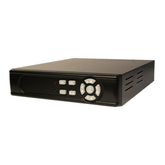
Page 8: Name And Function Of Each Part
6. Connections & Panel Buttons 6.1 Front Panel : Record LED indicator. : Rewind button. : Fast forward button. : Left direction button / CH 2 screen display / Number button 2... - Page 9 : Up direction button / CH 1 screen display / Number button 1 : Right direction button / Enter Selection/ CH 4 screen display / Number button 4 : Enter / Exit Menu : Down direction button / CH 3 screen display / Number button 3 : Record / Stop button (10) : Play / Pause button...
-
Page 10: Rear Panel
6.2 Rear Panel RJ45: Internet connection terminal (optional). USB: Connect to external USB storage device (Plug and Play). Video Input [VIDEO IN]: Connect to cameras. Video Output [VIDEO OUT]: Connect to the monitor. DC 12V [Power Input terminal]: power socket. -
Page 11: Operating Procedure
7. OPERATING PROCEDURE 7.1 Power On After power on, DVR will auto-detect its peripherals (self-testing, auto detects the hard disk, and the optional network connection. The system will detect the video input and judge whether the video system is NTSC or PAL. -
Page 13: Record Mode
7.3 Record Mode Note:CH1: A square block next to the CH number indicates it is recording that channel EACH: Record Type QUAD: Record Type (T): TIMER RECORD (A): MOTION RECORD (M): MIX RECORD (? ): Currently recording. VIDEO LOSS: The DVR does not detect video on that CH. CAMERA1: Title for CH 1. -
Page 14: Playback Mode
7.4 Playback Mode TIME SEARCH 03/11/27 18:20:42 - 03/11/27 19:32:32 >01 TIME 2003/11/27 18:20:42 02 TIME 2003/11/27 16:43:56 03 TIME 2003/11/27 15:07:11 ) MOVE ( )CHANGE (PLAY)PLAY (MENU) EXIT (FF)SELECT EVENT OR TIME >01 TIME Total 7 >07 1. First press the« STOP»button to stop recording, then press the PLAY»button to enter the search display. -
Page 15: System Setup
8. SYSTEM SETUP 8.1 Menu (3) > SYSTEM SETUP CAMERA SETUP RECORD SETUP BUZZER SETUP EVENT LIST USB DEVICE SETTING HARD DRIVE SETUP (4) PRESS ( ), THEN ( PRESS (MENU) TO EXIT (1) MAIN MENU: Root directory of the setup menu (2) Sub-menu Indictors: : First Menu Layer (Main Menu) ¦... -
Page 16: System Setup
8.2 System Setup SYSTEM SETUP > TIME SETUP PASSWORD SETUP LOARD DEFAULT LANGUAGE SETUP ENGLISH VERSION V1.4 PRESS( ), THEN ( PRESS (MENU) TO EXIT 1. The cursor (>) position indicates the current function selected. 2. Press the« ? » and« ? » button to move the cursor. 3. -
Page 17: Time Setup
8.2.1 Time Setup TIME SETUP 2005/01/11 17: 23: 06 PRESS ( ), THEN ( PRESS (MENU) TO EXIT 1. The cursor (^) position indicates the current time and date selected. 2. Use the« ? » or« ? » button to move the cursor. 3. -
Page 18: Password Setup
8.2.2 Password Setup PASSWORD SETUP > PASSWORD CHANGE MENU PASSWORD STOP REC PASSWORD PRESS ( ), THEN ( PRESS (MENU) TO EXIT Cursor (>) position indicates the current function selected. Use the« ? » and« ? » button to move the cursor to the desired item . Use the«... -
Page 19: Change Password
will be shown on the display. To disable the message, press button: QUAD, CH1, CH2, CH3, or CH4. 8.2.2.1 Change Password CURRENT PASSWORD _ _ _ _ _ _ PASSWORD _ _ _ _ _ _ CONFIRM PASSWORD _ _ _ _ _ _ PRESS (MENU) TO EXIT 1. -
Page 20: Load Default
system returns to “Password setup” selection. ? All buttons may be used as a password during password setup, except for the MENU button. 8.2.3 Load Default LOAD DEFAULT PRESS ( ) TO RESET PRESS (MENU) TO EXIT 1. Press the« ? » button to show the display above. 2. -
Page 21: Camera Setup
8.3 Camera Setup CAMERA SETUP > CAMERA ENABLE 1234 CAMERA TITLE ---- CAMERA SETTING CH1 TITLE CAMERA1 CH2 TITLE CAMERA2 CH3 TITLE CAMERA3 CH4 TITLE CAMERA4 PRESS ( ), THEN ( PRESS (MENU) TO EXIT Cursor (>) position indicates the current function selected. Press the«... - Page 22 standard camera setup, etc. Press the« ? » or« ? » button to move up and down and« ? » button to change the camera view combination (select to view the desired channel). 1) Select (- - - -), all cameras are disabled (no image display). 2) Select (1 2 3 4), all cameras are operational (quad image display).
-
Page 23: Camera Setup
8.3.1 Camera Setup CAMERA SETTING > CAMERA SELECT RECORD ENABLE MOTION DETECTION MOTION SENSITIVITY CONTRAST BRIGHTNESS PRESS ( ), THEN ( PRESS (MENU) TO EXIT Cursor (>) position indicates the current function selected. Press the« ? » and« ? » button to move the cursor to the desired item. Press the«... - Page 24 MOTION SENSITIVITY: Press the « ? » button to setup the motion sensitivity rate (5 sensitivity rate values, 01 most sensitive). HUE: Press the« ENTER» button to adjust the color of cameras (15 color adjustment values, default value: 08). 10. CONTRAST: Press the« ? » button to adjust the camera contrast (15 contrast adjustment values, default value: 08).
-
Page 25: Record Setup
8.4 Record Setup RECORD SETUP > RECORD TYPE EACH VIDEO QUALITY NORMAL TIME RECORD FRAMERATE MOTION RECORD FRAMERATE MOTION REC TIME RECORD MODE PRESS ( ), THEN ( PRESS (MENU) TO EXIT Cursor (>) position indicates the current function selected. Use the«... - Page 26 TIME RECORD FRAMERATE: Press the« ? » button to setup the recording speed when “T” mode is setup under schedule record mode. MOTION RECORD FRAMERATE: Press the« ? » button to setup different recording speeds per channel, suitable when the recording speed under schedule record mode is setup to “M”...
-
Page 27: Record Mode
8.4.1 RECORD MODE RECORD MODE T: TIME A: MOTION M: TIME+MOTION < M A T T T T T T T T T T T T T T T T T T T T- T > 21 24 PRESS ( ), THEN ( PRESS (MENU) TO EXIT The cursor (V) position indicates the current function selected. -
Page 29: Buzzer Setup
8.5 Buzzer Setup BUZZER SETUP > MOTION ALERT VIDEO LOSS ALERT HDD FULL ALERT BUZZER TIME PRESS ( ), THEN ( PRESS (MENU) TO EXIT Cursor (>) position indicates the current selected position. Press the« ? » and« ? » button to move the cursor to the desired item (time). Press the«... - Page 30 VIDEO LOSS ALERT: Press the« ? » button to setup “ON” or “OFF”, whether to trigger the alarm when video loss has been detected (this setup is only active when the system is under record or live status). HDD FULL ALERT: Press the« ? »button to setup “ON” or “OFF”, whether to trigger the alarm when hard disk is full (this setup is only active when the system is in the record mode).
-
Page 31: Event List
8.6 Event List EVENT LIST > TIME SEARCH EVENT SEARCH PRESS ( ), THEN ( PRESS (MENU) TO EXIT The cursor ( ) position indicates the current function selected. > Press the« ?» and« ?» button to move the cursor to the desired item. Press the«... -
Page 32: Time Search
8.6.1 TIME SEARCH TIME SEARCH 05/01/13 19 27 16 BEGIN TIME 05/01/13 19 27 16 END TIME 05/01/15 15 00 06 )MOVE ( )CHANGE (MENU)EXIT (PLAY)PLAY TIME SEARCH: Displays system recording time (begin and end). Press the« ? » and« ? » button to select the desired time and date. Press the«... -
Page 33: Event Search
8.6.2 EVENT SEARCH EVENT SEARCH BEGIN 05/01/15 15 00 01 05/01/15 15 00 06 > 01 MOTION 2005/01/15 15 00 01 02 MIX 2005/01/15 14 00 01 03 TIME 2005/01/15 13 00 01 04 MOTION 2005/01/15 12 00 01 ) MOVE ( ) CHANGE (MENU) EXIT (PLAY) PLAY EVENT SEARCH: Displays all recording events, every page consists of 7... -
Page 34: Usb Setup
8.7 USB SETUP ¦¦ USB SETUP > COPY FORMAT/ERASE TOTAL CAPACITY 512MB REMAINING CAPACITY 100MB PRESS ( ) THEN( PRESS (MENU) TO EXIT 1. The cursor ( ) position indicates the current function selected. > 2. Press the« ? » and« ? » button to select the desired event to playback. 3. -
Page 35: Time Setup
been detected. ? When the message “USB STORAGE NOT SUPPORT” appears indicates that the USB is not supported by the DVR. ? When applying COPY function for the first time, please use theFORMAT/ERASE function and initialize the USB storage device. ? Please do not use your PC to format the USB storage device as data loss may occur. -
Page 36: Copy
function. ? When the message“TIME INPUT ERROR” appears it indicates that the time entered by the user is incorrect. The system will auto return to the “USB SETUP” menu selection. 8.7.1.1 COPY (1) COPY : 10MB (2) ESTIMATE TIME : 2 Minute (3) START COPY (4) CAPACITY IS NOT ENOUGH (5) 10% COPIED... -
Page 37: Hard Drive Setup
( 6) Press the« ? » button to copy. ( 7) Press the« MENU» button to exit COPY selection. 8.8 Hard Drive Setup HDD DRIVE SETUP > DISK FULL OVERWRITE HDD SIZE 120103MB HDD USED 120103MB 100% HDD FORMAT PRESS( )THEN( PRESS(MENU)TO EXIT Cursor (... -
Page 38: Format/ Erase
Press the« MENU» button to exit “HARD DRIVE SETUP” selection. 5. “HDD DRIVE SETUP”is located on the second menu layer. Under this menu layer, the user may setup to “OVERWRITE” or “STOP”. When the item “OVERWRITE” has been selected, press the« ? » button to enable overwrite when the HDD is full (2 options: OVERWRITE or STOP). -
Page 39: Network Remote Control (Optional)
When proceeding with the “FORMAT/ ERASE” function, the above display will be shown. When the password entered is correct, the screen will display the message “PASSWORD CORRECT”, “HDD FORMATED” (flashes 3 times). This indicates hard disk format is successful. When the password entered is incorrect, the screen will display “PASSWORD INCORRECT”... - Page 40 Online with DHCP Server...
-
Page 41: Online Without Dhcp Server
9.1.2 Online without DHCP Server 1. Use IPEdit.exe to find the installed Network DVR. 2. The Internet DVR, without the IP allocated by DHCP, will have a default IP Address of 169.254.1.13. 3. Select this Internet DVR on Camera List Window. 4. -
Page 42: Online Using Intranet Or Fixed Ip
9.2.1 Online using Intranet or Fixed IP Setup similar to “9.1 Network DVR Setup” . 9.2.2 Online using ADSL (PPPoE) Router Setup similar to “9.4.3.3 Connect to ADSL by PPPoE mode”. 9.2.3 Online using DDNS Server The DDNS service provides the dynamic IP to users to gain access to resources connected to the Internet via a cable or DSL connection. -
Page 43: Install Activex
9.2.4.1 Install ActiveX Before entering remote connection, please install ActiveX and check your browser setup by following the procedures below: a. Open Internet Explorer under “Tools”, select “Internet Options”. Tools ? Internet Options b. Select “Security”, and then press “Custom Level”. Security ->... - Page 44 Start-up ActiveX Control...
- Page 45 The message below will be shown when first time installing ActiveX Mode. Please, select “Yes” to accept installation. Download ActiveX Control Live view will be displayed when installation is successful. Live display under ActiveX mode...
-
Page 46: Main Display
9.3 Main Display Remote control DVR - Main Menu Live Display DVR Control Button Video Setup Configuration: Enter detail setup Recording: Displays recording setup menu (for video recording). Snapshot: Pop-up window displays live images, right mouse click to save. Note! To view complete interface, PC resolution must be adjusted to 1024*768. 9.3.1 Live Display View/ Make changes on image display Rotate/ Make changes on image direction... -
Page 47: View
9.3.2 View Two types of display method: a. Resizable: Adjustable image size. b. Actual size: The actual image size. 9.3.3 Rotate Four types of rotate settings: a. Rotate 0: Default state b. Rotate 180: Rotate the image by 180 degrees. c. -
Page 48: Save Current Picture
avi file is stored per second. Enter “50”, then 5 avi files are stored in 5 seconds). Size: Image storage according to “size”. Frame Rate: Image storage according to “frame rate”. Time: Image storage according to “time”. Maximum Number of Frame in Each File: Image storage according to “maximum frame”. Save Path: Image storage according to “Save Path”. -
Page 49: Quality Setting
9.3.7 Quality Setting Network DVR provides 5 image quality settings. The user can select the quality setting from the “Quality” list box. Highest High Medium Lowest... -
Page 50: Resolution Setting
9.3.8 Resolution Setting Network DVR provides six resolution settings. The user can select the quality setting from the “Resolution” list box. 176x144 160x120 320x240 352x288 640x480 704x576 Note! The device supports auto video system detection (NTSC/ PAL). 9.3.9 Advance Settings Network DVR provides the advanced settings for the following: Brightness Contrast... -
Page 51: User Setting
Reboot DVR: The system need 20 seconds to reboot the DVR (Rebooting does not effect the recording function). FirmWare update (Please refer to 6.7). ReStore Factory Default 9.4.2 User Setting User Authorization Setting Add User or Change Password Delete User Account Current Users User Setting Display 9.4.2.1 User Authorization Setting... -
Page 52: New User/ Change Password
9.4.2.2 New user/ Change Password Enter a new user name and password information to create a new user account, or enter an existing user account, then set a new password to replace the old password, and select “OK” to create the account or change password. After selecting “OK” button, the “Current User List”... -
Page 53: Dhcp
9.4.3.2 DHCP The “DHCP” is automatically set as the default network setting of the Network DVR. When a Network DVR is connected into the LAN, it will issue DHCP packets to request an IP address that is dynamically assigned by the DHCP server. If it is unable to get a DHCP address on a limited tries, the Network DVR will assign a default IP address such as “169.254.1.13”. -
Page 54: Ddns Setting
1. Power off Network DVR. 2. Connect Network DVR directly to the ADSL modem (using RJ-45 Ethernet port). 3. Power-up Network DVR. 4. Network DVR start dialing. 5. Once connected, mail the IP address information to the preset e-mail address. 6. - Page 55 To setup follow the steps below: Register at DDNS Server: http://www.dyndns.org. Apply domain name. Click the “Enable” button. Enter “UserName” and “Password” with “DomainName”. DDNS Setting After registering the domain name, please enter the information supplied by the administrator to the Network DVR DDNS Account Setting. Select “Enable” button to start-up DDNS server, and press “Submit”...
-
Page 56: Firmware Update
9.4.5 Firmware Update When new firmware (bin file) is supplied, you may update the new version firmware (bin file) to your PC by following the procedures below: Select the Firmware to be Updated Uploading the Selected Firmware Press “Upload” button to display the message below, and follow the instruction to make the necessary setup. - Page 57 Press “here” button (1) to update Firmware. Press “here” button (2) to delete the file. The message below displays the writing progress of the firmware update. When Firmware update is completed, it will show 100%, and a message “Click here to reboot DVR browser”...
-
Page 58: Hdd Player Software Description
10. HDD Player Software Description PC Player Software System Requirement ? OS (Operating System) Windows XP or later. Use your PC to install DirectX (version DirectX 7.0 or above). Using remote control software, please setup the resolution to 1024x768 or above. Hardware Requirement ? CPU 1.0 GHz or higher. - Page 59 3. Software Playback Interface Description A. User Interface System Status Figure 1 When the system detects stored video (HDD), the above graphic (Figure 1) will be shown. The user may operate the function buttons to make necessary playback adjustment or store recordings onto the PC.
- Page 60 Fast Rewind Rewind Pause Playback Forward Fast Forward Quad split screen display CH1 Full Screen Display CH2 Full Screen Display CH3 Full Screen Display CH4 Full Screen Display Click “Pause” button first before clicking “ button to capture images as ”...
- Page 61 Figure 2 Figure 3...
- Page 62 Figure 4 Figure 5...
- Page 63 B. Parameter Setup Click “Standard Setup” button to show the graphic display below (Figure 6). User may use “Change” button to setup MYS and JPEG file storage directory: Figure 6...
- Page 64 12. SPECIFICATIONS Format NTSC/EIA or PAL/CCIR Compression M-JPEG Video Input 4CH, BNC Output 1 x BNC Resolution 720 x 480 (NTSC), 720 x 576 (PAL) Frame Rate Max. 120/100 fps (NTSC/PAL) Display Division Single, Quad Resolution Max. 640 x 224 (NTSC), 640 x 272 (PAL) Frame Rate Max.
- Page 65 MEMO Customer Support 1-800-774-0284...
Need help?
Do you have a question about the SLD 244 and is the answer not in the manual?
Questions and answers