Table of Contents
Advertisement
Quick Links
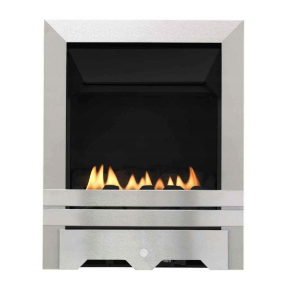
MULTIFLUE GAS FIRE
RANGE
BLENHEIM STYLE
ELEGANCE
LULWORTH
INSTALLATION AND USER
INSTRUCTIONS
All instructions must be handed to user for safekeeping
Revision C - 10/08
Country(s) of destination - GB/IE
Focal Point Fires plc, Christchurch, Dorset BH23 2BT
Tel: 01202 499330
Fax: 01202 499326
www.focalpointfires.co.uk
e-mail: sales@focalpointfires.co.uk
Advertisement
Table of Contents


Need help?
Do you have a question about the BLENHEIM STYLE and is the answer not in the manual?
Questions and answers