Table of Contents
Advertisement
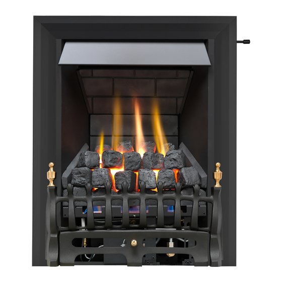
MULTIFLUE G G AS F F IRE
RANGE
BLENHEIM S S TYLE
ELEGANCE
LULWORTH
INSTALLATION A A ND U U SER
INSTRUCTIONS
All i i nstructions m m ust b b e h h anded t t o u u ser f f or s s afekeeping
Revision A - 05/04
Country(s) of destination - GB/IE
Focal Point Fires plc, Christchurch, Dorset BH23 2BT
Tel: 01202 499330
Fax: 01202 499326
www.focalpoint.co.uk
e-mail: sales@focalpointfires.co.uk
Advertisement
Table of Contents
Troubleshooting

Related Manuals for FocalPoint MULTIFLUE GAS FIRE RANGE


Summary of Contents for FocalPoint MULTIFLUE GAS FIRE RANGE
- Page 1 All i i nstructions m m ust b b e h h anded t t o u u ser f f or s s afekeeping Revision A - 05/04 Country(s) of destination - GB/IE Focal Point Fires plc, Christchurch, Dorset BH23 2BT Tel: 01202 499330 Fax: 01202 499326 www.focalpoint.co.uk e-mail: sales@focalpointfires.co.uk...
- Page 2 INST T ALLAT T ION I I NST T RUCT T IONS Blenheim Style Elegance Lulworth P P relim m in n ary N N otes B B efore I I n n stallation n This appliance is an Inset Live Fuel Effect appliance that provides radiant warmth utilising the latest type burner technology.
-
Page 3: Table Of Contents
Sec c tion Contents s Pag g e N N o. Sec c tion Contents s Pag g e N N o. Important Notes Cable Fixing Appliance Data Fitting the Burner Tray Installation Requirements Fuel Bed Layout (coal versions) Site Requirements Fuel Bed Layout (pebble versions) Debris Collection Space 10.0... -
Page 4: Appliance D D Ata
APPLIANCE D D ATA Gas Group G20 Natural Gas CAT I2H Inlet Pressure 20 mbar Max Energy Input (gross) 6.2 kW Min Energy Input (gross) 3.5 kW Pilot Energy Input (gross) 210 W Setting Pressure (+/-0.75mbar) 17.5 mbar Main Injector Burner Stereo size 77 Gas Control Valve Dungs BM733 / NGC 6801... -
Page 5: Site Requirements
SITE R R EQUIREMENTS The fireplace opening should be inspected and repairs made where necessary. Any chair brick or fireback may be left in situ, providing that the dimensional requirements for debris collection space and spigot clearances are met. See diagram below.. The opening WIDTH and HEIGHT dimensions should be between 350mm and 450mm wide, and 540mm to 575mm high. -
Page 6: Debris Collection Space
DEBRIS C C OLLECTION S S PACE The mounting depth of this appliance is 108mm. In accordance with BS 5871 part 2, minimum debris collection volumes are required behind the installed appliance. These are shown in the table below and as dimension X on the fireplace diagram shown previously. CLAY/ / CEMENT L L INES O O R B B LOCK F F LUE W W HICH I I S N N EW, , U U NUSED, , O O R P P REVIOUSLY O O NLY U U SED W W ITH A A G G AS F F IRE. -
Page 7: Component Checklist
COMPONENT C C HECKLIST QUANTITY DESCRIPTION Firebox and burner tray assembly Decorative frame (either magnetic type or 3 piece clip-on type) Cast or fabricated firefront with separate ashpan door Moulded ceramic fibre combustion matrix Individual ceramic coals (coal effect versions) Individual ceramic pebbles (pebble effect versions) Ceramic fibre side cheeks Ceramic brick panels... -
Page 8: Preparing The Opening
PREPARING THE OPENING ( ( continued) Cable f f ixing: For fixing the fire by the cable method, see relevant section. Fixing b b y s s crew: Mark and drill the fireframe or base, and relevant points in the opening or on the wall. Rawlplugs will be required. NOTE: Plastic rawlplugs are not suitable for this application. -
Page 9: Fitting The Burner Tray
FITTING THE BURNER TRAY Important N N ote: C C heck t t he t t hermocouple n n ut c c onnection i i nto t t he r r ear o o f t t he v v alve i i s s s ecure. Temporarily fit the burner tray and ensure a suitable gas route can be achieved. -
Page 10: Fuel Bed Layout (Pebble Versions)
FUEL BED LAYOUT ( ( continued) Coals may be rotated slightly within their positions to give a good visual effect. The edges or corners of the front row of coals MUST NOT be allowed to enter the flame slots in the matrix. If in doubt, pull them forward as far as possible. -
Page 11: Fitting The Fireframe
10.0 FITTING THE DECORATIVE FRAME The appliance is supplied with a decorative frame. The frame attaches to the firebox using either four magnetic pieces, or as a three piece clip-on assembly. Before fitting the frame remove any plastic protective coating. For three piece frames : The side pieces of the clip on assembly should be pushed into position first, followed by the top bar (shown), which should overlap the sides. -
Page 12: Testing For Spillage
13.0 TESTING FOR SPILLAGE Close all doors and windows to the room containing the appliance. Let the fire run on HIGH for five minutes. Take a smoke match, light it, and using a smoke match tube, hold it at the top edge of the fire opening, 25mm down and 25mm in. Starting 50mm in from either side, run the smoke match across the opening. -
Page 14: Troubleshooting Guide
15.0 SERVICING - c c ontinued 11. Strip off the burner pipes and clean thoroughly. 12. Clean out the injector, pilot assembly and burner tube. DO NOT remove the pilot injector. 13. Re-assemble and re-fit the burner tray. 14. Turn on the gas supply, and leak test. 15. -
Page 15: Troubleshooting G G Uide
16.0 TROUBLESHOOTING G G UIDE Fire s s parks b b ut p p ilot d d oes n n ot l l ight No gas to fire, check isolators are open. Pipework blockage, clean out. Air not fully purged, repurge supply or wait longer. Spark earthing to metal work, reset gap correctly. - Page 16 USER INST T RUCT T IONS Sec c tion Contents s Pag g e N N o. Important Notes Firefront Clearances to Combustibles Ventilation Operating Instructions Flue Spillage Monitoring System Cleaning Cleaning the Ceramics Servicing 10.0 List of spare parts IMPORTANT N N OTES The installation of this fire MUST only be carried out by a competent person (such as a CORGI registered fitter) in accordance with the Gas Safety (Installation and Use) Regulations 1998, the relevant British Standards, Codes...
- Page 17 FIREFRONT This fire is supplied with a particular style of firefront. Use of the firefront will ensure an adequate airflow under the firebed for the correct functioning of this appliance. Compliance with safety standards cannot be guaranteed if another style of front is used. CLEARANCES T T O C C OMBUSTIBLES A combustible shelf may be fixed to the wall above the fire, providing that it complies with the dimensions given below.
-
Page 18: List Of Spares
CLEANING Before carrying out any of the following operations, ensure that the fire is OFF and completely cold. Debris that may form on the firebed should be periodically removed by a competent person. Large deposits could indicate deterioration of the flue. This should be repaired by a competent person, and the fire serviced before further use. FIREFRONT - Any dust accumulating in the firefront may be removed using a vacuum cleaner or dry cloth.
Need help?
Do you have a question about the MULTIFLUE GAS FIRE RANGE and is the answer not in the manual?
Questions and answers